Page is loading ...

Man Pt No 705423
Rev 20170308
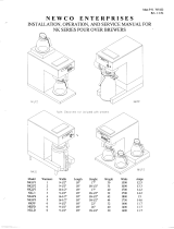
N E W C O E N T E R P R I S E S
INSTALLATION, OPERATION, AND SERVICE MANUAL FOR
NK SERIES AUTOMATIC & FAUCET BREWERS
Weight
Model
Warmers
Width
Length
Height
A / AF
Watts
Amps
NKLP1A-AF
1
9-1/2"
18"
17"
31 / 34
1500
12.5
NKLP2A-AF
2
9-1/2"
18"
18-1/2"
32 / 36
1600
13.3
NKLP3A-AF
3
16-1/2"
18"
17"
39 / 43
1700
14.2
NKL3A-AF
3
9-1/2"
18"
18-1/2"
33 / 36
1700
14.2
NKLP4A-AF
4
9-1/2"
18"
18-1/2"
40 / 44
1800
15
NKLP5A-AF
5
16-1/2"
18"
18-1/2"
45 / 49
1750
14.6
NKLDA-AF
0
9-1/2"
18"
18-1/4"
31 / 35
1400
11.7
NKPPA-AF
0
9-1/2"
18"
22"
32 / 34
1400
11.7
NKPDA-AF
0
11"
18"
26"
34 / 38
1400
11.7
NKT3-3AF
0
13-1/4"
18"
32-1/2"
40 / 44
1400
11.7
NKT5-5AF
0
13-1/4"
18"
36-1/2"
42 / 46
1400
11.7

PLUMBER'S INSTALLATION INSTRUCTIONS
CAUTION: Power to brewer must be OFF before proceeding with plumbing installation.
1) Attach flow/strainer assembly to back of brewer. Strainer inlet will point down.
2) Flush water line before installing brewer. Brewer should be connected to COLD WATER LINE for best operation.
3) Water pressure should be at least 20 lbs. For less than a 25 ft run, use 1/4" copper tubing and connect to 1/2" or larger
water line. For longer runs, use 3/8" copper tubing & connect to 1/2" or larger water line and provide an adapter fitting
for connection to the brewer.
4) If installed with saddle valve, the valve should have a minimum of 1/8" port hole for up to 25 ft run, and 5/16" port hole
for over 25 ft runs.
5) Connect incoming water line to the strainer on the back of the brewer. Manufacturer recommends connecting to copper
tubing.
INSTALLATION INSTRUCTIONS
WARNING: - Read and follow installation instructions before plugging or wiring in machine to electrical circuit. Warranty will
be void if machine is connected to any voltage other than that specified on the name plate.
FILL BREWER TANK WITH WATER BEFORE CONNECTING TO POWER SUPPLY !
ALL MODELS EXCEPT TEA BREWERS
1) Place the decanter under brew basket, raise top evaporation cover and pour three decanters of water through the top pour-
in screen. Water should come through the brew basket as the third decanter of water drains out of the pour in basin. If
brewer does not have a pour in opening remove top cover and pour water directly into receiving pan.
2) Adjust timer to deliver desired amount of water (Timer is located behind front access panel). To brew into a regular 60
oz. decanter little adjustment should be needed. For brewing with the airpot brewer into a 72 oz. airpot the time should be
increased. Turn timer dial clockwise to increase volume of water, and counter clockwise to decrease volume.
3) Brewer is shipped with thermostat turned on, (full clockwise position). Plug or wire in machine to appropriate voltage
circuit as noted on the brewers serial tag. Serial tag is located on rear of brewer.
4) Allow 10 to 15 minutes for water in tank to heat to brewing temperature. (Additional water may drip from brew basket on
initial expansion of water in the tank). This will not occur thereafter.
5) After water has reached brewing temperature (thermostat will click off, heating noise will stop and green ready light will
be on.) turn lower warmer switch (warmer models), or lighted rocker switch (airpot brewers) to the on position. Depress
brew start switch and run a cycle of water to remove expanded water from tank. (Brew cycle may be canceled by turning
the rocker switch back to the OFF position.)
6) Run one cycle to check for the proper temperature setting with an accurate thermometer. Take the temperature of this
water at a point below the brew basket opening, at the start of the brew cycle and when the decanter is half full.
Recommended temperature of the water is approximately 195 F.
7) In higher altitude locations (5000 feet above sea level) the thermostat may have to be adjusted lower to prevent boiling.
8) CAUTION: On faucet models the water faucet will dispense hot water when the handle is depressed. The faucet system is
independent of the brewing system and can be operated during brew cycle. Once brewer is pressurized operate faucet until
water flows smoothly.
TEA BREWERS
1) Remove front access panel from brewer.
2) Place tea urn under brewer and fill tank as described in step 1 above.
3) Plug in brewer. Close needle valve by turning clockwise.

Tea Brewer Installation continued...
4) Set timer to 180 seconds (3 minutes). Start brew cycle by turning lighted rocker switch on and pressing brew start switch.
5) Tea urn should fill with one brew cycle. If not, adjust timer until desired level in tea urn is achieved (3 gallons).
6) Open needle valve by turning counter clockwise 3 to 4 full revolutions. This will give 75 oz of hot water for concentrate
through the sprayhead and the balance of the 3 gallons as cold water through the dilution tube.
7) Replace front access panel.
8) CAUTION: On faucet models the water faucet will dispense hot water when the handle is depressed. The faucet system is
independent of the brewing system and can be operated during brew cycle. Once brewer is pressurized operate faucet until
water flows smoothly.
COFFEE PREPARATION PROCEDURES
1) Place filter into brew basket.
2) Put the proper amount of coffee into the filter.
3) Slide the brew basket into holder.
4) Place empty decanter on warmer located directly under the brew basket and turn corresponding warmer switch to ON
position. NOTE: For airpots, open airpot lid, remove pump stem from airpot, and place airpot under brew basket.
5) Automatic brewers that are plumbed in. Depress brew start switch to begin brew cycle.
Manual brewers that are not plumbed in. Pour decanter of water through pour-in screen into pour in basin.
6) Hot water will be delivered through the sprayhead. This distributes the hot water evenly over the coffee bed within the
brew basket. The coffee brew will drain from the brew basket into the decanter below.
7) The resultant coffee brew should be crystal clear and have the desired properties attainable through excellent extraction.
8) TURN OFF WARMER WHEN NOT IN USE. (All except airpot brewer. Red light indicates warmer is on.)
9) To clean brew basket simply remove from brew rails and dump filter into waste basket. The brewing process, as described
above, can now be started again.
LIMING
To prevent liming problems in tank fittings remove sprayhead and insert deliming spring all the way into the tank. When inserted
into tank properly, no more than ten inches of the spring should be visible at the sprayhead fitting. Saw back and forth five or six
times. This will keep fittings open and clear of lime. In hard water areas this should be done everyday. This process takes
approximately one minute. In all areas the sprayhead should be cleaned at least once a week. Where bad liming has already
occurred, a new complete tank assembly may be installed. The tank may be changed in approximately 5 minutes time.

NK AUTOMATIC & FAUCET BREWERS - PARTS LIST
Index
Part No
Description
Index
Part No
Description
1
100008
Plate, black porcelain
40
704119
Tank only
1
100020
Plate, brown porcelain
41
100176
Connector, male, 1/4F-1/4F
2
100642
Warming element, 220 V 100 W
42
511046
Washer, 7/16" int tooth S/S
2
100187
Warming element, 120 V 100 W
43
100281
Plug, 3/8", plastic
3
100086
Support plate, warming element
44
705203*
Switch plate, NKLP1, -LP2, -PP, -PD, -LD, -T3
4
705371
NK stove top, 1 station cover
44
705201*
Switch plate, NKLP3, -4, -5
4
705370
NK stove top, 2 station cover
45
100058
Nameplate, NEWCO
5
110624
Cover, pour in
46
100145-10
Faucet, Tomlinson with flare
6
110623
Grid, pour in
47
100085
Rocker switch, ON/OFF, lighted
7
705413
NK 1 station cover, welded
48
100343
Start switch, round
7
705419
NK 2 station cover, welded
48
201985
Start switch, rectangular
8
100010
Warming plate assembly, black, 100W 120V
49
705383
Ready light assembly, green
8
100032
Warming plate assembly, brown, 100W 120V
50
101365
Timer only
8
101072
Warming plate assembly, black, 100W 220V
51
201173
Nut, sprayhead
8
101073
Warming plate assembly, brown, 100W 220V
52
100024
Sprayhead, 5 hole
9
705414*
NK 1 station cover ass'y w/ pour in
52
201163
Sprayhead, 6 hole
9
705420*
NK 2 station cover ass'y w/ pour in
53
705379
Tube, 13" discharge, S/S
9
705229
NK plain cover ass'y w/ pour in
54
100253
Label, caution, red
10
100003
Snap bushing, 3/4, plastic
55
705208
Rear panel
11
701200
Slotted hex nut, 3/4-16, brass
56
705197
Cabinet shell ass'y, S/S
12
700015
Washer, 1" OD x 3/4, S/S
57
100022
Power cord, 14/3, 120V 15A
13
700060
Basin, pour in
57
102126
Power cord, 12/3, 120V 20A
14
700016
Gasket, 1.062 OD X .578, silicone
57
100072
Power cord, 10/4, 240V 30A
15
100025
Gasket, sprayhead
58
705210
NK front access panel
16
781555
Gasket, siphon cup
59
705224
Brace, access panel
17
704222
Gasket, delivery tube, 3 hole
60
781031
Rail, L.H.
18
700069
Sprayhead tube
61
781030
Rail, R.H.
19
100175
Grommet, thermostat, silicone
62
700117
Brew basket assembly, brown
20
705595
Copper tube 1/4" OD x 11.38"
62
700118
Brew basket assembly, black
21
102229
Main Thermostat, knob type
63
101035
Strain relief, 120V 15A
22
705381
Tube, 1/4" OD x 4.0" x 10.75", copper
63
100547
Strain relief, 120V 20A
23
100177
Elbow, male 1/4F x 1/8
63
511054
Strain relief, 240V
24
705214
NK automatic tank lid, welded
64
511005
Cord plate, 120V 15A
24
705218
NK faucet tank lid, welded
64
102126
Cord plate, 120V 20A
25
705198
Bracket, main thermostat
64
511007
Cord plate, 240V
26
100043
Thermostat knob
65
100163
Terminal block, 120 V
27
771031
Coil assembly
65
511053
Terminal block, 240 V
28
701170
Main Element, 1400W 120V
66
511023
Nut, 7/16-20, 11/16 hex, brass
28
704155
Main Element, 1700W 120V
67
705228
Snap bushing, 1-1/8", plastic
28
704144
Main Element, 2500W 240V
68
705337
Tube, 1/4" OD x 1.437", S/S
29
705221
NK automatic tank ass'y 1400W 120V
69
511063
Flow control assembly
29
705220
NK faucet tank ass'y, 1400W 120V
70
705338
Tube, 1/4" OD x 1.21" x 1.50", S/S
29
705401
NK automatic tank ass'y, 1700W 120V
71
100161
Tube, 1/4" OD x .88", copper
29
705402
NK faucet tank ass'y 1700W 120V
72
201132
Tee, 1/4" flare
29
705408
NK automatic tank ass'y 2500W 240V
73
100255
Valve, solenoid
29
705410
NK faucet tank ass'y, 2500W 240V
74
100154
Connector, male, 1/4"F x 1/8"
30
705215
NK automatic tank lid ass'y 1400W 120V
75
705596
Tube, solenoid supply, copper
30
705219
NK faucet tank lid, ass'y 1400W 120V
76
705390
Solenoid assembly
30
705398
NK automatic tank lid ass'y 1700W 120V
77
700758
Base top, 1-station
30
705400
NK faucet tank lid ass'y 1700W 120V
77
704115
Base top, 3 station
30
705405
NK automatic lid ass'y 2500W 240V
78
700759*
Base trim plate, S/S
30
705407
NK faucet tank lid ass'y 2500W 240V
79
700760
Base bottom , 1 station, welded
31
100190
Jam nut, 1/2-20, brass
79
704121
Base bottom, 3 station, welded
32
100269
Bracket, hi-limit thermostat
80
100078
Bumper foot w/ screw
33
767110
Valve, needle, angle, 1/4 flare
81
705382*
Base ass'y, 1 station, NKLP1, -2, NKL3
34
110574
Hi-limit thermostat
81
705209*
Base ass'y, 3 station, NKLP3, -4
35
101720
Connector, 3/8C x 1/8P, female
81
705345*
Base ass'y, NKLP5
36
100030
Gasket, .566"ID x .811"OD, brass
81
781010
Base ass'y, NKPP
37
100409
Gasket, .515"ID x .811"OD, brass
81
781245
Base ass'y, NKPD
38
100431
Nut, 9/16-24, brass
81
781115
Base ass'y, NKT3
39
704221
Gasket, tank, silicone
152111
Leg, R.H. NKLD
152112
Leg, L.H. NKLD
*When ordering these parts please specify if replacement parts are for a black or wood grain finish brewer.

WARRANTY
Applies to all equipment manufactured after 2/1/2017. This warranty supersedes
all other previous warranties that are currently in manuals.
Newco warrants equipment manufactured by it for 1 year parts and labor.
Accessories and Dispensers 1 Year parts only.
Electronic Circuit and Control Boards- 3 years parts, 1 year labor.
Equipment manufactured by others and distributed by Newco- please see original equipment manufacturers
warranty, Newco will follow.
These warranty periods run from the date of sale Newco warrants that the equipment manufactured by it will be
commercially free of defects in material and workmanship existing at the time of manufacture and appearing
within the applicable warranty period. This warranty does not apply to any equipment, component or part that
was not manufactured by Newco or that, in Newco’s judgment, has been affected by misuse, neglect, alteration,
improper installation or operation, relocation or reinstallation, improper maintenance or repair, incorrect
voltage applied to the unit at any time, damage or casualty. This warranty does not apply to any equipment
failures related to poor water quality, excessive lime and chlorine and non periodic cleaning and descaling.
Warranty is null and void if muriatic or any other form of hydrochloric acid is used for cleaning or deliming. In
addition, this warranty does not apply to replacement of items subject to normal use including but not limited
to user replaceable parts such as faucet seat cups, sight gauge tubes, washers, o-rings, tubing, seals and
gaskets.
This warranty is conditioned on the Buyer 1) giving Newco prompt notice of any claim to be made under this
warranty by telephone at (800) 556-3926 or by writing to 3650 New Town Blvd, Saint Charles, MO 63301; 2) if
requested by Newco, shipping the defective equipment prepaid to an authorized Newco service location; and 3)
receiving prior authorization from Newco that the defective equipment is under warranty.
THE FOREGOING WARRANTY IS EXCLUSIVE AND IS IN LIEU OF ANY OTHER WARRANTY, WRITTEN OR
ORAL, EXPRESS OR IMPLIED, INCLUDING, BUT NOT LIMITED TO, ANY IMPLIED WARRANTY OF EITHER
MERCHANTABILITY OR FITNESS FOR A PARTICULAR PURPOSE. The agents, dealers or employees of Newco
are not authorized to make modifications to this warranty or to make additional warranties that are binding on
Newco. Accordingly, statements by such individuals, whether oral or written, do not constitute warranties and
should not be relied upon.
If Newco determines in its sole discretion that the equipment does not conform to the warranty, Newco, at its
exclusive option while the equipment is under warranty, shall either 1) provide at no charge replacement parts
and/or labor (during the applicable parts and labor warranty periods specified above) to repair the defective
components, provided that this repair is done by a Newco Authorized Service Representative; or 2) shall
replace the equipment or refund the purchase price for the equipment.
THE BUYER’S REMEDY AGAINST NEWCO FOR THE BREACH OF ANY OBLIGATION ARISING OUT OF THE
SALE OF THIS EQUIPMENT, WHETHER DERIVED FROM WARRANTY OR OTHERWISE, SHALL BE LIMITED, AT
NEWCO’S SOLE OPTION AS SPECIFIED HEREIN, TO REPAIR, REPLACEMENT OR REFUND.
In no event shall Newco be liable for any other damage or loss, including, but not limited to, lost profits, lost
sales, loss of use of equipment, claims of Buyer’s customers, cost of capital, cost of down time, cost of
substitute equipment, facilities or services, or any other special, incidental or consequential damages.

EXPLODED VIEW DRAWING
(NKL3AF SHOWN)

TROUBLE SHOOTING GUIDE
SYMPTOM
POSSIBLE CAUSE
WHAT TO CHECK
REMEDY
CAN'T START BREW CYCLE
1. No water.
2. No power.
3. ON/OFF switch.
4. Brew start switch.
5. Timer or timer harness.
6. Solenoid valve.
1. Incoming water lines & water shut
off valve.
2. Fuse or circuit breaker.
Power cord and plug connections.
3. Switch continuity.
(Normally open.)
4. Switch continuity.
(Normally closed.)
5. Wire leads to solenoid and
black 3-pin connector.
6. (A) Voltage at solenoid valve
terminals. Start a brew cycle and
check for 120 volts AC.
(B) If voltage is present at
terminals, check for water at line
pressure on the inlet side of
solenoid valve.
1. Be sure water shut off is open.
2. Replace or reset circuit protector
3. If ON/OFF switch does not make and
break contact, replace ON/OFF switch.
4. If brew start switch does not make and
break contact, replace brew start switch.
5. Make sure these connections are tight. If
so, and all else checks out OK, replace
timer.
6. (A) If voltage is not present at terminals,
refer to steps 2 through 5.
(B) If voltage is present at terminals and
water at line pressure is present on the
inlet side of the solenoid, but not present
on the outgoing side, replace solenoid.
NO HOT WATER
1. Tank heater.
2. Hi-limit thermostat or main
thermostat.
1. Check the voltage at the tank
heater terminals. Voltage should be
as indicated on the serial tag (on rear
of brewer.)
2. Check the voltage between the
white wire on the tank and the
incoming terminal (blue wire) on
the hi-limit thermostat, then the
outgoing terminal (black wire) on
the hi-limit thermostat.
1. (A) If correct voltage is present at the
tank heater terminals and water in tank is
not being heated, replace the tank heater.
(B) If voltage is not present at the tank
heater terminals refer, to step 2.
(C) If incorrect voltage is present at the
tank heater terminals, check voltage at
outlet.
2. (A) If voltage is present on the incoming
terminal of the hi-limit thermostat, but
not on the outgoing terminal, replace the
hi-limit thermostat.
(B) Check voltage between black and
white wire on the receptacle. If voltage is
not present check outlet or circuit
breaker.
(C) If voltage is not present on the
incoming terminal of the hi-limit
thermostat, replace the main thermostat.
DRIPPING
Faucet models only
1. Not siphoning properly.
2. Solenoid valve not seating
properly.
3. Faucet coil is leaking.
1. Water should flow freely from the
sprayhead.
2. Solenoid valve assembly.
3. Hot water coil.
1. (A) Clean sprayhead holes.
(B) Check tightness of sprayhead tube.
(C) See "LIMING" , Page 2.
2. Be sure spring is in place and any
particles are cleaned from valve seat. If
valve seat is worn or mutilated, replace
solenoid valve.
3. Tighten fittings or replace coil.
STEAMING OR SPITTING
AROUND FUNNEL
1. Main thermostat.
2. High altitude.
1. Thermostat points stuck or out of
calibration.
2. Located above 5,000 feet.
1. (A) Adjust thermostat.
(B) Thermostat should be calibrated or
replaced.
2. See "INSTALLATION
INSTRUCTIONS", Page 2..
FAUCET DRIPPING
1. Clogged valve seat.
1. Valve seat.
1. Disassemble and clean or replace as
required.
WATER KEEPS RUNNING
1. Solenoid valve.
2. Start switch.
3. Timer
1. Refer to "DRIPPING", Step 1.
2. Remove wires from switch and
check continuity.
3. Solid state timers are not
repairable. If timer will not shut
off, replace timer.
1. Refer to "DRIPPING", Step 1.
2. If start switch does not make and break
contact, switch should be replaced.
3. Replace timer.

TROUBLE SHOOTING GUIDE
SYMPTOM
POSSIBLE CAUSE
WHAT TO CHECK
REMEDY
IRREGULAR YIELD
Faucet models only
Faucet models only
1. Not siphoning properly.
2. Timer.
3. Fluctuating water pressure.
4. Solenoid valve.
5. Flow washer.
6. Flow control screen.
7. Faucet coil is leaking.
8. Strainer.
1. Refer to "DRIPPING", Step 1.
2. Timer consistency. Time several
brew cycles.
3. Water pressure.
4. Refer to "DRIPPING", Step 2.
5. Possible lime build up in flow
control.
6. Screen built into flow control.
7. Refer to "DRIPPING", Step 3.
8. Water pressure at output.
1. Refer to "DRIPPING", Step 1.
2. If times are irregular, replace timer.
3. If pressure fluctuates 10-20 PSI during
operation of brew cycle, add a pressure
regulator to inlet side of brewer, set to
lowest pressure level registered. Adjust
timer to yield correct water level.
4. Refer to "DRIPPING", Step 2.
5. Replace flow washer and clean lime
from flow control.
6. Replace or clean screen. Clean lime from
flow control.
7. Refer to "DRIPPING", Step 3.
8. If pressure is low, clean or replace
strainer.
DRY COFFEE REMAINING
IN BREW BASKET AFTER
BREWING
1. Filters.
2. Not siphoning properly.
3. Improper loading of the brew
basket.
1. Are correct filters being used.
2. Refer to "DRIPPING", Step 1.
3. Filter and coffee in brew basket.
1. Insert correct filter.
2. Refer to "DRIPPING", Step 1.
3. Filter should be centered in the brew
basket and coffee bed should be level.
WEAK COFFEE
1. Filters.
2. Not siphoning properly.
3. Improper loading of brew basket.
1. Are correct filters being used.
2. Refer to "DRIPPING", Step 1.
3. Filter and coffee in brew basket.
1. Insert correct filter.
2. Refer to "DRIPPING", Step 1.
3. Filter should be centered in brew basket
and coffee bed should be level.
SOLENOID CHATTER OR
HOWLING
1. Brewer connected to hot water
line.
2. Vibration.
3. High water pressure.
4. Water hammer.
5. 60 cycle vibration.
1. Incoming water line.
2. If brewer is on a metal stand or
counter, neither the bottom pan
nor copper tubing to the brewer
should touch the counter.
3. Water pressure on incoming line.
4. Incoming plumbing.
5. Nut on top of solenoid.
1. Brewer should be connected to cold
water line.
2. Adjust as necessary.
3. If water pressure is over 90 PSI install a
pressure regulator and adjust to 50 PSI.
4. This not the fault of the brewer and can
usually be corrected by rearranging some
plumbing or adding an air chamber to
the incoming water line.
5. Nut should be tight. Tighten as required.
COLD WARMER STATION
(Models with warmers)
1. Warmer - defective.
2. Warmer ON/OFF Switch.
3. Bad harness.
1. Voltage at warmer terminals
should be 120 volts AC.
2. If voltage is not present on warmer
terminals, check continuity of
switch.
3. Check connections between
harness and switch, and between
switch and warmer.
1. If voltage is present on terminals, but
warmer will not heat, replace warmer.
2. If switch does not make and break
continuity when turned off, replace
switch.
3. All connections should be tight.
FAUCET WATER FLOW TOO
FAST OR TOO SLOW
1. No water.
2. Flow too slow or too fast.
1. (A) Incoming water line shut off
valve.
(B) Faucet clogging.
(C) Needle valve.
2. Needle valve.
1. (A) Water shut off valve should be open.
(B) Clean or rebuild faucet.
(C) Needle valve should be open.
2. Increase flow by turning needle valve
counter clockwise, decrease flow by
turning clockwise.

TROUBLE SHOOTING GUIDE CONTINUED
SYMPTOM
POSSIBLE CAUSE
WHAT TO CHECK
REMEDY
CONDENSATION ON
INSIDE OF CABINET
1. Tank lid gasket.
2. Sprayhead tube ass'y.
3. Thermostat grommet.
4. Receiving pan nut.
5. Main thermostat set above 210
degrees.
1. Nicks or cuts in the gasket.
2. Tightness of ass'y to lid.
3. Tight fit. Nicks or cuts.
4. Receiving pan nut loose.
5. Check thermostat calibration.
1. Replace gasket.
2. Tighten sprayhead tube ass'y to tank lid.
3. Adjust or replace grommet.
4. Tighten nut.
5. Calibrate or replace thermostat.
COMPONENT REPLACEMENT INSTRUCTIONS
CAUTION: DISCONNECT BREWER CORD FROM ELECTRICAL OUTLET BEFORE
REMOVAL OF ANY PANEL OR REPLACEMENT OF ANY COMPONENT!
NOTE: IN CANADA REPAIRS ARE TO BE DONE BY CERTIFIED ELECTRICIAN OR BREWER MUST BE RE
INSPECTED TO MAINTAIN APPLICABLE CERTIFICATION
These steps apply to replacement of tank, tank heater, faucet coil, and hi-limit or main thermostat.
1. Remove sprayhead and sprayhead nut by unscrewing in counter clockwise direction.
2. Remove brewer lid. Disconnect electrical connectors from upper warmer plate if applicable.
3. Remove receiving pan by raising the front of the pan while simultaneously pulling forward to clear the inlet tube.
4. Disconnect electrical terminals connected to tank element. Disconnect black lead from main thermostat.
5. Disconnect the inlet to coil and coil to faucet tubes from attached fittings.
6. Lift tank completely out of brewer.
TANK ASSEMBLY, AUTOMATIC AND FAUCET
7. To install new tank ass'y, reverse steps 6 through 1 above.
THERMOSTAT, HI-LIMIT
1. Disconnect wires to hi-limit thermostat.
2. Lift retaining spring slightly to remove old hi-limit thermostat.
3. Check continuity of the new hi-limit thermostat before installing.
4. Slide new hi-limit thermostat into place under the retaining spring. Reconnect wire leads.
5. Ensure that hi-limit thermostat is securely mounted & all electrical connections are tight and isolated.
THERMOSTAT, MAIN
1. Remove two screws which secure thermostat to bracket.
2. Remove grommet from top of tank lid by pressing up with thumb. Pull capillary bulb out through hole.
3. Disconnect thermostat wires.
4. Installation is reverse of removal.
ELEMENT, TANK HEATING
1. Remove the 8 tank lid retaining nuts. Lift tank lid assembly out of tank.
2. Disconnect wire leads from the tank element.
3. Remove the 2 brass nuts, on top side of tank lid, from tank element. Remove element.
4. Install the new tank heating element, washers, and nuts. Tighten securely to insure proper sealing.
5. Inspect tank lid gasket and replace if necessary.
6. Assemble by reversing steps 2 through 1.

WARMER ELEMENT
1. Remove retaining screws from warmer plate.
2. Lift plate and disconnect leads.
3. Remove nuts and washers holding retaining plate and warmer element to plate.
4. Installation is reverse of removal.
HOT WATER COIL
1. Remove the 8 tank lid retaining nuts. Lift tank lid assembly out of tank.
2. Remove the 2 compression nuts from top of hot water coil and remove old coil.
3. Installation is reverse of removal.
FAUCET ASSEMBLY
1. Follow steps 1-3 above for removing receiving pan.
2. Disconnect tank to faucet water line from faucet fitting.
3. Remove brass nut and washer from faucet fitting.
4. Pull out faucet ass'y from front of brewer. Reverse steps for installation of new faucet.
TIMER ASSEMBLY
1. Disconnect timer plug from timer.
2. Remove retaining screws from timer.
3. Remove timer.
4. Installation is reverse of removal.
SOLENOID
1. Disconnect wire leads from solenoid coil.
2. Disconnect brass fitting from inlet side of solenoid assembly.
3. Disconnect brass fitting from outlet side of solenoid assembly.
4. Remove solenoid.
5. Install solenoid insuring arrow points toward left side of brewer.
5. Installation is reverse of removal.
FLOW CONTROL
1. Disconnect lower brass fitting on flow body.
2. Disconnect upper brass fitting on flow body.
3. Remove flow body.
4. Install flow body insuring arrow points towards the top of the brewer.
6. Installation is reverse of removal.
BREW START AND WARMER SWITCHES
1. Remove wire leads from terminals on switch.
2. For rectangular switches: Remove switch by pressing tabs in while pushing switch out towards front of brewer.
3. For round start switch: Remove stainless steel nut on front of brewer and remove switch from inside of brewer.
4. Installation is reverse of removal.
READY LIGHT
1. Disconnect ready light lead from tank element terminal.
2. Disconnect ready light lead from terminal block.
3. Remove ready light by pressing tabs in while pushing light out towards front of brewer.
4. Installation is reverse of removal.

WIRING DIAGRAMS
NK Automatic/Automatic With Faucet - 120 or 120/240 V; 208 V
NK Automatic/Automatic With Faucet - 240 or 208 V
Newco Enterprises, Inc. * 1735 South River Rd. * P.O. Box 852 * St. Charles, MO 63302
/