Page is loading ...

Installing S50N and
S50V Systems

Notes, Cautions, and Warnings
NOTE: A NOTE indicates important information that helps you make better use of your computer.
CAUTION: A CAUTION indicates potential damage to hardware or loss of data if instructions are not
followed.
WARNING: A WARNING indicates a potential for property damage, personal injury, or death.
Information in this publication is subject to change without notice.
© 2010 Dell Force10. All rights reserved.
Reproduction of these materials in any manner whatsoever without the written permission of Dell Inc. is strictly forbidden.
Trademarks used in this text: Dell™, the DELL logo, Dell Precision™, OptiPlex™, Latitude™, PowerEdge™, PowerVault™,
PowerConnect™, OpenManage™, EqualLogic™, KACE™, FlexAddress™ and Vostro™ are trademarks of Dell Inc. Intel
®
, Pentium
®
,
Xeon
®
, Core™ and Celeron
®
are registered trademarks of Intel Corporation in the U.S. and other countries. AMD
®
is a registered trademark
and AMD Opteron™, AMD Phenom™, and AMD Sempron™ are trademarks of Advanced Micro Devices, Inc. Microsoft
®
, Windows
®
,
Windows Server
®
, MS-DOS
®
and Windows Vista
®
are either trademarks or registered trademarks of Microsoft Corporation in the United
States and/or other countries. Red Hat Enterprise Linux
®
and Enterprise Linux
®
are registered trademarks of Red Hat, Inc. in the United States
and/or other countries. Novell
®
is a registered trademark and SUSE ™ is a trademark of Novell Inc. in the United States and other countries.
Oracle
®
is a registered trademark of Oracle Corporation and/or its affiliates. Citrix
®
, Xen
®
, XenServer
®
and XenMotion
®
are either registered
trademarks or trademarks of Citrix Systems, Inc. in the United States and/or other countries. VMware
®
, Virtual SMP
®
, vMotion
®
, vCenter
®
,
and vSphere
®
are registered trademarks or trademarks of VMWare, Inc. in the United States or other countries.
Other trademarks and trade names may be used in this publication to refer to either the entities claiming the marks and names or their products.
Dell Inc. disclaims any proprietary interest in trademarks and trade names other than its own.
November 2011 P/N 101-00059-03

Contents | 3
Contents
1 About this Guide
Information Symbols and Warnings . . . . . . . . . . . . . . . . . . . . . . . . . . . . . . . . . . . . . . 5
Related Publications . . . . . . . . . . . . . . . . . . . . . . . . . . . . . . . . . . . . . . . . . . . . . . . . . . 7
2 System Overview
Equipment. . . . . . . . . . . . . . . . . . . . . . . . . . . . . . . . . . . . . . . . . . . . . . . . . . . . . . . . . 10
Features . . . . . . . . . . . . . . . . . . . . . . . . . . . . . . . . . . . . . . . . . . . . . . . . . . . . . . . . . . 10
Ports . . . . . . . . . . . . . . . . . . . . . . . . . . . . . . . . . . . . . . . . . . . . . . . . . . . . . . . . . . . . . 10
System Status . . . . . . . . . . . . . . . . . . . . . . . . . . . . . . . . . . . . . . . . . . . . . . . . . . . . . 11
LED Displays . . . . . . . . . . . . . . . . . . . . . . . . . . . . . . . . . . . . . . . . . . . . . . . . . . 11
3 Site Preparations
Site Selection . . . . . . . . . . . . . . . . . . . . . . . . . . . . . . . . . . . . . . . . . . . . . . . . . . . . . . 13
Cabinet Placement . . . . . . . . . . . . . . . . . . . . . . . . . . . . . . . . . . . . . . . . . . . . . . . . . . 13
Rack Mounting . . . . . . . . . . . . . . . . . . . . . . . . . . . . . . . . . . . . . . . . . . . . . . . . . . . . . 14
Fans and Airflow . . . . . . . . . . . . . . . . . . . . . . . . . . . . . . . . . . . . . . . . . . . . . . . . . . . . 14
Power . . . . . . . . . . . . . . . . . . . . . . . . . . . . . . . . . . . . . . . . . . . . . . . . . . . . . . . . . . . . 14
S50N-DC . . . . . . . . . . . . . . . . . . . . . . . . . . . . . . . . . . . . . . . . . . . . . . . . . . . . . . 14
S50N and S50V. . . . . . . . . . . . . . . . . . . . . . . . . . . . . . . . . . . . . . . . . . . . . . . . . 15
Power over Ethernet (PoE) Support . . . . . . . . . . . . . . . . . . . . . . . . . . . . . . . . . 15
Storing Components . . . . . . . . . . . . . . . . . . . . . . . . . . . . . . . . . . . . . . . . . . . . . . . . 16
Tools Required . . . . . . . . . . . . . . . . . . . . . . . . . . . . . . . . . . . . . . . . . . . . . . . . . . . . . 16
4 Installing the Switch
Inserting Optional Modules (10-Gigabit or Stacking) . . . . . . . . . . . . . . . . . . . . . . . . 17
Installing the System on a Tabletop . . . . . . . . . . . . . . . . . . . . . . . . . . . . . . . . . . . . . 18
Installing the System in a Rack or Cabinet . . . . . . . . . . . . . . . . . . . . . . . . . . . . . . . 19
Two-Post Rack Mounting. . . . . . . . . . . . . . . . . . . . . . . . . . . . . . . . . . . . . . . . . . 19
Four-Post Rack-mounting with Threaded Rails. . . . . . . . . . . . . . . . . . . . . . . . . 19
Four-Post Rack-mounting with Cage Nuts. . . . . . . . . . . . . . . . . . . . . . . . . . . . . 21
Stacking . . . . . . . . . . . . . . . . . . . . . . . . . . . . . . . . . . . . . . . . . . . . . . . . . . . . . . . . . . 23
Using SFTOS Stacking Commands. . . . . . . . . . . . . . . . . . . . . . . . . . . . . . . . . . 24
Using FTOS Stacking Commands. . . . . . . . . . . . . . . . . . . . . . . . . . . . . . . . . . . 24
Connecting Stack Ports (optional) . . . . . . . . . . . . . . . . . . . . . . . . . . . . . . . . . . . 25
Supplying Power. . . . . . . . . . . . . . . . . . . . . . . . . . . . . . . . . . . . . . . . . . . . . . . . . . . . 27
S50N-DC . . . . . . . . . . . . . . . . . . . . . . . . . . . . . . . . . . . . . . . . . . . . . . . . . . . . . . 27
5 Installing Backup Power
Backup Power Components . . . . . . . . . . . . . . . . . . . . . . . . . . . . . . . . . . . . . . . . . . . 29

4 | Contents
www.dell.com | support.dell.com
The Power Connections on the Switch. . . . . . . . . . . . . . . . . . . . . . . . . . . . . . . . . . . 30
Installing the Backup DC Power Supply for the S50V. . . . . . . . . . . . . . . . . . . . . . . . 30
Inserting Tandem S50V PSUs into a Rack . . . . . . . . . . . . . . . . . . . . . . . . . . . . 31
Connecting the S50V DC-to-DC Cable . . . . . . . . . . . . . . . . . . . . . . . . . . . . . . . 32
Installing the Backup DC Power Supply for the S50N . . . . . . . . . . . . . . . . . . . . . . . 34
DC Components . . . . . . . . . . . . . . . . . . . . . . . . . . . . . . . . . . . . . . . . . . . . . . . . . . . . 34
Installing the External Power Shelf (optional) . . . . . . . . . . . . . . . . . . . . . . . . . . . . . . 35
Inserting an S50N PSU into the EPS . . . . . . . . . . . . . . . . . . . . . . . . . . . . . . . . . . . . 36
Connecting the DC-to-DC Cable for the S50N PSU . . . . . . . . . . . . . . . . . . . . . 37
6 Installing Ports
Accessing the Console Port . . . . . . . . . . . . . . . . . . . . . . . . . . . . . . . . . . . . . . . . . . . 41
Connecting S50V Ethernet Ports with PoE. . . . . . . . . . . . . . . . . . . . . . . . . . . . . . . . 42
Installing Optics. . . . . . . . . . . . . . . . . . . . . . . . . . . . . . . . . . . . . . . . . . . . . . . . . . . . . 43
Installing SFPs . . . . . . . . . . . . . . . . . . . . . . . . . . . . . . . . . . . . . . . . . . . . . . . . . . . . . 43
Installing XFPs . . . . . . . . . . . . . . . . . . . . . . . . . . . . . . . . . . . . . . . . . . . . . . . . . . . . . 44
7 Switch Specifications
Chassis Physical Design. . . . . . . . . . . . . . . . . . . . . . . . . . . . . . . . . . . . . . . . . . . . . . 47
Environmental Parameters . . . . . . . . . . . . . . . . . . . . . . . . . . . . . . . . . . . . . . . . . . . . 48
Power Requirements. . . . . . . . . . . . . . . . . . . . . . . . . . . . . . . . . . . . . . . . . . . . . . . . . 48
AC Power Requirements . . . . . . . . . . . . . . . . . . . . . . . . . . . . . . . . . . . . . . . . . . 48
DC Power Requirements. . . . . . . . . . . . . . . . . . . . . . . . . . . . . . . . . . . . . . . . . . 48
Agency Compliance . . . . . . . . . . . . . . . . . . . . . . . . . . . . . . . . . . . . . . . . . . . . . . . . . 49
Safety Standards and Compliance Agency Certifications . . . . . . . . . . . . . . . . . 51
Electromagnetic Compatibility (EMC) . . . . . . . . . . . . . . . . . . . . . . . . . . . . . . . . 51
Product Recycling and Disposal . . . . . . . . . . . . . . . . . . . . . . . . . . . . . . . . . . . . 52
8 Technical Support
The iSupport Website . . . . . . . . . . . . . . . . . . . . . . . . . . . . . . . . . . . . . . . . . . . . . . . . 55
Accessing iSupport Services . . . . . . . . . . . . . . . . . . . . . . . . . . . . . . . . . . . . . . . 55
Contacting the Technical Assistance Center . . . . . . . . . . . . . . . . . . . . . . . . . . . . . . 56
Locating Serial Numbers. . . . . . . . . . . . . . . . . . . . . . . . . . . . . . . . . . . . . . . . . . . . . . 56
Requesting a Hardware Replacement . . . . . . . . . . . . . . . . . . . . . . . . . . . . . . . . . . . 57
Index

About this Guide | 5
1
About this Guide
This guide provides site preparation recommendations, step-by-step procedures for rack mounting and
desk mounting the S50V or S50N switches (and related models, such as S50N-DC), inserting optional
modules, and connecting to a power source. Except where noted, descriptions and instructions in this
guide apply to all variants of these switches.
After you have completed the hardware installation and power-up of the switch, refer to the SFTOS™
Configuration Guide for software configuration information and to the SFTOS™ Command Reference
for detailed Command Line Interface (CLI) information.
Information Symbols and Warnings
The following graphic symbols are used in this document to bring attention to hazards that exist when
handling the switch and its components. Please read these alerts and heed their warnings and cautions.
Table 1-1
describes symbols contained in this guide.
WARNING: The installation of this equipment shall be performed by trained and qualified personnel only.
Read this guide before installing and powering up this equipment. This equipment contains two power cords.
Disconnect both power cords before servicing.
WARNING: Class 1 laser product.
Attention: Produit laser de classe 1
Warnung: Laserprodukt der Klasse
1
Table 1-1. Information Symbols
Symbol Warning Description
Note This symbol informs you of important operational information.
Caution This symbol informs you that improper handling and installation could result in equipment
damage or loss of data.
Warning This symbol signals information about hardware handling that could result in injury.

6 | About this Guide
www.dell.com | support.dell.com
WARNING: This equipment contains optical transceivers, which comply with the limits of Class 1 laser
radiation. Visible and invisible laser radiation may be emitted from the aperture of the optical transceiver ports
when no cable is connected. Avoid exposure to laser radiation and do not stare into open apertures.
WARNING: Building Supply Notice for AC Power Supply Use. This product relies on the building's installation
for short-circuit (overcurrent) protection. Ensure that a fuse or circuit breaker no larger than 120 VAC, 15A
U.S. (240 VAC, 10A international) is used on the phase conductors (all current-carrying conductors).
Attention: Pour ce qui est de la protection contre les courts-circuits (surtension), ce produit dépend de
l'installation électrique du local. Vérifier qu'un fusible ou qu'un disjoncteur de 120 V alt., 15 A U.S. maximum
(240 V alt., 10 A international) est utilisé sur les conducteurs de phase (conducteurs de charge).
Warnung: Dieses Produkt ist darauf angewiesen, daß im Gebäude ein Kurzschluß- bzw.
Überstromschutz installiert ist. Stellen Sie sicher, daß eine Sicherung oder ein Unterbrecher von nicht mehr
als 240 V Wechselstrom, 10 A (bzw. in den USA 120 V Wechselstrom, 15 A) an den Phasenleitern (allen
stromführenden Leitern) verwendet wird.
WARNING: Building Supply Notice for DC Power Supply Use. An external disconnect must be provided and
be easily accessible. Dell Force10 recommends the use of a 60A circuit breaker.
ATTENTION: Un interrupteur externe doit être fournis et doit être facilement accessible. Dell Force10
recommande l'utilisation d'un disjoncteur de 60Ampères.
WARNUNG: Eine leicht zugängliche Tren Dell Force10 nvorrichtung muss in der Verdrahtung eingebaut sein.
Dell Force10 empfiehlt einen 60A Sicherungsautomaten zu benutzen
CAUTION: Wear grounding wrist straps when handling this equipment to avoid ESD damage.
CAUTION: Earthing (AKA grounding) connection essential before connecting supply. Always make the
ground connection first and disconnect it last.
CAUTION: Disposal of this equipment should be handled according to all national laws and regulations. See
Product Recycling and Disposal on page 52
.
CAUTION: This unit has more than one power supply connection; all connections must be removed to
remove all power from the unit.
ATTENTION: Cette unité est équipée de plusieurs raccordements d'alimentation. Pour supprimer tout courant
électrique de l'unité, tous les cordons d'alimentation doivent être débranchés.
WARNUNG: Diese Einheit verfügt über mehr als einen Stromanschluß; um Strom gänzlich von der Einheit
fernzuhalten, müssen alle Stromzufuhren abgetrennt sein.
CAUTION: Lithium Battery Notice. Danger of explosion if battery is replaced with incorrect type. Replace only
with the same type recommended by the manufacturer. Dispose of used batteries according to the
manufacturer's instructions.
ACHTUNG - Explosionsgefahr wenn die Battery in umgekehrter Polarität eingesetzt wird. Nur miteinem
gleichen oder ähnlichen, vom Hersteller empfohlenen Typ, ersetzen. Verbrauchte Batterien müssen per den
Instructionen des Herstellers verwertet werden.
ATTENTION - Il y a danger d'explosion s'il a remplacement incorrect de la batterie. Remplacer uniquement
avec une batterie du meme type ou d'un type equivalent recommande par le constructeur. Mettre au rebut les
batteries usagees conformement aux instructions du fabricant.
NOTE: Other cautionary statements appear in context elsewhere in this book.

About this Guide | 7
Related Publications
The S50V or S50N (and related models, such as S50N-DC) can run on either FTOS or SFTOS.
Depending on which software your system contains, refer to the following documents:
The Technical Documentation CD-ROM contains the S-Series hardware guides and the FTOS and
SFTOS files listed above, respectively, except for the Release Notes. The CD-ROMs also have:
• MIBs: Files for all SNMP MIBs supported by the software
• Data sheets: Links to Dell Force10 product data sheets
NOTE: Documentation CD-ROMs do not have software. For the most recent documentation and software,
please visit iSupport (registration for access to some sections is required): http://www.force10networks.com/
CSPortal20/Main/SupportMain.aspx
NOTE: The iSupport website also has a section for S-Series techtips and FAQs.
Table 1-2. Documentation
FTOS Documentation SFTOS Documentation
FTOS Configuration Guide for the S-Series SFTOS Configuration Guide
FTOS Command Reference for the S-Series SFTOS Command Reference
S-Series and FTOS Release Notes S-Series and SFTOS Release Notes
S25P Quick Reference

8 | About this Guide
www.dell.com | support.dell.com

System Overview | 9
2
System Overview
The S50V and S50N models of the Dell Force10 S-Series are stackable, Layer 2 switch/Layer 3 routers
with 48 built-in 10/100/1000 Base-T ports, four SFP ports, and up to four optional 10-Gigabit (10GbE)
ports (XFP or CX4), in two expansion slots.
Figure 2-1
shows the front panel of the S50V. The S50N has
the same layout; just the catalog number differs. The S50N-DC (see
Figure 3-1 on page 15
) differs only in
that DC1 and DC2 status LEDs appear where the AC and DC status LEDs are on the S50V and S50N.
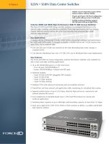
Figure 2-1. The S50V Front View
Figure 2-2. The S50V Rear View
The rear of the S50N differs only in that its DC terminal block has a different lug arrangement, as shown
in
Figure 3-1 on page 15
, while the S50N-DC replaces the AC receptacle with a second DC terminal
block.
fn00157s50V
OK
AC
XFP49
XFP51
Ethernet Ports (10/100/1000)
LEDs
Alarm
DC
XFP51
XFP52
SFP
Ports (45-48)
Status Panel
Shared
10/100/1000
Ports (45-48)
Stack ID
Indicator
LED
P52
51
XFP50
AC
XFP49
DC
Alarm
Stack ID
RJ-45 Console Port
Catalog # (S50-01-GE-48T-V)
S50-01-GE-48T-V
Link/Active
Indicator LEDs
(SFP Ports 45-48)
fn00158s50V
10-Gigabit Modules or Stacking Modules (optional).
Optical ports numbered from left to right.
DC Power
Ground Connector
AC Power Receptacle
11.5
FG
-48V
RTN
-48V
Current
Sharing
Label (Part #, Serial #, MAC Address, Bar Code, FRU #)
Ethernet Port Numbers
49 to 52, Right to Left

10 | System Overview
www.dell.com | support.dell.com
Equipment
The following items are necessary to install the system:
• The switch
• At least one grounded AC or DC power source per S50V or S50N switch; one or two grounded DC
power sources per S50N-DC switch.
• Cable (included) to connect the AC power source to the switch
• Brackets for rack installation (included)
• Screws for rack installation (included) and #2 Phillips screwdriver (not supplied)
Other optional components are:
• Stacking cables for connecting switches when stacked (not supplied). See Connecting Stack Ports
(optional) on page 25.
• Backup DC Power Module (see Chapter
, Installing Backup Power, on page 29)
• Optical networking components (see Chapter
, Installing Ports, on page 41)
• Stacking components (see Ports
, below)
Features
• Internal power supply with power redundancy from built-in 1+1 AC/DC (AC: 110v/220v auto-detect;
DC: -48V standards-based with terminal-type connectors). The one difference between the S50V and
S50N is that the S50V has built-in support for 360W Power over Ethernet (PoE) — IEEE 802.3af —
with power allocation control available through the CLI.
• 256MB RAM and 32MB internal Flash memory
• Supports up to 32000 MAC address entries, with hardware-assisted aging
• Stackable switch features
• 19-inch rack-mountable and standard 1U chassis height
• Six built-in fans with automatic speed adjustment for temperature changes
• Supports 9252-byte jumbo frames in FTOS, 9216-byte jumbo frames in SFTOS
• Back-pressure support at half-duplex, IEEE 802.3x flow control at full duplex
• Extensive LED system with per-port LEDs
Ports
• 48 fixed 10/100/1000 Mbps auto-sensing and auto-MDIX RJ45 ports, up to 15.4W PoE each
• Four ports capable of using 10/100/1000 Base-T or 1000 Base-X using auto-media detect
• Console port (see Chapter
, Installing Ports, on page 41): Supplied with console cable (straight-through
Ethernet copper cable) and terminal adapter (DB-9 to RJ-45)

System Overview | 11
• Expansion slots that accept any combination of the following optional, high-capacity uplink modules:
10GbE XFP (two ports), 10GbE CX4 (two ports), 12G stacking (two ports) or 24G stacking (one port).
See Inserting Optional Modules (10-Gigabit or Stacking) on page
17 and Connecting Stack Ports
(optional) on page 25.
System Status
Chassis status information can be derived in several ways, including physical LED displays and boot
menu options, both discussed here, along with CLI
show commands, and SNMP traps. For details on
those options, see the Command Reference and Configuration Guide for your software (FTOS or
SFTOS).
LED Displays
As shown in
Figure 2-2 on page 9
, the front panel of the switch contains several sets of LEDs:
• Stack ID: This is the LED at the far left of the front panel labeled “STACK ID”. See Stack ID in
T
able 2-2 on page 12). For more on stack unit numbering, see Stacking on page 23.
• Status indicator LEDs on the left side of the front panel, to the right of the Stacking LED. See T
able 2-2.
• Each port has status indicator LEDs, described in T
able 2-1.
* The LEDs for a 10/100/1000 port numbered 45 through 48 are inactive if the shared SFP port (also labeled 45 through 48) is
enabled
.
Table 2-1. Port LED Displays
Feature Description
10/100/1000 Port LED* Speed LED (left side of each port)
Green — 1000M
Amber — 100M
Off — 10M
Link/Active LED (right side of each port)
Green — Link up on this port
Blinking Green — Activity, transmitting or receiving packet at this port.
Amber — Link up and power supplied on this port
Off — No Link detected at this port
SFP Port LED* Link/Activity LED
Green — Link up on this port
Blinking Green — Activity, transmitting or receiving packet in link up state
Off — No Link detected at this port
XFP Port LED Link/Activity LED (Each XFP port has a status LED on the module and in the Status
Display at the left front of the switch)
Green — Link up on this port
Blinking Green — Activity, transmitting or receiving packet in link up state
Off — No Link detected at this port

12 | System Overview
www.dell.com | support.dell.com
NOTE: As suggested by the footnote above, the fiber SFP ports have priority over the four 10/100/1000 ports
with the same number.
The following table describes the LED status indicators on the left side of the front panel.
*The four XFP LEDs on the front panel also indicate the status when CX4 ports are installed in the bay.
Table 2-2. Status Panel LED Display
Label LED Color Description
Left Side of the Status Panel
OK Green
Off
Green Blinking
Amber
Unit is online.
Unit is powered off.
Unit is booting up. (blinking rate is 16 Hz)
Error during boot-up.
AC (on the S50V
and S50N)
DC1 (on the
S50N-DC)
Green
Amber
Off
Power supply is present and OK.
Power supply is present but failed.
Power supply is not present.
XFP49* Green
Blinking Green
Off
A valid 10G link is established on the port.
Transmitting or receiving packets on the port.
No link is established on the port.
XFP50* Green
Blinking Green
Off
A valid 10G link is established on the port.
Transmitting or receiving packets on the port.
No link is established on the port.
STACK ID Green Indicates the stack ID (sometimes called "switch ID") of the unit.
Starting with FTOS 7.8.1.0:
•“A” is displayed to the left of the stack ID if the unit is a standalone or
master (management) unit.
•“B” is displayed for a standby unit. (Actually, it’s an 8, because of the
limitations of the 7-segment LED.)
•“0” is displayed next to the stack ID, as before, for the other units.
Right Side of the Status Panel
Alarm Amber
Red
Off
Minor alarm: Fan or temperature is operating outside parameters.
Major alarm
No alarm
DC (on the S50V
and S50N)
DC2 (on the
S50N-DC)
Green
Amber
Off
Power supply is present and OK.
Power supply is present but failed.
Power supply is not present.
XFP51* Green
Blinking Green
Off
A valid 10G link is established on the port.
Transmitting or receiving packets on the port.
No link is established on the port.
XFP52* Green
Blinking Green
Off
A valid 10G link is established on the port.
Transmitting or receiving packets on the port.
No link is established on the port.

Site Preparations | 13
3
Site Preparations
This chapter describes requirements and procedures to install your system in the following topics:
• Site Selection
• Cabinet Placement on page 13
• Rack Mounting on page 14
• Fans and Airflow on page 14
• Power on page 14
• Storing Components on page 16
• Tools Required on page 16
For detailed switch specifications, refer to
Chapter , Switch Specifications, on page 47
.
NOTE: Install the switch into a rack or cabinet before installing any optional components.
Site Selection
Make sure that the area where you install your switch meets the following safety requirements:
• Near an adequate power source. Connect the system to the appropriate branch circuit protection as
defined by your local electrical codes. See cautions in Information Symbols and
Warnings on page 5.
• Environmental temperature between 32° – 122°F (0° – 50°C).
• Relative humidity that does not exceed 85% non-condensing.
• In a dry, clean, well-ventilated and temperature-controlled room, away from heat sources such as hot air
vents or direct sunlight.
• Away from sources of severe electromagnetic noise.
• Positioned in a rack, cabinet, or on a desktop with adequate space in the front, rear, and sides of the unit
for proper ventilation, and access.
Cabinet Placement
The cabinet must meet the following criteria:
• Minimum cabinet size and airflow are according to the EIA standard.
• Minimum of 5 inches (12.7 cm) between the side intake and exhaust vents and the cabinet wall.

14 | Site Preparations
www.dell.com | support.dell.com
Rack Mounting
When you prepare your equipment rack, ensure that the rack is earth ground. The equipment rack must be
grounded to the same ground point used by the power service in your area. The ground path must be
permanent.
Fans and Airflow
Ventilation is side-to-side, with six fans on the left side of the switch. For proper ventilation, position the
switch in an equipment rack (or cabinet) with a minimum of five inches (12.7 cm) of clearance around the
side intake and exhaust vents. When two S-Series systems are installed side by side, position the two
chassis at least 5 inches (12.7 cm) apart to permit proper airflow. The acceptable ambient temperature
ranges are listed in
Environmental Parameters on page 48
.
As listed in
Table 2-2 on page 12
, the front panels of the S50N and S50V series have an Alarm status
LED, which is green when the switch is operating within required temperature parameters and all
components are operating normally, including fans. The LED is amber when the temperature or
components are outside expected parameters, red in a major alarm.
The fan speed increases when the temperature reaches 72 degrees C, and decreases to normal speed when
the temperature falls to 57 degrees C. The switch never intentionally stops managing traffic.
SFTOS logs a temperature warning message when a temperature of 77 degrees C is reached, and logs
another message when the temperature returns to normal. The Command Line Interface (CLI) also
reports an alarm.
Use the
show logging command to see the log messages. For details, see the System Logs chapters of the
SFTOS Command Reference and SFTOS Configuration Guide.
In a stack, each unit has its own temperature monitoring and control. Status logging is identified by unit
in the system log.
Fan replacement in the field is not offered as an option.
Power
S50N-DC
As shown below, the right side of the S50N-DC contains two terminal blocks for two 150W DC power
supply inputs. The terminal blocks are labeled DC1 and DC2, which corresponds to the labels of the
status LEDs on the front left of the switch. When both blocks are connected, they act in load-sharing
mode with backup capability (one power supply can run the whole system).

Site Preparations | 15
Figure 3-1. The S50N-DC Rear View
S50N and S50V
CAUTION: The power supply cord is used as the main disconnect device; ensure that the socket-outlet is
located/installed near the equipment and is easily accessible.
As shown in
Figure 2-2 on page 9
, the rear of the S50N and S50V models have both an auto-sensing 110/
220V AC receptacle and a standard -48V terminal-type DC connector. The rear of an S50N differs only
in the arrangement of the lugs on its DC terminal block
(Figure 3-1)
. Each system ships only with the AC
power cord. There is no power switch. Connecting the switch to either an AC or DC power source starts
the switch.
On both the S50N and S50V, either the AC or DC power supplies alone are sufficient to power the switch.
When both AC and DC power supplies are connected, they act in roughly a 60%/40% load-sharing mode.
On the S50V, when the Dell Force10 470W DC Backup Power Supply is connected to the Current
Sharing connection on the S50V DC terminal block, the switch uses the DC and AC power supplies in
current-sharing (load-sharing plus additive) mode, so that the total capability is 470W+470W = 940W.
See
Backup Power Components on page 29
.
Dell Force10 also offers an external 180W DC power supply for the S50N and S50N-DC models, the
same power supply used by the S50. However, the connections differ from those on the S50, so the power
supply ships with DC cables to support each model. Rack-mounting hardware is supplied. For details on
connecting to a power source, see
Supplying Power on page 27
.
Power over Ethernet (PoE) Support
Along with the optional DC power supply noted above, the S50V includes an internal 470W power
supply that supports both the operation of the switch and an independent power distribution system to
supply power to the 48 copper Ethernet ports, supporting the IEEE 802.3af standard for Power over
Ethernet (PoE). Connect only powered devices that adhere to IEEE 802.3af.
fn00158s50N-DC
10-Gigabit Modules or Stacking Modules (optional).
Optical ports numbered from left to right.
DC2
Ground Connector
DC1
FG
-48V
RTN
-48V
Label (Part #, Serial #, MAC Address, Bar Code, FRU #)
Ethernet Port Numbers
49 to 52, Right to Left
FG
-48V
RTN
-48V

16 | Site Preparations
www.dell.com | support.dell.com
The total PoE power budget for the switch is between 320W and 790W, depending on the power sources
available. If the external 470W Redundant Power Supply (catalog # S50-01-PSU-V) from Dell Force10
is attached to the Current Sharing terminal (see
Chapter , Installing Backup Power, on page 29
), you can
use the
power-budget command in FTOS to convert the power supply to current-sharing mode to
provide up to 790W of PoE. When running SFTOS, use the
inlinepower threshold command.
Each port can provide a maximum of 15.4W, subject to the power budget, voltage, power priority, and
power limit settings. PoE is, by default, enabled globally on a first-come, first-serve basis, until it exceeds
the total available power. Alternatively, the switch administrator can use the CLI to allocate power on a
per-port and a per-stack-unit basis, with per-port power limits and port prioritization. For a brief
introduction in this guide to the PoE commands, see
Connecting S50V Ethernet Ports with PoE on page 42
.
For details, see the PoE Commands sections in the Command Reference and Configuration Guide for
your software.
Storing Components
If you do not install your system and components immediately, Dell Force10 recommends that you
properly store the switch and all optional components until you are ready to install them.
WARNING: Electrostatic discharge (ESD) damage can occur when components are mishandled. Always
wear an ESD-preventive wrist or heel ground strap when handling the switch and its accessories. After you
remove the original packaging, place the switch and its components on an antistatic surface.
Follow these storage guidelines:
• Storage temperature should remain constant, in the range from -40° to 158° F (-40°C to 70° C).
• Storage humidity should be within 10 to 90% (relative humidity), non-condensing
• Store on a dry surface or floor, away from direct sunlight, heat, and air conditioning ducts.
• Store in a dust-free environment.
Tools Required
S-Series switches are shipped fully assembled, encased in foam. A utility knife is useful for cutting the
packing tape, and a Phillips #2 screwdriver is required for attaching rack screws, and is also used for
making some attachments, including DC cables and rear cover plates. Wear an anti-static guard, as noted
above.

Installing the Switch | 17
4
Installing the Switch
To install S50V or S50N systems, Dell Force10 recommends that you complete the installation
procedures in the order presented in this chapter:
• Inserting Optional Modules (10-Gigabit or Stacking)
• Installing the System on a Tabletop on page 18
• Installing the System in a Rack or Cabinet on page
19
• Stacking on page
23
• Supplying Power on page 27
WARNING: As with all electrical devices of this type, take all the necessary safety precautions to prevent injury when
installing this system. Electrostatic discharge (ESD) damage can occur if components are mishandled. Always wear an
ESD-preventive wrist or heel ground strap when handling the switch and its components. See other relevant cautions in
the Preface.
Inserting Optional Modules (10-Gigabit or Stacking)
The S50V (catalog number S50-01-GE-48T-V) and S50N (catalog number S50-01-GE-48T-AC for AC-
powered version of S50N; S50-01-GE-48T-DC for S50N-DC) have two expansion slots in the back of
the chassis, for which there are four modules available:
The system supports any of the modules inserted in any combination of slots (although connecting all
four ports of two 12G stacking modules is not supported, nor is connecting a 12G stack port in one switch
to a 24G stack port in another switch). The ports are numbered 49 through 52, from left to right as you
face the front of the chassis. So, for clarity in the use of the CLI in port assignment, if you are only using
one XFP or CX4 module, insert it in the left-most expansion slot.
NOTE: The 10G modules cannot be used for stacking. See
Connecting Stack Ports (optional) on
page 25
.
Module Description Catalog Number
2-port 10GbE XFP (optical connection) S50-01-10GE-2P
2-port 10GbE CX4 (copper connection) S50-01-10GE-2C
2-port 12GbE Stacking S50-01-12G-2S
1-port 24GbE Stacking S50-01-24G-1S

18 | Installing the Switch
www.dell.com | support.dell.com
To install a module, follow the steps below:
Installing the System on a Tabletop
The system can be positioned on a stable tabletop. Four rubber standoffs are provided for that purpose in
the plastic bag in the switch shipping box. Keep the following in mind when using a tabletop:
Step Task
1 If the system is on, save the running configuration, if desired (and different from the startup configuration) with
the command write memory. Then power down the system by unplugging it from its power source.
CAUTION: Hot-swapping (inserting or removing) a module can crash and lock up the system, requiring a
power cycle.
2 Use a #2 Phillips screwdriver to remove either a module faceplate or an existing module. Note that these slots,
when used for 10G Ethernet ports, are assigned port numbers from left to right as you face the front of the system.
So, for clarity in programming those ports, you might favor the left-most slot for the first 10G module that you
install.
3 Grasp the module faceplate, and remove the module from its packaging, then slide it into the slot until the module
faceplate is flush with the rear cover of the system.
4 Secure the captive screws on either side of the module.
5 The optical XFP 10-Gigabit module (Catalog # S50-01-10GE-2P) requires additional XFP transceiver inserts,
which are not included in the module kit. See
Installing XFPs on page 44
or the installation instructions that come
with the transceiver.
CAUTION: You can connect a CX4 cable to an XFP port through a CX4 XFP converter (catalog number
GP- XFP-1CX4) in the slot. However, an XFP port does not support the use of the cx4-cable-length command,
discussed next.
CX4 module (catalog number S50-01-10GE-2C) ports do not require inserts. If you are installing a CX4 module,
and you are connecting the ports with a cable substantially shorter or longer than 5 meters, use the cx4-cable-
length command to set the signal strength. Use cx4-cable-length long for a longer cable, cx4-cable-length short
for a shorter cable. For details when using FTOS, see the Interfaces chapter in the FTOS Command Reference.
When using SFTOS, see the System Management Commands chapter in the SFTOS Command Reference for
details.
NOTE: Take care not to connect CX4 ports to 12G stack ports in the switch. The receptacles and cables are
the same, but they are incompatible. CX4 ports are labeled as such; stack ports are not labeled. You can order
several cable lengths of each type; they are not part of the module kit. For details, see Using CX4 Cables (CX4
Cable Matrix) in the S-Series tech tips on iSupport:
http://www.force10networks.com/CSPortal20/KnowledgeBase/
ToolTipsSSeries.aspx
f
n00144s50V

Installing the Switch | 19
• Ensure that your tabletop is stable and can handle the weight of the switch or a stack of switches, if that
is the case, along with any added backup power supplies.
• Position the table for proper ventilation and easy access to separate power outlets for each device.
Installing the System in a Rack or Cabinet
The system provides three rack-mounting methods:
• Two-Post Rack Mounting
• Four-Post Rack-mounting with Threaded Rails
• Four
-Post Rack-mounting with Cage Nuts
Two-Post Rack Mounting
The switch is shipped with the universal front-mounting brackets (rack ears) attached. Ensure that there is
adequate clearance surrounding the rack to permit access and airflow. If you are installing two switches
side-by-side, position the two chassis at least 5 inches (12.7 cm) apart to permit proper airflow.
Position the chassis in the rack. Secure the chassis with two of the supplied screws through each bracket
and onto the rack post.
Figure 4-1. Two-post (Front-mounted) Rack-mounting
Four-Post Rack-mounting with Threaded Rails
Ensure that there is adequate clearance surrounding the cabinet or rack to permit access and airflow. If
you are installing two S-Series side-by-side, position the two units at least 5 inches (12.7 cm) apart to
permit proper airflow. Follow the steps below to install a unit into a 4-post 19-inch equipment rack, using
the attached front mounting brackets and the optional adjustable rear-mounting brackets.
fn00147as50V

20 | Installing the Switch
www.dell.com | support.dell.com
Step Task
1 Align the three screw holes of the adjustable rear mounting bracket with the three holes in the unit, and secure the
mounting bracket with three screws.
2 Insert the unit into the rack, and secure the chassis to the front post with two screws. Then secure it to the rear
posts with two screws.
fn00146s50
V
fn00147s50V
/