Page is loading ...

Texmate, Inc. Tel. (760) 598-9899 • www.texmate.comCM-35XT Manual (X07) Page 1
General Features Specifications
Typical Application Connections
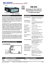
A Wide Scalable Range, 4-20 mA Process Meter.
CM-35XT
Loop-Powered Panel Meter
The CM-35XT is specially designed to simplify in stal la tion,
cali bra tion and scaling. Deriving its operating power from the
current loop, this meter require no external power supply. The
CM-35XT is a functional replacement for the now obsoleted
CM-35X meter.
The meter feature Display Hold, Display Test and Auto-
Polarity Indication. The polarity indication may be dis abled
or re versed by repositioning jumper clips on internal header
pins. Another fea ture of the meters is the
41/2
digit LCD
display which provides for a non-active trailing dummy zero
or a °C/°F de scrip tor. De scrip tor indication may be dis abled
or re-programmed by re po si tion ing jumper clips on internal
header pins.
Input Configuration: ............. Series connection to 4-20mA DC
current loop
Full Scale Ranges: ............... Standard meter is ad just able to any
scal ing between -1999 to +1999 or
-19990 to +19990 with the dummy zero
enabled
Input Impedance: .................. 5.1 Volts drop, plus 70.8Ω
(equivalent to 6.5V Max i mum @ 20mA)
Maximum Overcurrent: ........ 200mA continuous
A/D Converter: ...................... 12 bit dual slope
Accuracy: .............................. ± (0.05% of reading + 2 dig its)
Maximum Resolution: .......... ± 1999 counts
Gain Temp. Coefficient: ....... 0.2 counts/˚C typical
Zero Temp. Coefficient: ...... 0.15 counts/˚C typical
Conversion Rate: .................. 3 readings per second
Display:.................................. 0.48" Liquid Crystal Dis play (LCD)
Descriptors: .......................... Header programmable trailing dummy
zero, ˚C or ˚F
Polarity: ................................. Automatically displays either "+"or "-";
header programmable polarity disable
and reversal
Decimal Selection: ............... User programmable to three positions
Over-range Indication: ......... When input exceeds full scale on any
range being used, most significant "1"
digit and polarity symbol are displayed
with all other digits blank.
Power Supply: .......................NO SEPARATE POWER SUP PLY IS
REQUIRED; as the unit derives its pow er
from the 4-20mA current loop signal
Operating Temperature: ....... -20˚C to +50˚C
Storage Temperature: .......... -20˚C to +70˚C
Relative Humidity: ................ 95% (non condensing)
Case Dimensions: ................ Bezel 2.752” x 1.165” (69.9 x 29.6mm)
Depth behind Bezel 3.33”(84.5mm)
plus 0.662” (16.82mm) for connector
Weight: .................................. 143 gms (5 oz) when packed
1
3
24V External
Loop Supply
Other devices can also be
added to the loop. Fully User Scalable
+
+
_
_
CM-35XT
SPAN
10 to 1500
1400 to 3000
2900 to 4000
Negative
Mid Range
Positive
CAL
ZERO
3 1/2 DIGIT with 0.48” LCD

Texmate, Inc. Tel. (760) 598-9899 • www.texmate.comPage 2 CM-35XT Manual (X07)
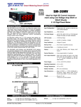
Functional Diagram
Connector Pinouts
Component Layout
Signal Conditioning Component
COM
1XX.X
1X.XX
COM
1.XXX
TEST
0.48" Display
HI
HOLD
LOW
12 Bit
Dual Slope
A to D
Converter
& Display
Driver
GND
+ 5 V – 5 V
1M
Input HI
Input LO
Hold
Te st
Span Range
Header
Descriptor
Header
0.47µF
Span
Pot
25.5
10 to 1500
1400 to 3000
2900 to 4000 1M
45.3
45.3
Zero
Pot
– 5 V
+ 5 V
+5V
+5V
++1.25V
31K6
100 22K
22K
1M
78K7
50K
63K4
16K2
–1.25V
Negative
Zero Offset
Range Header
Mid Range
Positive
CAL
To Display
CM-35XT
48KHz
Clock
Circuit
–5V
Generation
Circuit
–5V
DP Common
DP Common
Display Test
Hold
1XX•X DP
1X•XX DP
1•XXX DP
Input LO
Input HI
10 1500
1400 3000
2900 4000
SPAN RANGE
CALIBRATE
NEGATIVE
MID RANGE
POSITIVE
ZERO RANGE
ZERO RANGE
SPAN RANGE
POLARITY DISPLAY HEADER 338
1.XXX
COM
1X.XX
TEST
LOW HI HOLD
R11
R9
C7
VR1
VR2
R8
R12
C4
IC1
R6
C6
R2A
R2B
R1B
R1A
R13A
R13B
R14B
R15
DESCRIPTOR HEADERR4 R3 C5 C8 R7
Z1 C1 R14A POLARITY DISPLAY
HEADER
SPAN & ZERO RANGE
SELECT HEADER
For most applications where it is not necessary to activate
Display Test or remotely change the selected decimal point,
the three screw terminal blocks supplied with the meter can
be used to connect Current Loop High Input, Current Loop
Low Return and Display Hold Input. For other applications, the
Texmate CM-35XT in ter con nects by means of a stan dard PC
board edge connector having two rows of 10 pins each, spaced
on 0.156" centers. Con nec tors are available from Texmate, or
from almost any connector man u fac tur er.
Pins A, 1 and 3 - Decimal Select: Decimal points may be
blanked as required by carefully scraping off the fine tracks
linking these pins to Decimal Select Common using a pair of
pliers or a small screw driver blade. Re-connect either by linking
the appropriate pins on the connector or by solder-bridging the
junctions located on the PC board edge fingers.
CAUTION: Do not connect the decimal select pins to any pins
other than Decimal Select Common Pins B & 2. Although the
decimals may become activated if an im proper connection is
made to other pins, this will even tu ally cause permanent dam-
age to the LCD display.
Pins B and 2 - Decimal Select Common: Common return pins
for decimal point selection (see CAUTION above).
Pins (D, E) & (4, 5) - Current Loop Low Return: The 4-20mA
current loop is returned from Pins (D, E) & (4, 5). At 4mA the
meter displays the minimum reading. At 20mA the meter dis-
plays the maximum reading.
Pins (F, H) & (6, 7) - Current Loop High Input: The 4-20mA
current loop is applied to Pins (F,H) & (6,7) and returned from
Pins (D, E) & (4, 5). If reverse polarity is applied no damage will
occur; however the meter will not operate (this con di tion should
not be maintained for extended periods).
Pins (J, K) & (8, 9) - Display Hold Input (CMOS com pat ible):
If Pins (J, K) & (8, 9) are left open, the meter will operate in a
free-running mode. When Pins (J, K) & (8, 9) are connected
to Current Loop High Input Pins (D, E) & (4, 5) the meter will
latch up; A/D conversions will continue but the display will not
be updated until Pins (J, K) & (8, 9) are released.
Pins L and 10 - Display Test Input: All numeric display
segments will operate when Pins L and 10 are connected to
Current Loop High Input Pins (D, E) & (4, 5).
Note: Because of the additional current drawn by the circuit in
display test mode, 20mA loop current is required for reliable
in-circuit display test activation.
CAUTION: The Display Test function is only intended for
mo men tary operation. Continuous application of Display Test
will, in time, damage the LCD display.
TEST
12345678910
ABCDE FH JKL
METER REAR WITH PCB EDGE CONNECTOR MOUNTED
(For mounting of screw terminal blocks see rear page)
HOLD
1.XXX
COM
1XX.X
COM
1X.XX
HIGH
LOW
TEST
HOLD
LOW
HIGH
Zero Range Span Range
Decimal Select - 1
Decimal Select Common - 2
Decimal Select - 3
Current Loop High Input
Current Loop Low Return
Display Hold Input
Display Test Input - 10
A- Decimal Select
B - Decimal Select Common
Display Hold Input
L - Display Test Input
J
K
5
4
6
7
8
9
Current Loop High Input
Current Loop Low Return
D
E
F
H
FINE "SCRAPE OFF" TRACKS SOLDER JUNCTION
COMPONENT SIDE PINS SOLDER SIDE PINS
ZERO Potentiometer (Pot)
The ZERO pot when installed is to the left of
the SPAN pots (as viewed from the back of the
meter). Typically it enables the displayed read-
ing to be offset ±1000 counts.
SPAN Potentiometer (Pot)
The 15 turn SPAN pot is always on the right side
(as viewed from the front of the meter). Typical
adjustment is 20% of the input signal range.
Normal
Disabled
Rev
ersed
Polarity Display Header
This header allows the Polarity indication to
be displayed normally, displayed reversed
or to be disabled completely.
Power Supply
The CN-35XT derives its pow er
from the 4-20mA current loop
signal.

Texmate, Inc. Tel. (760) 598-9899 • www.texmate.comCM-35XT Manual (X07) Page 3
Calibration Procedure
Push-On Screw Terminals
Texmate’s exclusive optional Push-On Connectors combine an edge
card connector and a 10 position screw terminal block. Push-On
Connectors are ordered preconfigured for each specific power supply
voltage and each optional power supply available for the CM-Series.
The CM-35XT functions by measuring the voltage drop caused by the
4-20mA signal loop current flowing through a sensing resistor located
inside the meter. The voltage sensed is scaled by an adjustable poten-
tial divider network and converted to a digital reading in counts, shown
by the LCD display.Because the loop current does not go down below
4mA, it is usually necessary to “Zero Offset” the meter reading. This
enables zero or some other appropriate value to be displayed at 4mA,
even though the voltage across the sensing resistor is not zero. The
Zero Offset may be disabled by putting the ZERO RANGE jumper clip
into the CALIBRATE position.
DEFINITION OF SPAN AND ZERO OFFSET
The SPAN is defined here as the total change in counts on the dis-
play when the signal loop current varies from 4mA to 20mA. Note
that decimal points and/or non-active trailing zero are descriptors, and
so are excluded from the calculation. Example: If the required readings
are +190.0 at 20mA
and -30.0 at 4mA, then
the SPAN is (+1900)
minus (-300), or 2200
counts. The ZERO
OFFSET is simply
defined here as the
dis played counts at
4mA. In the exam-
ple above, the ZERO
OFFSET is -300
counts.
CALIBRATION
One header & potentiometer calibrate the span range (the change in
meter reading between 4mA and 20mA). The second header & po ten-
ti ome ter calibrate the zero offset (the meter reading at 4mA). To avoid
interaction between the SPAN RANGE and ZERO RANGE potentiome-
ters, the cali bra tion is performed in the following sequence:
1. Calibrate the SPAN
Place a jumper clip in the CALIBRATE position on the ZERO RANGE
Select Header. This disables the ZERO RANGE po ten ti ome ter.
Depending upon the calculated SPAN, place a jumper clip in the appro-
priate position on the SPAN RANGE header. In the above example, this
would be the position marked 1400-3000.
Apply an input of 4mA to the meter. This input can be derived either from
a Current Calibrator (fig. 1), a 5V DC supply /resistor combination (fig.
2) or from within a current loop, by varying the loop transmitter transduc-
er ap pro pri ately. Adjust the SPAN RANGE potentiometer (R2) to make
the meter display one quarter of the calculated SPAN. In the previous
example the meter would be adjusted to show 2200 ÷ 4, i.e. 550 counts.
Once calibrated, the display changes by 550 counts for a loop current
DESCRIPTOR SELECTION
The CM-35XT is designed with a 3 1/2 digit A/D converter and a 4 1/2
digit display. The right-most digit can be enabled to display different
sym bols such as 0, ˚C or ˚F. This trailing non-active zero can be used to
display en gi neer ing units such
as 15000 rpm in stead of 15.00k
rpm as re quired with 3 1/2 digit
dis plays.
The meter is shipped with the
jump ers in the '0' po si tion. To
dis able all seg ments, remove
all the jumper clips from the
de scrip tor header.
10 - 1500
1400 - 3000
2900 - 4000
SPAN RANGE
CALIBRATE
NEGATIVE
MID RANGE
POSITIVE
ZERO RANGE
10 - 1500
1400 - 3000
2900 - 4000
SPAN RANGE
CALIBRATE
NEGATIVE
MID RANGE
POSITIVE
ZERO RANGE
LOW
HIGH
HOLD
LOW
HIGH
HOLD
CURRENT SOURCE
OR
2 - WIRE
SIMULATOR
MILLIAMMETER
MA
0 - 1.5k 100 Ohms
5V
+-
FRONT OF METER ⇒
Decimal Point Selection
The meter is shipped from the factory with all the
decimal points on. To turn off un wanted deci-
mals, use a pair of long-nosed pliers to scrape
of the fine tracks connecting decimals to decimal
select common (alternatively, use a scalpel or
small screwdriver). Re con nect by soldering
where shown.
RE-BRIDGE
HE
TB-Kit Screw Connectors
change of 4mA. Therefore when the input changes by16mA (i.e. from 4
to 20mA), the display will change by 550 x 4 = 2200 counts.
2. Calibrate the ZERO OFFSET
Remove the ZERO RANGE jumper clip from the CALI BRATE position
and replace it in the NEGATIVE, MID RANGE or POSITIVE position,
depending on whether the required meter reading at 4mA is a large
negative, close to zero, or a large positive reading. In the previous
example, place the jumper clip in the MID RANGE position. Adjust the
ZERO RANGE po ten ti ome ter (R15) to make the meter dis play indicate
the correct reading (-300 in the example).
3. Check the Scaling
Apply loop currents of 4mA and 20mA. Verify that the meter indicates
correctly at both currents. Slight adjustments to the SPAN RANGE and
ZERO RANGE po ten ti ome ters may be re quired.
4. Program Decimal Points and/or Trailing De scrip tor
Refer to the “Decimal Point Selection” section on page 4 for decimal
point programming. Refer to the “Descriptor Se lec tion” section along-
side for de scrip tor header jumper clip positions.
CALIBRATION OF “REVERSE” SCALINGS
“Reverse” scalings that require a more positive reading at 4mA than at
20mA, such as 100.0 at 4mA and 0.0 at 20mA can be accomplished by
calibrating the meter to indicate -1000 at 4mA & 000 at 20mA and then
reversing the display polarity indication. Refer to the “Polarity Display
Header” section on this page for polarity reversal.
SPAN ADJUST Header
Any input Signal Span can then be scaled down
to provide a required Digital Display span from
±19999 (40000 counts) to 0001 (one count).
10 - 1500
1400 - 3000
2900 - 4000
SPAN RANGE
NEGATIVE
MID RANGE
POSITIVE
ZERO RANGE
Part Number: CN-PUSH/CM
Texmate’s individual screw ter mi nal blocks offer a convenient
al ter na tive to edge connectors for many ap pli ca tions, allowing
com plete in stal la tion, con figu ra tion and calibration with out the
need for soldering.
Slide each terminal block over the PCB until the hole aligns.
Insert the re tain ing screw to secure.
Each kit includes: 3 plastic blocks with metal contacts, 4 screws
with spade connectors, 1 metal contact and 3 quick disconnects.
Part Number : TB-KIT
*Not Included

Texmate, Inc. Tel. (760) 598-9899 • www.texmate.comPage 4 CM-35XT Manual (X07)
CM Case Dimensions and Panel Cutouts
Ordering Information
Standard Options for this Model Number
Part Number Description
4BASIC MODEL NUMBER
CM-35XT....... 3.5 digit LCD, Loop Powered, 4-20mA
Special Options and Accessories
Part Number Description
4SPECIAL OPTIONS
(Specify Req. Reading
)
ZRS-CM ...... Non-Std Scale Changes, 3.5 Digit Meters
4ACCESSORIES
CN-L10 ....... PCB Edge Connector, Solder Type, Dual Row 10 Pins
CN-PUSH/CM.. CM Series Push-on Screw Terminal Block Connector
SL.CASERED .. Slim Bezel Case, Red Faceplate w/Mtg Hrdwre
TB-KIT........ Terminal Block Connector Kit (3)
Case Dimensions
TOP VIEW
FRONT VIEW
PANEL CUTOUT SIDE VIEW
16.82mm
0.662in
29.60mm
1.165in
14.50mm
0.571in
64.77mm
2.550 in
24.64mm
0.970in
69.90mm
2.752in
option metal
screw mounting clip
102.36mm
4.030in
84.50mm
3.330in
Edge connector
When extra panel mounting
tightness is required, optional
Screw Mounting Clips can be
purchased seperately and attach
to the sliding mounting side clips
8.50mm
0.335in
2.50mm
0.098in
WARRANTY
Texmate warrants that its products are free from defects in material and workmanship under
normal use and service for a period of one year from date of shipment. Texmate’s obligations
under this warranty are limited to replacement or repair, at its option, at its factory, of any of
the products which shall, within the applicable period after shipment, be returned to Texmate’s
facility, transportation charges pre-paid, and which are, after examination, disclosed to the sat-
isfaction of Texmate to be thus defective. The warranty shall not apply to any equipment which
shall have been repaired or altered, except by Texmate, or which shall have been subjected
to misuse, negligence, or accident. In no case shall Texmate’s liability exceed the original pur-
chase price. The aforementioned provisions do not extend the original warranty period of any
product which has been either repaired or replaced by Texmate.
USER’S RESPONSIBILITY
We are pleased to offer suggestions on the use of our various products either by way of printed
matter or through direct contact with our sales/application engineering staff. However, since
we have no control over the use of our products once they are shipped, NO WARRANTY
WHETHER OF MERCHANTABILITY, FITNESS FOR PURPOSE, OR OTHERWISE is made
beyond the repair, replacement, or refund of purchase price at the sole discretion of Texmate.
Users shall determine the suitability of the proDXct for the intended application before using,
and the users assume all risk and liability whatsoever in connection therewith, regardless
of any of our suggestions or statements as to application or construction. In no event shall
Texmate’s liability, in law or otherwise, be in excess of the purchase price of the product.
Texmate cannot assume responsibility for any circuitry described. No circuit patent or software
licenses are implied. Texmate reserves the right to change circuitry, operating software, speci-
fications, and prices without notice at any time.
CM-35XT Technical Manual Copyright © 2020 Texmate Inc. All rights reserved.
Published by: Texmate Inc. USA. Information in this Technical Manual is
subject to change without notice due to correction or enhancement. The
information described in this manual is proprietary to Texmate, Inc. and may
not be copied, reproduced or transmitted, in whole or in part, in connection
with the design, manufacture, or sale of apparatus, device or private label
product without the express written consent of Texmate, Inc.
1934 Kellogg Ave., Carlsbad, CA 92008
Tel: 1-760-598-9899 • 1-800-TEXMATE
Fax: 1-760-598-9828 • Email: [email protected]
/