Page is loading ...

INNOVA Series
Instruction Manual
Part Number 71-6417
2Aug2012

© 2007 Thermo Fisher Scientific Inc. All rights reserved.
Specifications, terms and pricing are subject to change. Not all products are available in all countries. Please
consult your local sales representative for details.
Thermo Fisher Scientific
Air Quality Instruments
27 Forge Parkway
Franklin, MA 02038
1-508-520-0430
www.thermo.com/aqi

THIS INSTRUMENT IS DESIGNED TO DETECT ONE OR MORE OF
THE FOLLOWING:
FLAMMABLE VAPORS, OXYGEN CONTENT, AND/OR TOXIC GAS AND TO
GIVE WARNING BEFORE THEY REACH HARMFUL CONDITIONS. IN ORDER
TO ENSURE THAT IT WILL WARN OF DANGEROUS CONCENTRATIONS, IT
IS ESSENTIAL THAT THE INSTRUCTIONS IN THIS MANUAL, PARTICULARLY
THOSE CONCERNING START UP, OPERATION, CALIBRATION, AND
MAINTENANCE, BE READ, UNDERSTOOD, AND FOLLOWED.
WARNING
NOTATION CONVENTIONS
Notices are used in this operator's manual to alert you to hazardous condi-
tions to person or instrument and to notify you of additional information.
This operator's manual uses the following notices.
WARNING
Notifies you of potential danger that can result in personal injury
or death.
CAUTION
Notifies you of potential damage to equipment.
NOTE
Notifies you of additional or critical information.

SERVICE LOCATIONS
For additional assistance, service is available from exclusive distributors worldwide.
Contact one of the phone numbers below for product support and technical information
or visit us on the web at www.thermo.com/aqi.
1-866-282-0430 Toll Free
1-508-520-0430 International
WEEE Compliance
This product is required to comply with the European Union’s Waste Electrical & Electronic
Equipment (WEEE) Directive 2002/96/EC. It is marked with the following symbol:
Thermo Fisher Scientific has contracted with one or more recycling/disposal companies
in each EU Member State, and this product should be disposed of or recycled through
them. Further information on Thermo Fisher Scientific’s compliance with these
Directives, the recyclers in your country, and information on Thermo Fisher Scientific
products which may assist the detection of substances subject to the RoHS Directive are
available at: www.thermo.com/WEEERoHS.

Thermo Fisher Scientific Warranty
Warranty
Seller warrants that the Products will operate or perform substantially in
conformance with Seller's published specifications and be free from defects
in material and workmanship, when subjected to normal, proper and
intended usage by properly trained personnel, for the period of time set
forth in the product documentation, published specifications or package
inserts. If a period of time is not specified in Seller’s product
documentation, published specifications or package inserts, the warranty
period shall be one (1) year from the date of shipment to Buyer for
equipment and ninety (90) days for all other products (the "Warranty
Period"). Seller agrees during the Warranty Period, to repair or replace, at
Seller's option, defective Products so as to cause the same to operate in
substantial conformance with said published specifications; provided that
(a) Buyer shall promptly notify Seller in writing upon the discovery of any
defect, which notice shall include the product model and serial number (if
applicable) and details of the warranty claim; (b) after Seller’s review, Seller
will provide Buyer with service data and/or a Return Material
Authorization (“RMA”), which may include biohazard decontamination
procedures and other product-specific handling instructions; and (c) then,
if applicable, Buyer may return the defective Products to Seller with all
costs prepaid by Buyer. Replacement parts may be new or refurbished, at
the election of Seller. All replaced parts shall become the property of Seller.
Shipment to Buyer of repaired or replacement Products shall be made in
accordance with the Delivery provisions of the Seller’s Terms and
Conditions of Sale. Consumables, including but not limited to lamps,
fuses, batteries, bulbs and other such expendable items, are expressly
excluded from the warranty under this warranty.
Notwithstanding the foregoing, Products supplied by Seller that are
obtained by Seller from an original manufacturer or third party supplier are
not warranted by Seller, but Seller agrees to assign to Buyer any warranty
rights in such Product that Seller may have from the original manufacturer
or third party supplier, to the extent such assignment is allowed by such
original manufacturer or third party supplier.
In no event shall Seller have any obligation to make repairs, replacements
or corrections required, in whole or in part, as the result of (i) normal wear
and tear, (ii) accident, disaster or event of force majeure, (iii) misuse, fault
or negligence of or by Buyer, (iv) use of the Products in a manner for which
they were not designed, (v) causes external to the Products such as, but not
limited to, power failure or electrical power surges, (vi) improper storage

Thermo Fisher Scientific Warranty
and handling of the Products or (vii) use of the Products in combination
with equipment or software not supplied by Seller. If Seller determines
that Products for which Buyer has requested warranty services are not
covered by the warranty hereunder, Buyer shall pay or reimburse Seller for
all costs of investigating and responding to such request at Seller's then
prevailing time and materials rates. If Seller provides repair services or
replacement parts that are not covered by the warranty provided in this
warranty, Buyer shall pay Seller therefor at Seller's then prevailing time and
materials rates. ANY INSTALLATION, MAINTENANCE, REPAIR,
SERVICE, RELOCATION OR ALTERATION TO OR OF, OR
OTHER TAMPERING WITH, THE PRODUCTS PERFORMED BY
ANY PERSON OR ENTITY OTHER THAN SELLER WITHOUT
SELLER'S PRIOR WRITTEN APPROVAL, OR ANY USE OF
REPLACEMENT PARTS NOT SUPPLIED BY SELLER, SHALL
IMMEDIATELY VOID AND CANCEL ALL WARRANTIES WITH
RESPECT TO THE AFFECTED PRODUCTS.
THE OBLIGATIONS CREATED BY THIS WARRANTY
STATEMENT TO REPAIR OR REPLACE A DEFECTIVE PRODUCT
SHALL BE THE SOLE REMEDY OF BUYER IN THE EVENT OF A
DEFECTIVE PRODUCT. EXCEPT AS EXPRESSLY PROVIDED IN
THIS WARRANTY STATEMENT, SELLER DISCLAIMS ALL
OTHER WARRANTIES, WHETHER EXPRESS OR IMPLIED, ORAL
OR WRITTEN, WITH RESPECT TO THE PRODUCTS,
INCLUDING WITHOUT LIMITATION ALL IMPLIED
WARRANTIES OF MERCHANTABILITY OR FITNESS FOR ANY
PARTICULAR PURPOSE. SELLER DOES NOT WARRANT THAT
THE PRODUCTS ARE ERROR-FREE OR WILL ACCOMPLISH
ANY PARTICULAR RESULT.

71-6417 vii
TABLE OF CONTENTS
Chapter 1
Introduction
About the Innova Series. . . . . . . . . . . . . . . . . . . . . . . . . . . . . . . . . . . . . 1
Specifications . . . . . . . . . . . . . . . . . . . . . . . . . . . . . . . . . . . . . . . . . . . . . 2
Sensor Specifications . . . . . . . . . . . . . . . . . . . . . . . . . . . . . . . . . . . . . . . 3
Optional Accessories . . . . . . . . . . . . . . . . . . . . . . . . . . . . . . . . . . . . . . . 4
Chapter 2
Start Up & Operation
Preparing for Start Up . . . . . . . . . . . . . . . . . . . . . . . . . . . . . . . . . . . . . . 5
Starting Up the Innova . . . . . . . . . . . . . . . . . . . . . . . . . . . . . . . . . . . . . . 6
Normal Operation . . . . . . . . . . . . . . . . . . . . . . . . . . . . . . . . . . . . . . . . . 7
Turninging Off the Innova . . . . . . . . . . . . . . . . . . . . . . . . . . . . . . . . . . . 8
Performing a Bump Test on Power-Up . . . . . . . . . . . . . . . . . . . . . . . . . 9
Chapter 3
Alarms
Gas Alarms. . . . . . . . . . . . . . . . . . . . . . . . . . . . . . . . . . . . . . . . . . . . . . 11
Battery Alarms . . . . . . . . . . . . . . . . . . . . . . . . . . . . . . . . . . . . . . . . . . . 12
Sensor Alarms . . . . . . . . . . . . . . . . . . . . . . . . . . . . . . . . . . . . . . . . . . . 13
Pump Alarm . . . . . . . . . . . . . . . . . . . . . . . . . . . . . . . . . . . . . . . . . . . . . 14
Datalog Alarm . . . . . . . . . . . . . . . . . . . . . . . . . . . . . . . . . . . . . . . . . . . 15
Temperature Alarm . . . . . . . . . . . . . . . . . . . . . . . . . . . . . . . . . . . . . . . 15
Chapter 4
User Program
About the User Program . . . . . . . . . . . . . . . . . . . . . . . . . . . . . . . . . . . 17
Display Menu. . . . . . . . . . . . . . . . . . . . . . . . . . . . . . . . . . . . . . . . . . . . 18
Accessing Password-Protected Menus. . . . . . . . . . . . . . . . . . . . . . . . . 19
Advanced Features Menu. . . . . . . . . . . . . . . . . . . . . . . . . . . . . . . . . . . 20
Datalog Features Menu . . . . . . . . . . . . . . . . . . . . . . . . . . . . . . . . . . . . 28

viii 71-6417
Innova Series Operator’s Manual
Chapter 5
Calibration
Preparing the Calibration Kit . . . . . . . . . . . . . . . . . . . . . . . . . . . . . . . . 33
Calibrating the Innova . . . . . . . . . . . . . . . . . . . . . . . . . . . . . . . . . . . . . 34
Calibration Alarms. . . . . . . . . . . . . . . . . . . . . . . . . . . . . . . . . . . . . . . . 39
Chapter 6
Maintenance
Preventive Maintenance. . . . . . . . . . . . . . . . . . . . . . . . . . . . . . . . . . . . 41
Trouble Shooting . . . . . . . . . . . . . . . . . . . . . . . . . . . . . . . . . . . . . . . . . 43
Recharging Ni-Cd Batteries . . . . . . . . . . . . . . . . . . . . . . . . . . . . . . . . . 46
Replacing Components . . . . . . . . . . . . . . . . . . . . . . . . . . . . . . . . . . . . 47
Appendix A
Parts List and Accessories . . . . . . . . . . . . . . . . . . . . . . . . . . . . . . . . . . 53
Appendix B
Interference Factors
High Concentration of Combustible Gas . . . . . . . . . . . . . . . . . . . . . . . 57
Relative Combustible Response Table . . . . . . . . . . . . . . . . . . . . . . . . 59
Appendix C
Supplemental Instructions
Innova Land Surveyor . . . . . . . . . . . . . . . . . . . . . . . . . . . . . . . . . . . . . 61
Innova Transformer Gas Tester . . . . . . . . . . . . . . . . . . . . . . . . . . . . . . 65
Soil and Fuel Vapor . . . . . . . . . . . . . . . . . . . . . . . . . . . . . . . . . . . . . . . 69
Calibrating the Innova SV and FV . . . . . . . . . . . . . . . . . . . . . . . . . . . . 71
Innova Soil and Fuel Vapor Monitors Specific Parts List . . . . . . . . . . 75

71-6417 1
Chapter
1
INTRODUCTION
About the Innova Series
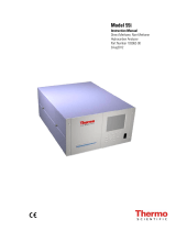
The Innova Series (shown in Figure 1-1) is a line of portable gas monitors
capable of detecting from one to four gases. It continuously computes average
readings for Short Term Exposure Limit (STEL) and Time Weighted Average
(TWA) levels. You can display Peak readings, STEL, and TWA levels on
command. The Alarm circuit alerts you to dangerous gas conditions, low
battery conditions, sensor failure, datalog full, calibration reminder, and
sample-draw pump failures.
Figure 1-1 Innova Series Gas Monitor
The Innova is powered by four “D” size alkaline or nickel-cadmium (NiCd)
batteries. A jack is provided on the Innova so you can connect the external
NiCd battery charger.

2 71-6417
Innova Series Operator’s Manual
Specifications
Table 1-1 lists specifications for the Innova Series gas monitor.
Table 1-1 Specifications for the Innova Series Gas Monitor
Intrinsic Safety Rating
(Area Classification)
Class I, Division 1, Groups A, B, C, and D
Sampling Method Sample-drawing
Response Time Initial: 5 seconds average (with 5-foot hose)
90% complete within 30 seconds (except NH3)
90% complete within 150 seconds (NH3)
Operating Temperature
Storage Temperature
-4° F to 113° F (-20° C to 45° C)
-22° F to 149° F (-30° C to 65° C)
Humidity 0 to 95% relative humidity (RH), non-condensing
Regulatory Approvals UL Classified; CSA Certified, Cenelec
Alarms Audible/visible, coded for gas and trouble. Also a
comfort beep that can be turned off.
Alarm Actions Low flow; low battery; rising gas reading (rising or
falling gas readings for oxygen); rising TWA and
STEL reading (toxic versions only); sensor failure;
temperature; datalog.
Alarm Functions Alarm levels are user-selectable in the Edit Alarms
Screen.
Display Digital liquid crystal display (LCD). Displays up to
four different gases at a time. A back light is available
on demand by momentarily pressing any button.
Power Source Four “D” size alkaline or NiCd batteries.
Battery life Alkaline - 24 hours @ 68° F(20° C)
Ni-Cd - 12 hours @ 68° F(20° C)
Due to the nature of alkaline cells, battery life is greatly
reduced at low temperatures and may be less than two
hours at -15° C. NiCd batteries are recommended for
low temperature applications.
Controls AIR, ON/OFF (power), and RANGE buttons.
Dimensions 10 in. L x 5 in. W x 6 in. H
(254 mm L x 152 mm W x 127 mm H)
Weight 5 pounds (2.25 kg)
Case High-impact, chemical resistant polycarbonate-
polyester plastic with RF-resistant coating.
Standard Accessories 1 Shoulder strap; hose; probe (with filter); operator’s
manual; and quick reference card.
1Innova models for transformer testing include the following standard accessories: dilution fitting, and gas
collection bag.

71-6417 3
Introduction
Sensor Specifications
Table 1-2 Innova Sensor Specifications and Factory Default Settings
Target Gas Display Increments Range Low Alarm High Alarm TWA Alarm STEL Alarm
HC 1% LEL 0 to 100% LEL 10% LEL 50% LEL N/A N/A
HC 0.1% VOL 0 to 5.0% VOL 0.5% VOL 2.5% VOL N/A N/A
HC 20 PPM 0 to 10,000 PPM 1000 PPM 5000 PPM N/A N/A
HC 110 PPM 0 to 1,000 PPM 100 PPM 500 PPM N/A N/A
CH4 21% VOL 0 to 100% VOL 10% VOL 50%VOL N/A N/A
O20.1% VOL 0 to 30.0% VOL 19.5% VOL 23.5% VOL N/A N/A
H2S 1 PPM 0 to 200 PPM 10 PPM 15 PPM 10 PPM 15 PPM
CO 1 PPM 0 to 250 PPM 25 PPM 200 PPM 25 PPM 200 PPM
Cl20.1 PPM 0 to 9.9 PPM 0.5 PPM 1.0 PPM 0.5 PPM 1.0 PPM
HCN 1 PPM 0 to 30 PPM 5 PPM 10 PPM 5 PPM 10 PPM
NH31 PPM 0 to 100 PPM 25 PPM 35 PPM 25 PPM 35 PPM
NO 1 PPM 0 to 100 PPM 25 PPM 75 PPM 25 PPM 75 PPM
NO20.1 PPM 0 to 9.9 PPM 3.0 PPM 5.0 PPM 3.0 PPM 5.0 PPM
PH30.01 PPM 0 to 3.0 PPM 0.3 PPM 1.0 PPM 0.3 PPM 1.0 PPM
SO20.1 PPM 0 to 9.9 PPM 2.0 PPM 5.0 PPM 2.0 PPM 5.0 PPM
1Soil Vapor and Fuel Vapor only.
2Land Surveyor version only.

4 71-6417
Innova Series Operator’s Manual
Optional Accessories
Table 1-3 lists the optional accessories available for the Innova Series gas
monitor. Part numbers for all accessories are in Appendix A, Parts List and
Accessories.
Table 1-3 Innova Series Optional Accessories
Accessory Description
NiCd battery charger Charges NiCd batteries while still in the monitor.
Provides a full charge over an 8-hour period, then drops
to a sustaining rate. Includes an alkaline recognition
feature that prevents you from attempting to recharge
alkaline batteries.
Optional hoses and probes Lengths of hose up to 100 feet are available (except Cl2
versions). Two optional 30-inch probes (aluminum
with dust filter or fiberglass with hydrophobic filter)
are available.
Dilution fitting Used to provide sufficient oxygen to allow proper
response of the hydrocarbon (LEL/ppm) sensor when
sampling inert environments.
Moisture trap Glass-bodied with a pleated paper filter that collects
excess water that is drawn into or condensed in the
sample hose.
Auxiliary hydrophobic
filter
A filter with a water-impervious membrane that
connects between the sampling hose and the Innova’s
inlet fitting.
Remote Buzzer Repeats all audible alarms of the Innova. Plugs into the
remote alarm jack (CHGR). Includes clip to attach to
lapel or other convenient place.
Carrying case A case that holds the Innova and the most commonly
used accessories. The case also has space to hold the
NiCd battery charger.
Confined space kit This carrying case can contain all equipment and the
most commonly used accessories necessary to safely
and accurately calibrate and use the Innova.
Calibration kit A kit consisting of a carrying case containing gas
cylinders, valves, and appropriate fittings to calibrate
the Innova.
Data retrieval kit
(Innova View)
Windows 95/98/NT compatible software necessary to
access the data stored in the Innova (includes serial
cable).

71-6417 5
Chapter
2
START UP & OPERATION
Preparing for Start Up
1. To remove the battery compartment cover, place the Innova upside
down, turn the large screw counterclockwise until it is loose in its
socket, then pull up.
2. Install four “D” size batteries according to the diagram inside the
battery compartment. Make sure that the battery polarities are
correctly oriented.
NOTE
Make sure the slide switch at the bottom of the battery compartment is
set to “ALK” for alkaline or “NI-CAD” for NiCd batteries, see
Chapter 6, Maintenance, Figure 6-1, Innova Battery Compartment.
3. Replace the battery compartment cover and turn the screw clockwise.
Tighten snugly to compress the gasket and seal the battery compartment.
CAUTION
Some toxic gas sensors require up to 15 minutes to stabilize, after
you install the batteries. If your Innova includes a toxic gas
sensor(s), do not turn on and use the Innova during this period. If
the unit is started up immediately after installing batteries, the
“BIAS” message may appear, see Chapter 6, Maintenance, for
instructions on installing or recharging batteries.
4. Verify that the hydrophobic filter and cotton ball are in good condition
and installed properly in the probe body.
NOTE
For transformer versions, connect the dilution fitting directly to the
disconnect coupler fitting on the front of the monitor, then connect the
10-inch probe to the dilution fitting.
5. Attach the probe to the female disconnect coupler fitting on the sample
hose.
6. Attach the other end of the hose to the female disconnect coupler on
the front of the instrument.

6 71-6417
Innova Series Operator’s Manual
WARNING
Operation of instrument without probe/filter assembly attached
will result in pump damage and possible impaired performance.
Do not operate without probe/filter assembly attached.
Starting Up the Innova
Perform the following steps to start up the Innova and adjust internal circuits
to fresh air readings (demand zero). Please read this entire section before
turning on your Innova.
WARNING
Perform the following procedure in a “fresh air” environment
(environment known to be free of combustible and toxic gases and
of normal oxygen content).
1. If you are using NiCd batteries, make sure the batteries are fully
charged before you continue this procedure.
2. Press and hold the ON/OFF button for one second. The Innova begins
the warm-up period. Several messages appear during the warm-up
period, starting with the model and software version. Other screens
displayed are:
• Battery capacity on a scale from E (empty) to F (full capacity) for
new alkaline or a fully charged battery pack.
• Datalogging time left.
• Settings for High, Warning, STEL, and TWA alarms.
• The CAL DUE # DAYS indicates when the Innova is due for
calibration according to the schedule you accepted in the user
program when enabled.
NOTE
During the warm-up period the Innova determines if the toxic sensors
are properly biased. If the sensors require additional biasing, the screen
continuously displays “BIAS” with alarms instead of the gas reading.
Once the readings fall within acceptable limits, a fixed time-out is
initiated. During this time-out, the display will alternate between
“BIAS” and the sensor(s) reading. If an air adjust is performed during
this time-out period, it will not adjust the sensor(s) that are
experiencing the ‘bias time-out’ but will adjust the other sensors.

71-6417 7
Start Up & Operation
3. When the warm-up is complete, the buzzer will beep, lights will flash
several times, and display will read “WARM UP COMPLETE”.
NOTE
If the bump test is set to “BUMP TST ENABLED” the display will
cue the operator to perform an “AIR ADJUST” and then apply gas,
see Performing a Bump Test on Power-Up at the end of this chapter for
instructions.
4. Hold down the AIR button for 3 seconds until the display counts down
and the bar graph starts to scroll, then the display will read “DONE”
once the “fresh air” reading for all active sensors is complete (20.9%
for oxygen, 0 for all other sensors).
NOTE
After you “AIR ADJUST”, a “XXX” sensor failure may appear on the
display screen, see Chapter 3, Alarms, Sensor Alarms, to respond to
these messages.
Normal Operation
Normal operation is defined as any time after the warm-up period is complete
and the Innova is not alerting you to an alarm or failure.
After warm up is complete, the Innova simultaneously displays the current
gas concentration for all active sensors and the NORM icon. This display
screen is defined as the normal screen. The sensor labels will alternate
between the gas type and unit of measure.
During normal operation, the Innova Series gas monitor simultaneously
monitors for all target gases for your configuration of the Innova.
Monitoring Gases
To monitor for the target gas(es), expose the probe to the area to be monitored.
You can leave the Innova monitoring for an entire workday. The Innova
monitors and displays all applicable gas conditions at the same time.
CAUTION
If your Innova includes an Ammonia (NH3), Chlorine (Cl2), Sulfur
Dioxide (SO2), Hydrogen Cyanide (HCN), Nitric Oxide (NO),
Nitrogen Dioxide (NO2), Phosphine (PH3) sensor, avoid moisture
accumulation. The target gas is absorbed by moisture. Inspect the
probe’s hydrophobic filter and cotton ball frequently if you use the
Innova in an environment where moisture might accumulate.

8 71-6417
Innova Series Operator’s Manual
While in normal operation, press any button to illuminate the display screen
back light.
NOTE
If the Comfort Alert is enabled, the Innova will beep and/or blink
every 3 minutes to remind the operator that the unit is turned on and
functioning.This feature can be disabled or enabled by the operator,
see Chapter 4, Alarms, Comfort Alert, for activating/deactivating this
feature.
Changing Combustible Ranges
The RANGE button is used to change the range of combustible gas detected.
The available ranges depend on the version of the instrument, see Chapter 1,
Introduction, Table 1-2. When changing to ppm range the reading is displayed
in the bottom row. If toxic sensor(s) are present the combustible ppm reading
will overwrite the toxic readings. If a toxic sensor(s) goes into an alarm
condition, the instrument will auto range back to the next combustible range,
and allow the toxic sensor(s) to be displayed.
To change the combustible gas range, press and release the RANGE button.
The unit will beep once and switch to the alternate range (e.g. % LEL to ppm).
See Appendix C, Innova Land Surveyor, for operation of the RANGE button
for Land Surveyor models.
If, while operating in the ppm range, the gas concentration exceeds the full
scale range, the Innova will automatically switch to the % LEL (or % VOL if
so configured) range.
Turning Off the Innova
Press and hold the ON/OFF button for 3 seconds. A power off message on the
display screen counts down from 3 seconds. The Innova sounds a pulsing
tone, and the backlight automatically turns on during the power off sequence.
To cancel the power off command, release the ON/OFF button before the
display screen goes blank.
NOTE
The STEL, TWA, maximum, and minimum (for O2) readings are
automatically reset on power down unless the Lunch Break mode is
enabled, see Chapter 4, User Program, Lunch Break Option for more
detail.

71-6417 9
Start Up & Operation
CAUTION
If the Innova will not be used for more than 4 weeks, remove the
batteries from the instrument. Failure to remove the batteries
prior to storage could result in damage to the instrument.
If your Innova uses rechargeable NiCd batteries, the batteries must be fully
charged before each use. When using alkaline batteries, it is best to install
fresh batteries before each use, see Chapter 6, Maintenance, to recharge NiCd
batteries or replace alkaline batteries.
Performing a Bump Test on Power-Up
When the bump test option is set to “BUMP TST ENABLED” the display
alerts the operator to perform a bump test after the warm-up cycle is
complete, see Chapter 4, User Program, Bump Test on Power-Up Option.
To perform the bump test:
1. Assemble the calibration kit, see Chapter 5, Calibration.
2. Turn on the Innova and wait for it to complete the warm-up cycle. The
display will read “AIR ADJUST NOW”. The screen will blink on and
off with alternating lights, prompting the operator to perform a fresh
air adjust.
3. Press and hold the AIR button for three seconds until “DONE”
appears. Once the Innova has been air adjusted, the display will begin
counting down, and prompt the operator to “APPLY GAS”,
alternating with “BUMP TEST”. An audible beep will sound.
NOTE
If an air adjust is not performed within 30 seconds, a “BUMP TEST
INCOMPLETE” message appears and the buzzer beeps on and off for
three seconds. The Innova will return to the normal operating mode.
4. Attach the tubing from the regulator to the probe tube, the Innova will
draw gas from the cylinder.
5. The Innova should respond to the detected gas and beep to indicate that
a Bump Test is being performed. All gas levels for standard gases are
displayed as in the normal operating mode.
NOTE
If no gas is detected during the “APPLY GAS” countdown, a “BUMP
TEST INCOMPLETE” message appears and the buzzer beeps on and
off for 3 seconds. The Innova will return to normal operating mode.

10 71-6417
Innova Series Operator’s Manual
Once gas is detected a countdown is initiated. During this single beep
countdown the user should visually verify the sensors are responding
correctly.
NOTE
Bump test peak readings are recorded. Events are recorded as “BUMP
TEST COMPLETE” if the Innova detected gas, and “BUMP TEST
ABORTED” if the Innova did not detect gas.
A “BUMP TEST COMPLETE” message will be displayed. Then the
screen will alternate between “REMOVE GAS” and the gas readings.
6. Remove the tubing from the probe.
Once the instrument detects that the gas has been removed the screen
display an “ALARMS SILENCED” message. The alarms will be
silenced for a blind 30 second count.
After the 30 second count has elapsed an “ALARMS ACTIVE”
message will display briefly, audible alarms will be enabled and the
Innova will return to the normal operating mode.
NOTE
If the Innova does not respond properly during the bump test, follow the
instructions in Chapter 5, Calibration, or Chapter 6, Troubleshooting
sections of this manual.
NOTE
For instruments having a toxic sensor other than CO or H2S, calibration
gases are only available in single-gas cylinders. Therefore a multi-step
bump process has been programmed into the bump test routine. First,
the standard sensors are bumped using a multi-gas mixture. Then the
first Toxic sensor is bumped using a single-gas cylinder and repeated if
your unit has a second toxic sensor.
WARNING
Avoid using a gas mixture containing H2S for bump testing an
instrument with Cl2, NH3, NO2 or PH3 sensors.

71-6417 11
Chapter
3
ALARMS
This chapter describes Innova alarm indications, display messages, and
response for the following types of alarms:
• Gas Alarms
• Battery Alarms
• Sensor Alarms
• Pump Alarms
• Datalog Alarms
• Temperature Alarms
Gas Alarms
This section describes alarm indications, display messages, and response to
Low, High, STEL, and TWA gas alarms. The backlight automatically turns on
during all gas alarms.
Gas Alarm Indications
Table 3-1 lists the indications for each type of gas alarm.
Table 3-1 Alarm Indications (Gas Alarms)
Alarm Display Light/Buzzer
Low Gas Alarm Reading flashes slow flashing/pulsing
(once/second)
High Gas Alarm Reading flashes fast flashing/pulsing
(twice/second)
Decreasing O2 Alarm Reading flashes fast flashing/pulsing
Increasing O2 Alarm Reading flashes fast flashing/pulsing
STEL Gas Alarm STEL icon flashing/pulsing
TWA Gas Alarm TWA icon flashing/pulsing

12 71-6417
Innova Series Operator’s Manual
Responding to Gas Alarms
1. Follow the established procedure for the type of gas alarm (Low, High,
STEL or TWA). If a procedure is not in place, establish one that is
appropriate for your application.
2. Reset the alarm circuit. The Innova resets the circuit according to the
alarm reset setting “AUTO RESET” or “MANUAL RESET”, see
Chapter 4, User Program, Alarm Latch option to enter the program and
display and/or update the setting.
• If the alarm reset setting is auto reset, the Innova resets the
applicable alarm circuit after the gas reading falls below the alarm
setting (or rises above for decreasing O2).
• If the alarm reset setting is manual reset, press the→ ON/OFF
button to reset the alarm circuits after the gas reading falls below the
alarm setting (or rises above for decreasing O2).
Battery Alarms
This section describes alarm indications, display messages, and response for
the following battery alarms: Low Battery and Replace Battery. The backlight
automatically turns on during all battery alarms
Battery Alarm Indications.
Responding to Battery Alarms
This section describes response to Low Battery and Replace/Recharge
Battery alarms.
1. For low battery alarm, proceed to step 2 as soon as possible. The
Innova will continue to function properly for approximately 1/2 hour
until the Replace/Recharge Battery screen and alarm sounds. For
battery failure alarm, turn off the Innova immediately. It is not
functioning as a gas detection device.
Table 3-2 Alarm Indications (Battery Alarms)
Alarm Display Light/Buzzer
Low Battery LOW BATTERY double flash/beep (every two minutes)
battery icon flashes
Battery Failure
(ALK)
REPLACE BATTERY constant flash/beep
battery icon steady
Battery Failure
(NiCd)
RECHARGE BATTERY constant flash/beep
battery icon steady
/