Page is loading ...


WARRANTY
The ANRITSU product(s) listed on the title page is (are) warranted
against defects in materials and workmanship for one year from the
date of shipment.
ANRITSU's obligation covers repairing or replacing products which
prove to be defective during the warranty period. Buyers shall prepay
transportation charges for equipment returned to ANRITSU for war-
ranty repairs. Obligation is limited to the original purchaser. ANRITSU
is not liable for consequential damages.
LIMITATION OF WARRANTY
The foregoing warranty does not apply to ANRITSU connectors that
have failed due to normal wear. Also, the warranty does not apply to
defects resulting from improper or inadequate maintenance by the
Buyer, unauthorized modification or misuse, or operation outside the
environmental specifications of the product. No other warranty is ex-
pressed or implied, and the remedies provided herein are the Buyer's
sole and exclusive remedies.
TRADEMARK ACKNOWLEDGEMENTS
MS-DOS, Windows, Windows for Workgroups, Windows NT, and Win-
dows 95 are registered trademarks of the Microsoft Corporation.
Site Master, Site Master 110, Site Master S110, Site Master S111, Site
Master S112, Site Master S113, Site Master 330, Site Master S330, Site
Master S330A, Site Master S331, and Site Master S331A are trade-
marks of ANRITSU Company.
NOTICE
ANRITSU Company has prepared this manual for use by ANRITSU
Company personnel and customers as a guide for the proper installa-
tion, operation and maintenance of ANRITSU Company equipment
and computer programs. The drawings, specifications, and informa-
tion contained herein are the property of ANRITSU Company, and any
unauthorized use or disclosure of these drawings, specifications, and
information is prohibited; they shall not be reproduced, copied, or
used in whole or in part as the basis for manufacture or sale of the
equipment or software programs without the prior written consent of
ANRITSU Company.


Table of Contents
General Information ..........1-1
Introduction..................1-1
Description ..................1-1
Standard Accessories.............1-2
Options ....................1-3
Optional Accessories .............1-3
Performance Specifications .........1-5
Operation ................2-1
Introduction..................2-1
Control Descriptions .............2-1
Test Panel ........................2-1
Keypad .........................2-2
Soft Keys ........................2-6
Remote Operation...................2-22
Operating Procedures............2-22
Making Common Function Selections . . . 2-23
Applying Power ....................2-23
Setting Options ....................2-24
Setting Scale/Limits..................2-24
Determining Remaining Battery Life ........2-25
Making Frequency-Domain Measurements2-26
Return Loss or SWR Measurement ....2-26
Selecting a Frequency Range.............2-26
Performing a Calibration...............2-26
Making a Measurement ...............2-28
Scaling the Display ..................2-29
Adjusting Markers ..................2-29
October1997 10580-00017
Copyright1997,ANRITSUCo. Revision:D

Adjusting a Limit ...................2-30
Saving a Setup.....................2-30
Recalling a Setup ...................2-31
Storing a Display ...................2-31
Recalling a Display ..................2-31
Cable Loss Measurement ..........2-32
Selecting a Frequency Range.............2-32
Performing a Calibration...............2-32
Making a Measurement ...............2-34
Scaling the Display ..................2-34
Adjusting Markers ..................2-34
Adjusting a Limit ...................2-35
Saving a Setup.....................2-36
Recalling a Setup ...................2-36
Storing a Display ...................2-36
Recalling a Display ..................2-36
Making Distance-Domain Measurements . 2-37
Selecting a Frequency Range.............2-37
Performing a Calibration...............2-39
Performing a DTF Measurement ..........2-40
Making Power Measurements .......2-42
Entering Power Monitor Mode ...........2-42
Zeroing the Power Monitor .............2-42
Measuring High Input Power Levels ........2-43
Displaying Power in dBm and Watts ........2-43
Displaying Relative Power ..............2-43
Printing....................2-44
Printer Switch Settings ................2-44
Printing a Screen ...................2-45
Symbols ...................2-46
Self Test ...................2-46
Error Codes .................2-46
Self Test Errors ....................2-46
Range Errors .....................2-46
ii

Replacing the Battery ............2-46
Using the Soft Carrying Case........2-51
Software Tools Program........3-1
Description ..................3-1
Requirements .................3-1
Communication Port Setting.........3-2
Changing COM Port Settings–Windows 3.1 .....3-2
Changing COM Port Settings–Windows 95 .....3-4
Software Installation .............3-6
Plot Capture..................3-7
Multiple trace capture (preferred method)......3-7
Single trace capture ..................3-9
Program Operation .............3-10
Fault Location Software ..........3-11
Smith Chart Software............3-11
Saving a Plot as a Windows Metafile....3-12
Saving Data to a Spreadsheet........3-12
“Drag-n-Drop” ...............3-13
Printing....................3-13
iii/iv

How to Use this Manual
The operation of the Site Master ™ is straightforward and intuitive.
However, you may find it helpful to review the operation of the keys
and menus prior to first-time use.
Descriptions of the keys and menus, along with measurement proce-
dures, are provided in Chapter 2.
First-time users and maintenance supervisors will benefit from perusing
the material in Chapter 1. This chapter describes the instrument and
provides listings of options and performance specifications.
v
Please Recycle
This product contains a rechargeable nickel-
cadmium battery. Spent nickel-cadium bat-
teries are valuable resources, do not throw
them away. Arrange for proper return for re-
cycling in your locality. If you do not have
access to proper disposal methods, return the
battery to your ANRITSU service center.
Service centers will dispose of the unit at no
charge. ANRITSU service centers are listed
in Table 2-4 (page 2-52).

1-0
User's Guide
RF
Det
Site Master S331A
Serial
Interface
External
12V
Battery
Charging
12-15V DC
(45C mA)
MARKER
SAVE
DISPLAY
RECALL
DISPLAY
LIMIT
SAVE
SETUP
RECALL
SETUP
CAL
ENTER
ON
OFF
RUN
HOLD
ESCAPE
CLEAR
AUTO
SCALE
START
CAL
1
2
4
3
5
6
8
9
0
7
Test
Port
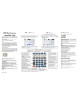
Figure 1-1. Site Master System

Chapter 1
General Information
Introduction
This chapter provides description, specification, and optional accesso-
ries for the Site Master Series instruments. This series has two mem-
bers, as shown below. Throughout this manual, the term Site Master
will refer to the series; whereas, the terms Site Master S330A, S331A
will refer to the applicable individual models.
Model
Frequency Range
S330A 700 to 3300 MHz
S331A 25 to 3300 MHz
Description
The Site Master (Figure 1-1) is a hand held SWR/RL(standing wave
ratio/return loss) and Distance-To-Fault measurement instrument that
includes a built-in synthesized signal source and an optional power
monitor. It uses a keypad to enter data and a liquid crystal display
(LCD) to provide a graphical indication of SWR or RL over the se-
lected frequency range. The Site Master S331A has a built-in
distance-to-fault capability. The Site Master S330A, as well as model
S331A, allows measurement data to be converted to Fault Location via
the companion Software Tools program. The Site Master is capable of
up to two hours of continuous operation from a fully charged internal
battery. It can also be operated from a 12.5 dc source (which will also
1-1
1

simultaneously charge the battery). Built-in energy conservation fea-
tures can be used to extend battery life over an eight-hour work day.
The Site Master is designed for measuring SWR, return loss, or cable
insertion loss and locating faulty RF components in antenna systems.
Power monitoring capability is available as an option. The displayed
trace can be scaled and/or enhanced with settable frequency markers
and/or a limit line. A menu option provides for an audible “beep” when
the limit value is exceeded. To permit use in low-light environments,
the LCD can be back lit using a front panel key.
Standard Accessories
A PC based software program (called Software Tools) provides an on-
line database record for storing measurement data. Site Master Soft-
ware Tools can also convert the Site Master display to a Microsoft
Windows 3.x graphic. Measurements stored in the Site Master internal
memory are down-loaded to the PC using the included serial cable.
This null-modem serial cable connects between the Serial Interface
connector on the Site Master and a Com Port on a DOS/Windows-
based PC. Once stored, the graphic trace can then be displayed, scaled,
and/or enhanced with markers and limit lines. Historical graphs can be
overlaid with current data by using the PC's mouse in “drag-n-drop”
fashion. The underlying data can be extracted and used in spreadsheets
or for other analytical tasks.
The Software Tools program also performs DTF (Distance To Fault) or
Fault Location by clicking on the appropriate icon.
1-2
Chapter 1 General Information

The following items are supplied with the basic hardware.
•
Soft Carrying Case
•
AC-DC Adapter
•
Automotive Cigarette Lighter 12 Volt DC Adapter,
•
3 1/2-inch floppy disk containing the Software Tools program.
This program contains Fault Location (DTF) and Smith Chart
functions
•
Serial Interface Cable (Null Modem Type)
•
One year Warranty (includes battery, firmware, and software)
• User's Guide
• Programming Manual
Options
• Option 5 — Add RF Wattmeter Power Monitor
Optional Accessories
•
N type Standard Short, Part No. SM/STS
•
N type Standard Load, 35 dB, Part No. SM/STL
•
ANRITSU Precision N type Short/Open, Part No. 22N50
•
Site Master Precision N Load, 42 dB, Part No. SM/PL
•
7/16 (m) Precision Open/Short/Load, Part No. 2000-767
•
7/16 (f) Precision Open/Short/Load, Part No. 2000-768
1-3
Chapter 1 General Information

•
Adapter, 7/16 (f) to N (m), Part No. 510-90
•
Adapter, 7/16 (f) to N (f), Part No. 510-91
•
Adapter, 7/16 (m) to N (m), Part No. 510-92
•
Adapter, 7/16 (m) to N (f), Part No. 510-93
•
Test Port Extension Cable, 1.5 meter, Part No. TP/ECN 1.5
•
Test Port Extension Cable, 3.0 meter, Part No. TP/ECN 3.0
•
Test Port Extension Cable, 5.0 meter, Part No. TP/ECN 5.0
•
Test Port Extension Cable, 1.5 meter, Part No. TP/EC 1.5
• Test Port Extension Cable, 3.0 meter, Part No. TP/EC 3.0
•
Test Port Extension Cable, 5.0 meter, Part No. TP/EC 5.0
• RF Detector, 1 to 3000 MHz, N(m) input connector, 50 Ohms,
Part No. 5400-71N50
•
Transit Case for Site Master, Part No. 760-194A
•
HP Deskjet 340 Printer, Part No. 2000-766
•
Serial-to-Parallel Converter Cable (use with the
HP 340 Printer), Part No. 2000-753
•
Seiko DPU-411 Thermal Printer, Part No. 2000-754 or
2000-761
•
Serial Interface Cable (use with the DPU-411 Printer),
Part No. 2000-756
•
Thermal Paper (use with the DPU-411 Printer),
Part No. 2000-755
1-4
Chapter 1 General Information

Performance Specifications
Performance specifications are provided in Table 1-1.
1-5
Chapter 1 General Information
Specifications are valid when the unit is calibrated at ambient tem-
perature after a 5 minute warmup.
Description Value
Frequency Range:
Site Master S330A
Site Master S331A
700 to 3300 MHz
25 to 3300 MHz
Frequency Accuracy (CW Mode) 75 parts per million @25 C*
Frequency Resolution 100 kHz
SWR:
Range
Resolution
1.00 to 65.00
0.01
Return Loss:
Range
Resolution
0.0 to 54.00 dB
0.01 dB
Cable Insertion Loss:
Range
Resolution
0.0 to 20.00 dB
0.01 dB
**Distance-To-Fault (DTF):
Range
Resolution (in meters)
(Rectangular Windowing)
0 to (Resoution x 129)
Where
V
p
is the cable’s relative
propagation velocity.
Table 1-1. Performance Specifications (1 of 2)

1-6
Chapter 1 General Information
Wattmeter Power Monitor:
Range
Offset Range
Resolution
–50.0 to +20 dBm
or
10.0 nW to 100.0 mW
0 to +60.0 dB
0.1 dB
or
0.1 xW
Test Port, Type N 50 Ohms
***Immunity to Interfering signals
up to the level of –15 dBm
Maximum Input (Damage Level):
Test Port, Type N
RF Detector
+22 dBm
+20 dBm
Measurement Accuracy:
Measurement accuracy depends on calibration components. Stan-
dard calibration components have a directivity of 35 dB. Precision
calibration components have a directivity of 42 dB.
Temperature:
Storage
Operation
–20° C to 75° C
0° C to 50° C
Weight: 2.2 pounds
Size: 8x7x2
inches
* ±2 ppm/D°C from 25°C
** Fault location is accomplished by inverse Fourier Transformation of data taken with
the Site Master. Resolution and maximum range depend on the number of frequency
data points, frequency sweep range and relative propagation velocity of the cable being
tested.
*** Immunity measurement is made in CW mode with incoming intefering signal exactly
at the same frequency (worst case situation). Typical immunity is better when swept fre-
quency is used.
Table 1-1. Performance Specifications (2 of 2)

This page is intentionally blank
1-7
Chapter 1 General Information

2-0
RF
Det
Site Master S331A
Serial
Interface
External
12V
Battery
Charging
12-15V DC
(45C mA)
MARKER
SAVE
DISPLAY
RECALL
DISPLAY
LIMIT
SAVE
SETUP
RECALL
SETUP
CAL
ENTER
ON
OFF
PRINT
RUN
HOLD
ESCAPE
CLEAR
AUTO
SCALE
START
CAL
1
2
4
3
5
6
8
9
0
7
Test
Port
Soft Keys
LIMIT
SAVE DISPLAY
ON/OFF
PRINT
RUN
HOLD
RECALL DISPLAY
ENTER
MARKER
RECALL
SETUP
Up/Down
A
CAL
ESCAPE
CLEAR
AUTO SCALE
RF
Detector
Input
Test Port
12.5-15V DC
External
Power
Serial
Interface
Battery
Charging
Back Lighting
START
CAL
SAVE
SETUP
Figure 2-1.
Site Master Controls and Connectors

Chapter 2
Operation
Introduction
This chapter provides a description of each control and describes how
to calibrate the Site Master and make a measurement.
Control Descriptions
Control descriptions are given below; the test panel controls and con-
nectors are listed first. The keypad controls follow and are listed alpha-
betically. Then, the soft keys and menu structure are described using
Figure 2-3 (page 2-7).
Test Panel
12.5-15VDC
(600 mA)
Provides input for battery charging the unit. Input is
12.5 to 15 Vdc @ 600 mA.
Battery
Charging
Indicator light to show that the battery is being
charged. (Indicator automatically shuts off when the
battery is fully charged.)
External
Power
Indicator light to show that the Site Master is being
powered by the external charging unit.
Serial
Interface
Provides an RS232 DB9 interface with a Com Port
on a personal computer (for use with the ANRITSU
Software Tools program). Also provides an interface
2-1
2

to a HP Deskjet 340 printer or a Seiko DPU-411
Thermal printer.
Test
Port
Provides RF output, 50Wimpedance.
RF Det Provides RF detector input for the Power Monitor.
Keypad
Turns the liquid crystal display (LCD) back-lighting
ON or OFF. (Leaving back lighting off conserves
battery power.)
AUTO
SCALE
Automatically scales the display for optimum
resolution.
CAL Opens a calibration menu. Use Up/Down Arrow key
and ENTER key to select a stored calibration (A or
B) or turn CAL off.
ENTER Implements certain menu and key selections.
ESCAPE
CLEAR
Exits the present operation and/or clears the display.
If a parameter is being edited, pressing this key will
clear the value currently being entered and restore the
last valid entry. Pressing this key again will close the
parameter. During normal sweeping, pressing this
key will move up one menu level.
LIMIT Calls up the Scale Menu.
MARKER Calls up the Marker Menu.
ON
OFF
Turns the Site Master on or off. When turned on, the
system state at the last turn-off is restored. If the
2-2
Chapter 2 Operation

ESCAPE/CLEAR key is held down, the factory pre-
set state is restored.
PRINT Prints the current display to the selected printer.
RECALL
DISPLAY
Recalls a previously saved trace from memory loca-
tion 1 through 40. When the key is pressed, “Recall
display:” appears on the display. Select an appropri-
ate number from the keypad and press the ENTER
key to implement.
RECALL
SETUP
Recalls a previously saved setup from memory loca-
tion 0 through 9. When the key is pressed, “Recall
Setup:” appears on the display. Select an appropriate
number from the keypad and press the ENTER key
to implement. Setup 0 recalls the factory preset state.
RUN
HOLD
When in the Hold mode, this key starts the Site Mas-
ter sweeping and provides a Single Sweep Mode
trigger; when in the Run mode, it pauses the sweep.
When in the Hold mode, the hold symbol (Table 2-1,
page 2-47) appears on the left side of the LCD.
(HOLD conserves considerable battery power.)
SAVE
DISPLAY
Saves the displayed trace to 1 of 40 internal
non-volatile memory locations. When the key is
pressed, “Save display:” appears on the display. Se-
lect an appropriate number from the keypad and press
the ENTER key to implement.
To erase saved displays select 0 and press ENTER.
Individual displays may be selected and erased by en-
tering the display number and pressing ENTER. Se-
lecting display 0 will erase all saved displays.
2-3
Chapter 2 Operation

CAUTION:The selected memory location will be over-
written by the SAVE DISPLAY operation. No warning
is given.
SAVE
SETUP
Saves the current system setup to 1 of 9 internal
non-volatile memory locations. When the key is
pressed, “Save Setup:” appears on the display. Select
an appropriate number from the keypad and press the
ENTER key to implement.
CAUTION:The selected memory location will be over-
written by the SAVE SETUP operation. No warning is
given.
START
CAL
Opens a calibration menu. Use the Up/Down Arrow
key and ENTER key to select the location to store
the calibration (A or B) or cancel the command. The
existing calibration in the location chosen will be
overwritten once the calibration is performed.
Follow the text in the message area that instructs you
to do the following:
q
Connect OPEN, Press ENTER
The Site Master then measures the “open” test
port (standard calibration), or the calibration
“open” (precision calibration kit) that you must at-
tach to the end of the test port or transmission line.
2-4
Chapter 2 Operation
/