
1"
"

2"
"
TABLE OF CONTENTS
1. SPECIFICATION & PARTS
IDENTIFICATION .............................................................................3
2. OPERATION & FUNCTION OF
PARTS....................................................................................4, 5
A. Cooling Operation
B. Heating Operation
C. Function of Parts
3. LOCATION
REQUIREMENTS.......................................................................................................5
4. INSTALLATION PROCEDURES ..............................................................................................5,
6
5.
STORAGE.......................................................................................................……………………..6
6. CLEANING ..................................................................................................…………………….6,
7
7. TROUBLESHOOTING GUIDE..............................................................................………..…....7,
8
8. WIRING
DIAGRAM………………………….........................................................………..…….......9
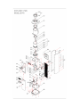
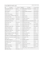
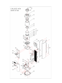
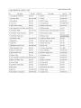
9. EXPLODED VIEW & SERVICE PARTS LIST
A. B14A..................................................................................................................................10,
11
B. B14B.................................................................................................................................12, 13
FOR YOUR SAFETY
Please read the following safety precaution before servicing the watercooler.
1) Check if an electric leakage occurs in the appliance.
2) To prevent electric shock, unplug prior to servicing.

3"
"
3) In case of testing with power on, wear rubber gloves to prevent electric shock.
4) When using an instrument or replacing a part for repairing, check it is applied to
rated voltage current and capacity.
5) Prevent water from flowing into electric elements in mechanical parts.
6) When carrying or tilting the appliance, remove all the objects on it.
7) If the cooling cycle is out of order, contact nearest authorized service center for
maintenance, repair and adjustment.
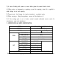
1. SPECIFICATION & PARTS IDENTIFICATION
MODEL
B14A(HOT & COLD)
B14B(COOK & COLD)
DIMENSION
313W×323D×963H(mm)
WEIGHT
16kg
17kg
CONSUMPTION
105W
TEMP CONTROL
AUTO
TANK
Stainless Steel
COLD
CAPACITY
3.0 /h (10 )
CONSUMPTION
405W/465W
PROTECTOR
Heat Limiter
TEMP. CONTROL
Hot Control
TANK
Stainless Steel
HOT
CAPACITY
7.5 /h (85)
ELECTRICAL
220-240V, 50/60Hz. 110-127V, 50/60Hz.
Check the available power supply against the watercooler data plate to assure correct electrical service.

4"
"
2. OPERATION & FUNCTION OF PARTS

5"
"
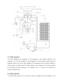
A. Cooling Operation
The vapor refrigerants that compressed to high temperature & high pressure conditions in the
compressor, turn into liquid refrigerant of high temperature and high pressure passing through the
condenser, and then turn into the liquid refrigerants of low temperature and low pressure conditions by
passing through the capillary tubes. The liquid refrigerant of low temperature & low pressure absorbs
the surrounding heat while evaporating in the evaporator. Then, it is sucked in the compressor by
turning into saturated vapor.
B. Heating Operation
The electric heater inside of the hot water tank heats the supplied water. The temperature of hot

6"
"
water is controlled by the hot control at a proper temperature. In case of overheating, the heat limiter
will operate automatically.
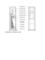
C. Function of Parts
① Compressor: Compresses the vapor refrigerant sucked from the evaporator and discharges it to
condenser
② Condenser: Changes the compressed vapor refrigerant into the liquid refrigerant by cooling.
③ Drier: Removes moisture and dirt inside pipes
④ Capillary tube: Reduces the pressure of liquid refrigerant and evaporates it in the evaporator
under constant pressure.
⑤ Evaporator: Absorbs the surrounding heats while evaporating the liquid refrigerant, cools down
water inside of cold water tank.
⑥ Cold water thermostat: Senses the temperature of cold water tank and controls the electric power
supply to the compressor automatically in order to keep the constant temperature of cold water.
⑦ Over Load Protector (OLP): Protects the compressor and operates when rising up to abnormal
temperature or energizing over current.
⑧ PTC Starter: Starts up the motor of compressor.
⑨ Cold water baffle: Separates the supplied water from cold water, hot water, or room temperature
water respectively.
⑩ Hot tank heater: Heats the supplied room temperature water to hot water.
Hot control: Controls the temperature of hot water at a proper automatically.
Heat limiter: Cuts off the electric power to the heater in case of overheating.
Hot water switch: Supplies or cuts off the electric power to the heater by setting it ON/OFF.
Drain cap: By opening this, you may drain out remaining water in hot water tank when cleaning
or not using cooler for a long period of time.
3. LOCATION REQUIREMENTS
A. Locate cooler in a well ventilated space where temperature is never below 0.
B. Maintain a minimum clearance of 4 inches on sides and rear of cooler for proper ventilation.
C. Make sure installation ground is flat and even. - Unbalanced placement may cause excessive
noise and trembling of the cooler.
D. Coolers are for indoor use only. Keep away from direct sunlight and excessive moisture.
E. Avoid harmful gas or excessive heat.
4. INSTALLATION PROCEDURES
A. Install drip tray below faucet.
B. Thoroughly clean the cooling tank and baffle. Baffle must be in exact place for proper cooling
operation.
CAUTION: IF THE COLD WATER BAFFLE IS REMOVED, COLD WATER WILL NOT BE FORMED NOR

7"
"
DISCHARGED.
C. Put standardized bottle filled with water on top of the product.
Use drinking water only. Filling the unit with any other type of beverages may cause significant
problems.
D. For hot water activation, stay holding down hot faucet handle until water flow is continuous and
clear.
E. Place the hot water switch on the "ON" position.
(Check the available power supply against the cooler specification plate to ensure correct electrical
service.)
CAUTION: FAILURE TO FILL HOT TANK WITH WATER BEFORE SWITCH ON HOT WATER CAN CAUSE
PHYSICAL DAMAGE TO THE COOLER.
F. Cooler will be ready to serve you Cold & Hot water in 30 minute after installation.
G. Hot Water Safety Faucet: A safety faucet deters accidental dispensing of water by toddlers. (Korea,
US patented)
CAUTION: WATER FROM HOT FAUCET IS EXTREMELY HOT AND MAY SCALD.
5. STORAGE
A. Switch off hot water switch. Unplug power cord.
B. Drain hot water by opening faucet. Then, do the same on cold water faucet.
C. Place a bucket behind the drain pipe. By unscrewing the drain cap counter clockwise, drain the
remaining water in the hot water tank. When tank is emptied, dry drain cap and the end of drain
pipe. Close draining pipe with cap.
D. When storing, ensure it stands on its erect position on the flat and even ground. (Do not lay the
product on its sides down or upside down.)
E. When not use for a long period of time, conduct product cleaning before you put in storage.
CAUTION: FAILURE TO ABIDE BY ABOVE PROCEDURE MAY INCUR PHYSICAL DAMAGE ON THE
COOLER.
CAUTION: WATER FROM HOT FAUCET IS EXTREMELY HOT AND MAY SCALD.
6. CLEANING
A. Do the same as A to C procedure for storage.
B. Remove baffle in cold water tank.
C. Remove faucets from the product. Both faucets are disassembled by turning them counter
clockwise.
D. Wear disposable gloves (clean and safe material for drinking water).

8"
"
E. Wash the faucets, drip tray with mild soap and water. Then, rinse them with clean water
immediately.
F. Cleanse interior of cold water tank with a clean dish towel.
Do not use bleach or any cleaning agents containing bleach or chlorine.
G. Assemble drip tray, grid, faucets and baffle.
H. Pour clean water into cold water tank and open cold faucet to flush the entire water trail. Repeat
this step at least three times. Then, close the faucet.
Steps I, J are for Hot & Cold model only.
I. Open hot water faucet. Then, until the water flow from hot water faucet is continuous and clear,
pour clean water into cold water tank. Then, close the faucet.
J. Open drain cap to flush water trail in hot water tank.
Repeat this step at least three times and close the drain cap at the end.
K. Brush out and vacuum the dirt and dust from condenser. Do not use abrasive or wire brush.
L. Follow Installation Procedures to operate the cooler.
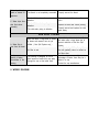
7. TROUBLESHOOTING GUIDE
TROUBLE
POSSIBLE CAUSE
REMEDY
REFRIGERATION SYSTEM
No electric power to outlet.
Turn on electric power outlet.
The thermostat is misadjusted or
defective.
Adjust or replace the thermostat, as
necessary.
The wires leading to the thermostat are
defective or are not connected.
Check the internal wiring.
Make repairs as necessary.
The line voltage is low.
Check the line voltage. It must be at
least 90% of minimum voltage.
The compressor over-load
Protector (OLP) is defective.
Replace the defective over-load
protector.
The starting relay (PTC) is defective.
Replace the starting relay.
A. Compressor does
not run.
The compressor is defective.
Replace the compressor.
Return cooler to authorized service
center or factory for repair.
Poor ventilation.
Minimum side & rear clearance 4"
The condenser is dirty or restricted.
Clean the condenser or relocate the
unit to prevent restricting the
condenser.
B. Water is
adequately chilled,
but cooler runs
excessively or
continuously.
The thermostat is defective. (the
contacts are shorted or the control is
not adjusted properly)
Replace or adjust the thermostat as
necessary.

9"
"
The ambient temperature is high.
It is normal for the cooler to run
continuously at high ambient
temperatures.
There has been a substantial loss in
the sealed system's charge of
refrigerant.
If refrigerant leak is suspected, return
cooler to authorized service center or
factory for repair.
C. The cooler
compressor runs
continuously, but I
do not have cold
water.
The compressor is defective.
Same as above.
HOT WATER SYSTEM
If cooler equipped with hot water
switch may be OFF.
Turn the hot water switch ON.
There is a loose or broken wire
connection in the hot water system.
Identify the loose or broken wire
connection, repair as necessary.
The hot control is defective.
Replace the hot control.
The heat limiter is "ON".
Push "Reset" button of heat limiter.
A. The hot water is
not hot.
The hot tank heater is defective.
Replaced the hot tank heater or hot
tank assembly.
Usage of the hot water system is
greater than its capacity.
Inform the customer of the hot water
system's maximum capacity.
B. The hot water is
hot, but not hot
enough.
The hot control is defective.
Replace hot control.
Hot water flow is designed to flow
slowly than cold and cook water to
prevent splashing.
Advice the customer of this safety
feature.
Defective faucet.
Replace faucet.
C. The hot water
flows slowly or not
at all.
Hot tank plugged with mineral deposits.
De-lime tank.
D. Hot tank is noisy.
The hot tank heater is caked with
mineral deposits.
Slight boiling sound normal during
heating cycle. De-lime tank.
NOISE
The cooler is not level.
The cooler must be leveled.
Place the cooler on even surface.
A section of the tubing inside the
cooler is touching other parts of cooler,
causing noise to be generated due to
vibration.
Adjust position of the tubing to make
sure it is not in contact with any other
parts.
Check the connection of the fixed
screws.
Completely connect the fixed screws.
A. There is
excessive noise
coming from the
cooler, but it is
otherwise operating
normally.
The compressor's operation is noisy
because of inherent conditions.
Advise the customer of the cooler's
normal operating sounds.
WATER LEAKAGE
A. Water drips from
faucet.
The faucet body packing and spring is
defective.
Press down the faucet lever several
times.
Replace faucet assembly.

10"
"
B. Leakage through
inside or outside of
appliance.
The faucet is not completely connected.
Properly connect the faucet.
The dual float valves elbow union is
defective.
Replace the dual float valves elbow
union.
The dual float valve’s packing is
defective.
Replace the dual float valves packing.
C. Water drips from
dual float valves
assembly.
The cold water piping is defective.
Properly connect and replace the cold
water piping.
NON SPILL SYSTEM
User has taken a large draw or series
of draws and reservoir has not yet
refilled. ( Non Spill System only )
Wait until the cold water tank is filled
with water after a large draw due to
inherent restriction of the Non Spill
System.
A. Water flow is
slow from all faucet.
Air filter is wet.
Allow filter to dry. Airflow through the
filter will gradually return to normal as
the filters dries.
B. An excessive
quantity of water
accumulates in the
housing.
The housing is designed to hold a
small amount of water that may seep
through the cap at the bottle neck.
If problem happens on a high
percentage of cooler, there may be a
defect in a cap.
Contact the cap manufacturer.
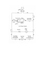
8. WIRING DIAGRAM

11"
"

12"
"

13"
"

14"
"

15"
"
-
 1
1
-
 2
2
-
 3
3
-
 4
4
-
 5
5
-
 6
6
-
 7
7
-
 8
8
-
 9
9
-
 10
10
-
 11
11
-
 12
12
-
 13
13
-
 14
14
-
 15
15


Clover b9a User manual
- Type
- User manual
Ask a question and I''ll find the answer in the document
Finding information in a document is now easier with AI
Related papers
Other documents
-
 Aqua Cooler ODYSSEY SERIES User and Care Manual
-
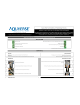 Aquverse 5ph Installation And Troubleshooting Instructions
-
Arctic King ABDA049AS User manual
-
Summit SBC582BNK User manual
-
WaterLogic WL400 Series Operating, Installation And Service Manual
-
-
A.O. Smith Effex GAHH-40 User manual
-
State Industries 317998-002 User manual
-
Aquverse A6000-K Installation guide
-
A.O. Smith GAHH Installation Instructions And Use & Care Manual

