Page is loading ...

WARNING
Read and follow all warnings and cautions printed
on the tow vehicle’s battery. Place 15 Amp fuse in
fuse holder connected to red wire. Place 30 Amp
fuse in fuse holder connected to black wire.
10. Determine a suitable mounting point on the tow
vehicle for the Electric Brake Control Harness.
11. Reconnect the vehicle’s Negative (-) battery cable.
WARNING
All connections must be complete for the T-One
®
T-Connector to function properly. Test and verify
installation with a test light or trailer once installed.
For initial test, reset vehicle electrical system by
temporarily removing the key from the ignition.
12. Secure the remainder of the harness with the cable
ties provided, to prevent damage or rattling and
being careful to avoid any areas that would pinch,
cut or melt the wire.
13. Reinstall the threshold, storage covers, floor covering
and other items removed during installation,
being careful not to pinch or cut the wires.
WARNING
Overloading circuit can cause fires. DO NOT
exceed lower of vehicle manufacturer rating or:
• Max. stop/turn/backup light: 2 per side (4.2 amps)
• Max. tail lights: (7.5 amps)
• Max. 7 Way 12 Volt +: (30 amps)
Read vehicle’s owners manual & instruction sheet
for additional information.
ENGLISH
TOOLS REQUIRED:
Trim Panel Remover, 10mm Socket &
Ratchet or 10mm Wrench, Drill (3/32” Drill Bit),
1/4” Socket, Wire Crimpers, Wire Cutters,
Philips Head Screwdriver, Test-Probe
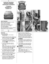
1. Open rear door and remove the access panel doors
on both sides to access vehicle’s wiring connectors
d
. Several trim panel fasteners will need to be
removed to remove the panels
e
.
2. There will be connection points matching the ends
of the T-One
®
T-Connector adapter on the back of
each of the vehicle taillight housings. Disconnect
the wire harness
f
.
3. Beginning on the driver’s side, plug the
T-Connector harness containing the yellow wire
in between the vehicle’s mating connectors.
NOTE
Be careful not to damage the locking tabs and be
sure that connectors are fully inserted with locking
tabs in place.
4. On the Driver’s side route the T-One
®
T-Connector
end with the green wire up through the trim panel
access hole, across the top threshold, & through the
passenger trim panel access hole
g
. Repeat step
2 for the passenger’s side using the T-Connector
containing the green wire.
NOTE
For ease of installation attach harness
(two connectors) to fish wire and carefully
pull toward passenger side.
5. Locate the existing ground stud
h
. Attach the
white wire with the ring terminal and re-tighten.
6. On the Driver’s side, mount the T-One
®
module using the double-sided tape provided.
WARNING
Make sure module is mounted so that the epoxy
side of the module is pointed towards the ground
to prevent any water buildup.
7. Determine 7-Way mounting location. Route the
harness containing the 7 wires down the opening
behind the taillight on the driver’s side. Finish pulling
the harness through the grommet to the exterior of
the vehicle and to 7-Way mounting location
i
.
NOTE
Yellow wire = Reverse function. See diagram for
wire locations
j
.
8. Route the power wire for T-One
®
module and the
power wire for the 7-Way. Following the green
wire from step 4, route the three wires with black
sheathing up to upper vehicle channel
k
. Continue
routing along vehicle channel to the pillar near
the driver’s door. Route down the pillar, along
step in driver’s side doorway and to the battery
l
.
The battery is located under the floor covering,
directly under the steering wheel
m
.
9. Disconnect the vehicle’s Negative (-) battery
cable.Using the fuse holders, ring terminals
and butt connectors secure wires to the vehicle’s
Positive (+) battery cable.
• RED WIRE = 15 amp Fuse Holder
• BLACK WIRE = 30 amp Fuse Holder
• BLUE WIRE = Electric Brake Control
Harness BLUE WIRE
• Electric Brake Control Harness
BLACK WIRE = 30 amp Fuse Holder
• Electric Brake Control Harness
WHITE WIRE = Negative (-) Battery Terminal.
• Electric Brake Control Harness
RED WIRE = Nagative Side of Brake Switch
Installation Instructions
Directives de Montage
Instrucciones de Instalación
7-Way Prep Kit
7-Way Kit de Préparation
7 Vías Kit de Preparación
22112-037 Rev. A 8/11/2014
READ THIS FIRST:
Read and follow all vehicle warnings and installation
instructions before beginning installation. Wear safety
glasses and use all safety precautions during installation.
LISEZ CECI EN PREMIER:
Lire et observer toutes les consignes de sécurité et les
instructions avant de commencer l’installation. Durant
l’installation, veiller à toujours porter des lunettes de
protection et respecter les mesures de sécurité.
LEA ESTO PRIMERO:
Lea y siga todas las advertencias e instrucciones de
instalación del vehículo antes de empezar la instalación.
Use gafas de seguridad y todas las precauciones de
seguridad durante la instalación.
PAGE 1 OF 3
Ram Promaster
k l
m
g
i
ed
f
h
j
7-WAY CONNECTOR
CAR END
As viewed from core back side where
wires are attached with screws.
YELLOW
BLACK
BLUE
BROWN
GREEN
WHITE
RED
/