Page is loading ...

USER'SUSER'S
MANUALMANUAL
AM91RS
AMPROBE
A United Dominion Company

1
1) SAFETY
This manual contains information and warnings that must be followed for operating the
meter safely and maintaining the meter in a safe operating condition. If the meter is used
in a manner not specified by the manufacturer, the protection provided by the meter may
be impaired. The meter is intended only for indoor use.
The meter meets the requirements for double insulation to IEC61010-1(1995), EN61010-
1(1995), UL3111-1(6.1994), CSA C22.2 NO. 1010-1-92 to terminals:
V/R : Category IV 600V ac and dc, and Category III 1000V dc and 750V ac.
mA/µA : Category III 500V ac, and Category II 300V dc.
A : Category III 600V ac, and Category II 300V dc.
PER IEC61010 OVERVOLTAGE INSTALLATION CATEGORY
OVERVOLTAGE CATEGORY I
Equipment of OVERVOLTAGE CATEGORY I is equipment for connection to circuits in
which measures are taken to limit the transient overvoltages to an appropriate low level.
Note – Examples include protected electronic circuits.
OVERVOLTAGE CATEGORY II
Equipment of OVERVOLTAGE CATEGORY II is energy-consuming equipment to be
supplied from the fixed installation.
Note – Examples include household, office, and laboratory appliances.
OVERVOLTAGE CATEGORY III
Equipment of OVERVOLTAGE CATEGORY III is equipment in fixed installations.
Note – Examples include switches in the fixed installation and some equipment for
industrial use with permanent connection to the fixed installation.
OVERVOLTAGE CATEGORY IV
Equipment of OVERVOLTAGE CATEGORY IV is for use at the origin of the installation.
Note – Examples include electricity meters and primary over-current protection
equipment.

2
TERMS IN THIS MANUAL
WARNING identifies conditions and actions that could result in serious injury or even
death to the user.
CAUTION identifies conditions and actions that could cause damage or malfunction in
the instrument.
WARNING
To reduce the risk of fire or electric shock, do not expose this product to rain or moisture.
To avoid electrical shock hazard, observe the proper safety precautions when working
with voltages above 60 VDC or 30 VAC rms. These voltage levels pose a potential shock
hazard to the user. Do not touch test lead tips or the circuit being tested while power is
applied to the circuit being measured. Keep your fingers behind the finger guards of the
test leads during measurement. Inspect test leads, connectors, and probes for damaged
insulation or exposed metal before using the instrument. If any defects are found, replace
them immediately. Do not measure any circuit that draws more than the current rating of
the protection fuse. Do not attempt a current measurement where the open circuit voltage
is above the protection fuse voltage rating. Suspected open circuit voltage can be
checked with voltage functions. Never attempt a voltage measurement with the test lead
inserted into the µA/mA or A input jack. Only replace the blown fuse with the proper
rating as specified in this manual.
CAUTION
Disconnect the test leads from the test points before changing functions. Always set the
instrument to the highest range and work downward for an unknown value if you are
using manual ranging mode.
INTERNATIONAL ELECTRICAL SYMBOLS
!!
Caution ! Refer to the explanation in this Manual
Caution ! Risk of electric shock
Earth (Ground)
Double Insulation or Reinforced insulation

3
Fuse
2) ELECTROMAGNETIC COMPATIBILITY (EMC)
The instrument meets EN55022(1994/A1; 1995/Class B) and EN50082-1(1992)

4
3) PRODUCT DESCRIPTION
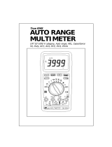
Panel Illustration
1) 4-3/4 digits 40000 counts LCD
display
2) Push-buttons for special
functions & features
3) Selector to turn the Power On
or Off and Select a function
4) Input Jack for 10A (20A for
30sec) current function
5) Input Jack for all functions
EXCEPT current (µA, mA, A)
functions
6) Common (Ground reference)
Input Jack for all functions
7) Input Jack for milli-amp and
micro-amp current functions

5
Analog bar-graph
The analog bar graph provides a visual indication of measurement like a traditional analog
meter needle. It is excellent in detecting faulty contacts, identifying potentiometer clicks,
and indicating signal spikes during adjustments.
DC+AC True RMS
DC+AC True RMS is a term which identifies a DMM that responds accurately to the
total effective RMS value regardless of the waveforms such as: square, sawtooth,
triangle, pulse trains, spikes, as well as distorted waveforms with the presence of
harmonics and DC components. Harmonics and DC components may cause :
1)Overheated transformers, generators and motors to burn out faster than normal
2)Circuit breakers to trip prematurely
3)Fuses to blow
4)Neutrals to overheat due to the triplen harmonics present on the neutral
5)Bus bars and electrical panels to vibrate
Crest Factor
Crest Factor is the ratio of the Crest (instantaneous peak) value to the True RMS value,
and is commonly used to define the dynamic range of a True RMS DMM. A pure
sinusoidal waveform has a Crest Factor of 1.4. A badly distorted sinusoidal waveform
normally has a much higher Crest Factor.
NMRR (Normal Mode Rejection Ratio)
NMRR is the DMM's ability to reject unwanted AC noise effect which can cause
inaccurate DC measurements. NMRR is typically specified in terms of dB (decibel). This
product has a NMRR specification of 60dB at 50 and 60Hz, which means a good
ability to reject the effect of AC noise in DC measurements.
CMRR (Common Mode Rejection Ratio)
Common mode voltage is voltage present on both the COM and VOLTAGE input
terminals of a DMM, with respect to ground. CMRR is the DMM's ability to reject
common mode voltage effect which can cause digit rattle or offset in voltage
measurements. This series has a CMRR specifications of 60dB at DC to 60Hz in
ACV function; and 120dB at DC, 50 and 60Hz in DCV function. If neither NMRR nor
CMRR specification is specified, a DMM's performance will be uncertain.

6
4) OPERATION
ACV, ACV + Hz, & dBm + Hz functions
Defaults at ACV. Press SELECT button momentarily to select ACV + Hz. Press
SELECT button momentarily again to select dBm + Hz. Input sensitivity for Hz varies
automatically with voltage range selected in ACV + Hz function. It is designed especially
for measuring the frequency of high voltage noisy electrical signals.
Note: Default Reference impedance 600Ω will be displayed for 2 seconds before
displaying the dBm + Hz readings. Press dBm-ΩΩ (RANGE) button momentary to select
different reference impedance from 4, 8, 16, 32, 50, 75, 93, 110, 125, 135, 150, 200, 250,
300, 500, 600, 800, 900, 1000, up to 1200Ω. Impedance values will again be displayed for
2 seconds before displaying the dBm + Hz readings.

7
DCV, DC + AC V functions
Defaults at DC. Press SELECT button momentarily to select DC + AC. Analog bar-
graph will be disabled in the DC + AC mode.
Hold
The hold function freezes the display for later view. Press the HOLD button momentarily
to activate and to exit the hold function

8
DC, AC, AC + Hz mV functions
Defaults at DC. Press SELECT button momentarily to select AC. Press SELECT button
momentarily again to select AC + Hz.
DC, AC, AC + Hz Adapter functions
The operation of Adapter function is similar to the mV function. Defaults at DC. Press
SELECT button momentarily to select AC. Press SELECT button momentarily again to
select AC + Hz. Adapter function is of extra high input impedance up to 1000MΩ, and
there is no decimal point on the digital display. It can cope with most voltage output
sensors/ transducers with the highest sensitivity and the least current drain.

9
Hz, % + Hz functions
Defaults at Hz. Press SELECT button momentarily to select % + Hz.
Note: Unlike the AC + Hz function, this high resolution Hz function is set at the highest
input sensitivity to measure digital type electronic signals.
Backlighted display
Press the SELECT button for 1 second or more to turn on and off the display backlight
function. The backlight will also be turned off automatically after 42 seconds to extend
battery life.

10
ΩΩ Resistance, nS + GΩΩ Conductance, Continuity functions
Default at Ω. Press SELECT button momentarily to select nS + GΩ Conductance for
resistance measurement beyond 40MΩ. Press SELECT button momentarily again to
select Continuity function which is convenient for checking wiring connections and
operation of switches. A continuous beep tone indicates a complete wire.
CAUTION
Using resistance and continuity function in a live circuit will produce false results and may
damage the instrument. In many cases the suspected component must be disconnected
from the circuit to obtain an accurate reading

11
Capacitance, Diode test function
Default at . Press SELECT button momentarily to select Diode test function.
CAUTION
Discharge capacitors before making any measurement. Large value capacitors should be
discharged through an appropriate resistance load
Note:
Normal forward voltage drop (forward biased) for a good silicon diode is between 0.400V
to 0.900V. A reading higher than that indicates a leaky diode (defective). A zero reading
indicates a shorted diode (defective). An OL indicates an open diode (defective). Reverse
the test leads connections (reverse biased) across the diode. The digital display shows
OL if the diode is good. Any other readings indicate the diode is resistive or shorted
(defective).

12
µµA, mA, and A Current functions
Default at DC. Press SELECT button momentarily to select AC. Press SELECT button
momentarily again to select AC + Hz. A will be selected automatically when the correct
input jack is plugged in.
Note:
When measuring a 3-phase system, special attention should be taken to the phase to
phase voltage which is significantly higher than the phase to earth voltage. To avoid
exceeding the voltage rating of the protection fuse(s) accidentally, always consider the
phase to phase voltage as the working voltage for the protection fuse(s).
RS232C PC computer interface capabilities
The instrument equips with an optical isolated interface port at the meter back for data
communication. PC interface kit (RS232C optical adapter cable + RS232C software
floppies) is required to connect the meter to the PC computer. The RS232C Data
Recording System software equips with a digital meter, an analog meter, a comparator
meter, and a Data Graphical recorder display. Refer to the README file in the interface
kit for further details.

13
40000 counts high resolution slow mode
Press the 40000 button momentarily to enter the 4-3/4 digit high resolution slow mode.
The digital display updates 1.25 times per second nominal to give you smooth readings
as well as the full accuracy of the meter. Press the 4000 button momentarily to return to
the power up default 3-3/4 digit fast mode. The digital display updates 5 times per second
nominal to give you the maximum measuring speed of the meter.
RECORD mode
Press and hold the RECORD button for one second or more to activate recording mode
with nominal 50ms sampling speed in most functions. The LCD annunciators “R” &
“MAX-MIN AVG” turn on. The meter beeps when new maximum or minimum reading is
updated. Press the button momentarily to read throughout the Maximum (MAX),
Minimum (MIN), Maximum minus Minimum (MAXMIN), and Average (AVG)
readings. Press the button for 1 second or more to exit.
Note:
1. Auto Power Off feature will be disabled automatically in this mode.
2. To retain the readings, press the HOLD button to stop updating the measurement

14
before disconnecting the test leads.

15
CREST capture mode
Press and hold the CREST button for one second or more to activate CREST
(Instantaneous peak hold) mode to capture voltage or current signal duration as short as
0.8ms. This mode is available in DCV, ACV, DCA, & ACA functions. The LCD
annunciators “C” & “MAX” turn on. The meter beeps when new maximum or minimum
reading is updated. Press the button momentarily to read throughout the Maximum
(MAX), Minimum (MIN), and Maximum minus Minimum (MAXMIN) readings. Press
the button for 1 second or more to exit CREST capture mode.
Note:
1. Auto Power Off feature will be disabled automatically in this mode.
2. To retain the readings, press the HOLD button to stop updating the measurement
before disconnecting the test leads.
Manual or Auto-ranging
Press the RANGE button momentarily to select manual-ranging, and the meter will
remain in the range it was in, the LCD annunciator turns off. Press the button
momentarily again to step through the ranges. Press and hold the button for 1 second or
more to resume auto-ranging.

16
Note: Manual ranging feature is not available in Hz function.

17
SORT
TM
mode
Press and hold the SORT button for one second or more to activate SORT
TM
mode. The
LCD annunciators “S” & “MAX-MIN AVG” turn on. SORT
TM
only holds & displays stable
measurement, and counts the event number by the secondary display. The meter beeps
when new stable reading is captured. Press the button momentarily to read throughout
the Maximum (MAX), Minimum (MIN), Maximum minus Minimum (MAXMIN), and
Average (AVG) readings with event numbers out of the captured measurements. Press
the button for 1 second or more to exit.
Note:
1. Auto Power Off feature will be disabled automatically in this mode.
Data Store & Recall
Press the STORE button momentarily to store the display for later view. The LCD
annunciator MEM will blink two times to confirm storage. The memory will remain even
in auto power mode until the rotary switch is switched to the OFF position. Press the
RECALL button momentarily to recall the stored display in any meter function for quick
reference. Press any other button EXCEPT RECALL momentarily to resume
measurement.

18

19
Relative modes
Press the .%.U button momentarily to enter the Relative mode . This allows the
meter to set the displaying reading as the reference value and offset (zero) the display.
The meter consecutive measurements will then be displayed as the relative reading to the
reference value. Practically all displaying readings can be set as the reference value
including MAX/MIN/AVG readings of RECORD & SORT features.
Press the .%.U button momentarily again to show the Relative reading in terms of
percentage change %. The bar-graph will use the reference value as the center zero point
and indicates the + - percentage changes in auto-ranging zoom mode.
Press the .%.U button momentarily again to show the Relative reading in terms of per
unit U. The reference value is considered to be one base unit. The meter consecutive
measurements will then be displayed as the ratio to the base unit.
Press and hold the .%.U button for one second or more to exit.
Auto Power Off (APO)
The Auto Power Off (APO) mode turns the meter off automatically to extend battery life
after approximately 4.5 minutes of no activities. Activities are specified as: 1) Rotary
switch or push button operations, and 2) Significant measuring data readings of above
10% of range. That is, the meter will intelligently avoid entering the APO mode when it is
under normal measurements. To wake up the meter from APO, turn the rotary switch to
an adjacent position.
Note:
1. Always turn the rotary switch to the OFF position when the meter is not in use.
2. For maintenance purpose, press the RANGE button while turning the meter on to
shorten the APO timing to 5 seconds.
Disabling Auto Power Off
Press the 4000 button while turning the meter on to disable the Auto Power Off (APO)
/