Page is loading ...

1
CLEARSPAN
™
JUBILEE TENTS
Revision date: 05.19.09
©2008 ClearSpan™
All Rights Reserved. Reproduction
is prohibited without permission.
Photo may show a different but similar model.
ClearSpan™
Jubilee Frame Tent
STK# DIMENSION
103942 & 104514 30' Wide x 45' Long

CLEARSPAN
™
JUBILEE TENTS
2
Revision date: 05.19.09
YOU MUST READ THIS DOCUMENT BEFORE YOU
BEGIN TO ASSEMBLE THE SHELTER.
Thank you for purchasing this ClearSpan™ shelter. When
properly assembled and maintained, this product will
provide years of reliable service. These instructions include
helpful hints and important information needed to safely
assemble and properly maintain the shelter. Please read
these instructions before you begin.
If you have any questions during the assembly, contact
Customer Service for assistance.
SAFETY PRECAUTIONS
• Wear eye protection.
• Wear head protection.
• Wear gloves when handling metal tubes.
• Use a portable GFCI (Ground Fault Circuit Interrupter)
when working with power tools and cords.
• Do not climb on the shelter or framing during or after
construction.
• Do not occupy the shelter during high winds,
tornadoes, or hurricanes.
• Provide adequate ventilation if the structure is
enclosed.
• Do not store hazardous materials in the shelter.
• Provide proper ingress and egress to prevent
entrapment.
ANCHORING INSTRUCTIONS
Prior to assembling this shelter, please read the anchoring
precautions and instructions included with the kit.
Anchoring instructions are included in the MUST READ
document. You must anchor the shelter after the frame is
assembled and before the cover is installed.
WARNING: The anchor assembly is an integral part
of the shelter construction. Improper anchoring may
cause shelter instability and failure of the structure.
Failing to anchor the shelter properly will void the
manufacturer’s warranty and may cause serious injury
and damage.
LOCATION
Choosing the proper location is an important step before
you begin to assemble the structure.
The following suggestions and precautions will help you
determine whether your selected location is the best
location.
• Never erect the structure under power lines.
• Identify whether underground cables and pipes are
present before preparing the site or anchoring the
structure.
• Location should be away from structures that could
cause snow to drift on or around the building.
• Do not position the shelter where large loads such as
snow and ice, large tree branches, or other overhead
obstacles could fall.
SITE
After choosing a location, proper preparation of the site is
essential. The following site characteristics will help ensure
the integrity of the structure.
• The support structure must be level to properly and
safely erect and anchor the frame.
• If the site is not level, use footing to provide a secure
base for the structure. Pre-cast concrete blocks,
pressure-treated wood posts, or poured footings are all
acceptable when properly used.
• Drainage: Water draining off the structure and from
areas surrounding the site should drain away from the
site to prevent damage to the site, the structure, and
contents of the structure.
WARNING: The individuals assembling this structure
are responsible for designing and furnishing all
temporary bracing, shoring and support needed during
the assembly process. For safety reasons, those who
are not familiar with recognized construction methods
and techniques must seek the help of a qualified
contractor.

3
CLEARSPAN
™
JUBILEE TENTS
Revision date: 05.19.09
ASSEMBLY PROCEDURE
Following the instructions as presented will help ensure
the proper assembly of your shelter. Failing to follow these
steps may result in an improperly assembled and anchored
shelter and will void all warranty and protection the owner is
entitled to.
The steps outlining the assembly process are as follows:
1. Verify that all parts are included in the shipment. Notify
Customer Service for questions or concerns.
2. Read these instructions, the Must Read document, and
all additional documentation included with the shipment
before you begin assembling the shelter.
3. Gather the tools, bracing, ladders (and lifts), and
assistants needed to assemble the shelter.
4. Check the weather before you install the roof cover
and any panels (if equipped). Do not install covers or
panels on a windy or stormy day.
5. Re-evaluate the location and site based on the
information and precautions presented in the
documentation included with the shipment.
6. Lay out the site (if this has not been completed).
7. Assemble the frame components in the order they are
presented in these instructions.
8. Assemble the frame including the bracing (if equipped).
9. Consult the Must Read document for anchoring
comments and instructions.
10. Install, tighten, and secure the end panel (if equipped)
and main cover. This applies to fabric covers that
stretch over the frame assembly.
11. Read the care and maintenance information at the end
of these instructions.
12. Complete and return all warranty information as
instructed.
LIST OF WORDS AND PHRASES
Before you begin, it is important to become familiar with the
words and phrases used in this instruction manual.
These words and phrases are common to most
ClearSpan™ shelters and identify the different parts of
the shelter. (Some are used in this document. Others may
not apply to this particular shelter.) These terms describe
the shipped parts and can also be found on the materials
list/spec sheets included with the shipment. To aid in the
assembly, read through the following definitions before you
begin to assemble your shelter.
• Conduit: An assembly of pipes used to secure the
main cover and end panels (if equipped). Purlins and
some strut assemblies also consist of connected pipes
to form a conduit. Each pipe joint of a conduit assembly
is secured with a self-tapping Tek screw.
• Coupler or Fitting: A part of the frame assembly
where legs, purlins and rafter pipes are inserted and
secured. In most instances, 3-way and 4-way couplers
are used. In some larger applications, couplers are
used to secure the joints of the different rafter sections
during the assembly of the rafters. Some shelters do
not use couplers.
• Foot, Rafter Foot , or Base Plate: The part attached
to and found at the base of the rafter or leg of the
shelter. Depending on the shelter, the foot is an
optional purchase. Some shelters do not offer an
optional foot. Some use 1-way connectors; others use
ground posts.
• Must Read Document: This document includes
building and shelter anchoring instructions, steps for
end wall reinforcement, safety precautions, and notices
and warnings. The Must Read document is sent with all
shelters and buildings. If you did not receive a Must
Read document, contact Customer Service to request
one.
• On-Center: Term used to describe a measurement
taken from the vertical center of the rafter or frame
member to the vertical center of another.
• Purlin or Angled (or Lateral) Bracing: The pipe
assemblies that run perpendicular to the rafters
or framework that supports the main cover. These
assemblies are found on the sides and roof areas of
the assembled frame, are evenly spaced, and typically
run from the front to the back of the shelter.
• Plain or Straight Pipe: A term used to describe a pipe
that has the same diameter or width throughout its
entire length.
• Strut: A strut is usually a length of pipe with two
flattened ends and is used for diagonal bracing of the
shelter frame. A strut is typically secured to the frame
work by special brackets, bolts, and/or clamps.
• Swaged End or Swaged Pipe: The term "swaged''
refers to the tapered end of the pipe or tube. Swaged
ends of a pipe can be inserted into couplers and the
straight ends of other pipes of the same diameter.
• Tek Screw: A self-tapping fastener used to secure pipe
joints and to fasten brackets to rafters.

CLEARSPAN
™
JUBILEE TENTS
4
Revision date: 05.19.09
REQUIRED TOOLS
The following list identifies the main tools needed to
assemble the shelter. Additional tools and supports may be
needed depending on the structure, location, and
application.
• Tape measure or measuring device
• Marker
• Variable speed drill and impact driver (cordless with
extra batteries works best)
• Wrenches or ratchet and socket set (recommended)
• Scissors or utility knife
• Hammers, gloves, and eye protection
• Ladders, work platforms, and other machinery for lifting
designed to work safely at the height of the shelter
• Rope (or straps) for cover installation
• 5/16" Hex key wrench for fittings
UNPACK AND IDENTIFY PARTS
The following steps will ensure that you have all the
necessary parts before you begin to assemble the shelter.
1. Unpack the contents of the shipment and place where
you can easily inventory the parts. Refer to the Bill of
Materials/Spec Sheets.
2. Verify that all parts listed on the Bill of Materials/Spec
Sheets are present. If anything is missing or you have
questions, consult the Pictorial Parts Guide and all
shelter diagrams throughout these instructions for
clarification, or contact Customer Service.
NOTE: At this time, you do not need to open the plastic
bags containing the fasteners (if used).
FRAME OVERVIEW
For a quick overview of this shelter and its components,
consult the Full Frame - Top View and Lower Base - Top
View diagrams at the back of this manual.
Consult the remainder of these instructions for important
details that will help during the construction.
SPECIAL NOTE: Baseboards for Frame
These instructions recommend installing a baseboard
under the legs of the frame. The baseboard runs from the
front to the back of the building.
This baseboard is not included with the shipment and must
be supplied by the customer. Treated or recycled plastic
lumber works well for a baseboard.
The baseboard, when installed properly, helps prevent the
shelter from sinking into the ground when anchored.
Consult these instructions, or contact Customer Service for
additional information regarding baseboards.
PIPE IDENTIFICATION NOTES
The pipe sent with your shelter is identified by length and
diameter. Each pipe part number contains information that
helps describe the pipe. Understanding this information
results in easier assembly of the frame.
For best results and before assembling the various frame
components consisting of different pipe lengths, consult the
information that follows:
EXAMPLE #1: Pipe #190S099D
• The number 190 refers to the pipe diameter, which is
1.90".
• The letter S refers to the tapered or swaged end of the
pipe. This tapered end is inserted into the plain end of
another pipe.
• The 99 indicates the length of the pipe measured end-
to-end.
• The letter D indentifies the pipe as one that includes
holes drilled through the pipe and one or both ends.
These holes are used to secure the pipe to a coupler
using a bolt and nut.
NOTE: Some pipes include the letter P in the part
number, which indicates that the pipe is a plain pipe with a
consistent diameter throughout its length. Such pipes are
not tapered or swaged.
Some pipes are not drilled for mounting bolts. Part numbers
describing these pipes will not include the letter D.
EXAMPLE #2: Pipe #131P063
This part number desribes a plain (P) 63" pipe (63) that is
1.315" in diameter (131) and that is without drilled holes—
no letter D—for mounting bolts.
ATTENTION: Pipes shown above are used for examples
only. Your shelter may not include these pipes.

5
CLEARSPAN
™
JUBILEE TENTS
Revision date: 05.19.09
FA4482B
Tek Screw
The following graphics and photos will help you identify the
different parts of the building. Consult the Frame Overview
for additional details and diagrams. (Some parts are not
shown.)
103933
Corner Coupler
103931
Crown Coupler
100441
Nut Setter
105944
Short Tee
Swivel
10015808
Short Cross
10015608
3-Way Open Corner
FAH007B & FALB01B
Carriage Bolt and Nut
103935
Side Coupler
103936
Hip Coupler

CLEARSPAN
™
JUBILEE TENTS
6
Revision date: 05.19.09
Photo may show a different but similar model.
ClearSpan™
Jubilee Frame Tent
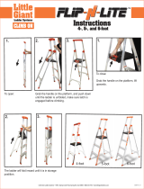
OVERVIEW
This section describes assembling your jubilee frame tent.
For details of each assembly procedure, consult the Frame
Overview and the individual sections of these instructions.
See illustration below to identify main parts of shelter.
1. Layout the site and identify the required parts for each
assembly procedure.
2. Assemble all rafters.
3. Assemble and anchor the frame.
4. Prepare and install the main cover.
For best results, assemble the frame as shown in this
manual.
Side Rafter
Side Rafter
Mid Rafter
Base Rafter
Lower Base Rafter
Ground Level
Hip Rafter
Hip Rafter
Leg

7
CLEARSPAN
™
JUBILEE TENTS
Revision date: 05.19.09
LAY OUT THE BUILDING SITE
After the site is prepared, identify the location of the shelter
corners to help square the frame after it is assembled.
Taking these steps before assembling the shelter saves
time and ensures that the structure is positioned as
desired. The following procedure is a suggested method.
Its use depends on the size of the shelter, shelter
application, the footings, and the method used to anchor
the shelter.
SQUARE THE SITE
1. Identify a corner where a building rafter will be
positioned, drive in a stake, and string a line the exact
width of the building and stake in place. (Width of the
rafter is measured from center-to-center of the rafter
legs.)
2. String a line at least as long as the building from the
first stake at 90°.
NOTE: A transit can be used to ensure an accurate 90°
angle, or the 3-4-5 rule can be used. Refer to diagram.
Using multiples of 3-4-5 such as 6-8-10 or 12-16-20
helps to maintain an accurate 90° angle.
3. After squaring the position of the building and placing
a stake at all corners, string a line between the stakes
to mark the base of the building.
4. Next, paint or mark a line on the ground using the
strings between the stakes as guides.
NOTE: If a baseboard
is used, drill holes
through the board at
evenly-spaced intervals
along the length of
the board. Drive a rod
through each hole and
into the site to prevent
the boards from shifting
and to maintain the
on-center width of the
building.
Actual rafter is not shown.
Baseboard
Rod or Ground
Stake
NOTE: Setting customer-supplied baseboards on the
site in the correct positions is another way to prepare
for the frame assembly.
The baseboards can be "pinned" in place using rods
driven into the site through evenly-spaced holes drilled
in the baseboard. This prevents the baseboards from
shifting during assembly.
Building width is measured on-center.
5. After marking the outline of the building, continue with
the assembly instructions.

CLEARSPAN
™
JUBILEE TENTS
8
Revision date: 05.19.09
ASSEMBLE THE JUBILEE TENT COMPONENTS
NOTE: Assistance is required to assemble the tent.
RAFTER ASSEMBLY
Gather the parts:
• Rafter pipe (#190S099D)
• Rafter pipe (#190S099)
• Rafter pipe (#190P0825)
• Rafter pipe (#190P095D)
• Rafter pipe (#190P030D)
• Rafter pipe (#190P00575)
Each rafter assembly will consist of two (2) pipes. Consult
the chart below to verify the correct pipe lengths.
Rafter Assemblies
Rafter Type Pipe Lengths Number of
Rafters
Base Rafter 190S099D + 190P075D 11
Lower Base Rafter 190S099 + 190P0825 10
Side Rafter 190S099D + 190P095D 6
Mid Rafter 190S099 (2) + 190P00575 2
Hip Rafter 190S099D + 190P030D 16
NOTE: Only the lower base rafters and mid rafters are
assembled with190S099 pipes. All other rafters are
assembled with a 190S099D pipe. Keep the different rafter
types separate for easier assembly.
Rafter Assembly Procedure
1. Select the two (2) pipes needed to assemble a
particular rafter (see chart above) and arrange these on
a flat surface.
2. Slide the swaged portion of each pipe into the end of
the plain pipe that does not have holes. Position drilled
bolt holes at each end of the assembled rafters.
FRAME ASSEMBLY
Gather the parts:
• All rafter assemblies
• Leg pipe (#190P094D)
• Crown Coupler (#103931)
• Corner Coupler (#103933)
• Side Coupler (#103935)
• Hip Coupler (#103936)
• Short Cross (#10015808)
• 3-Way Open Corner (#10015608)
• Short Tee Swivel (#105944)
• 1/4" Carriage Bolts and 1/4" Nuts
• Tek Screws and Duct tape (customer-supplied)
Frame Assembly Procedure
When connecting the rafters to the coupler fittings, use the
first/outermost hole in the coupler fittings to secure each
rafter with a carriage bolt and nut.
When placing a carriage
bolt and nut, position bolt
as shown below to prevent
damage to cover.
ATTENTION: Once the holes of the rafters and the
couplers have been aligned and secured with a carriage
bolt and nut, secure each rafter pipe connection with a Tek
screw. Do not connect with a Tek screw until rafter pipe
has been secured. Make sure the head of the Tek screw is
drilled in a position where it will not contact the main cover.
The following steps are only a suggested procedure for
assembling the frame. Regardless of how you choose to
assemble the tent, however, you must follow Step 6 when
assembling the hip rafters, as it is the only way to properly
fit the frame together.

9
CLEARSPAN
™
JUBILEE TENTS
Revision date: 05.19.09
Step 1: Assemble Top Ridge
a. Slide two (2) short tee swivels onto a base rafter
(171") as shown in picture below.
b. Secure each end of the rafter to a crown coupler as
shown in the diagram to the right. This will serve
as the top ridge pipe of the frame.
c. Secure each connection with a carriage bolt and
nut.
NOTE: Measure each rafter before assembly to
verify that you have selected the correct pipes.
Base Rafter
Crown Coupler
Crown Coupler
Short Tee Swivel
Short Tee Swivel
TOP VIEW
Step 2: Assemble Mid Rafters
a. Connect the two (2) mid rafters (197 3/4") to the
short tee swivels in the middle of the top ridge.
b. Connect the remaining two (2) short tee swivels to
the free ends of the mid rafters.
NOTE: Do not tighten short tee swivels completely.
They may need to be adjusted in the following step.
Mid Rafter
Mid Rafter
Base Rafter
TOP VIEW
FRAME ASSEMBLY (continued)

CLEARSPAN
™
JUBILEE TENTS
10
Revision date: 05.19.09
Step 3: Assemble Mid Section
a. Connect two side rafters (191") and two base
rafters (171").
NOTE: Slide the base rafters through the short tee
swivels before connecting to the side couplers.
b. Secure each connection with a carriage bolt and
nut. This will serve as the mid-section of the frame.
NOTE: Once base rafters are in place, center and
tighten the mid rafters using a 5/16" hex key.
MID-SECTION TOP VIEW
OVERVIEW
Dashed line shows assembly section.
NOTE: Side coupler slots that face inside the mid-section are not used.
Side Rafter
Side Rafter
Side Coupler
Side Coupler
Base Rafter
Base Rafter
FRAME ASSEMBLY (continued)

11
CLEARSPAN
™
JUBILEE TENTS
Revision date: 05.19.09
Step 4: Assemble Side Rafters
a. Connect the remaining side rafters (191") to the
crown couplers.
b. Connect a side coupler to the free end of each
rafter.
c. Secure each connection with a carriage bolt and
nut.
Side Rafter
Side Rafter
Side Coupler
Side Coupler
TOP VIEW
OVERVIEW
Dashed lines show assembly section
FRAME ASSEMBLY (continued)

CLEARSPAN
™
JUBILEE TENTS
12
Revision date: 05.19.09
Step 5: Assemble Base Rafters
a. Connect the base rafters (171") and corner
couplers.
b. Secure each connection with a carriage bolt and
nut.
TOP VIEW
Base Rafters
Base Rafters Base Rafters
Base Rafters
Corner Coupler
OVERVIEW
Dashed line shows assembly section.
FRAME ASSEMBLY (continued)

13
CLEARSPAN
™
JUBILEE TENTS
Revision date: 05.19.09
Step 6: Assemble Corner-to-Crown Coupler
Hip Rafters
a. Connect all hip rafters (126") and hip couplers as
shown in the diagram.
b. Verify that bolts are properly positioned and tight.
FRAME ASSEMBLY (continued)
TOP VIEW
Hip Couplers
Hip Rafters
Corner
Crown Coupler

CLEARSPAN
™
JUBILEE TENTS
14
Revision date: 05.19.09
Step 7: Assemble Side Coupler-to-Side
Coupler Hip Rafters
ATTENTION: Frame will be tight in these areas. The
circled hip rafters will have to be assembled differently.
a. Take the hip rafter pipe apart and connect the
190S099D pipe into the side coupler as shown
below. Secure with a carriage bolt and nut.
b. Connect the 190P030D pipe to the hip coupler.
The connection should look similar to the close-up
picture below. Secure pipe using a bolt and nut.
c. Grabbing the two open ends of the rafter pipes,
forcibly pull apart in order to connect the two
ends together as shown in the diagrams below.
d. Repeat steps a-c for each hip rafter.
e. Check all carriage bolts and nuts to ensure they
are tight and installed properly with the bolt head
toward the cover.
f. Continue by installing the leg pipes.
CAUTION: Keep hands and fingers from between
the pipes when fitting them together.
TOP VIEW
Grab pipes at circled areas
and pull apart and up.
Fit pipes together
as shown.
FRAME ASSEMBLY (continued)
Hip Coupler
Hip Rafter
30"
Side Coupler
Side Coupler
Side Coupler
99"
Secure to side
coupler with a
bolt and nut.
99"
Hip Coupler
Open End
Open End
99"
30"
Secure to hip
coupler with a
bolt and nut.
The angled slots of
the hip couplers will
not be used.

15
CLEARSPAN
™
JUBILEE TENTS
Revision date: 05.19.09
4. After installing and securing the corner legs, install and
secure the remaining legs.
6. Slide each fitting up the leg and position it 8" to 9" from
the corner or side coupler (center-to-center) as shown
in the pictures below. Secure with 5/16" hex key. Set
screws are loosened and retightened when pipes are
added.
Leg and Lower Base Assembly
The following steps will require the assistance of several
people, or a machine designed for lifting. Heavy lifting
is involved. Height assistance may also be required. If
needed, use ladders and/or steady platforms to safely
elevate the frame.
1. Gather the ten (10) sections of #190P094D pipe for the
legs.
2. Starting at two corners, carefully hoist the roof section
of the frame high enough to slide leg pipes, holes first,
into the corner couplers. Align the holes and secure
with a carriage bolt and nut. Support the frame between
the corners with a temporary brace if needed.
3. Move to the opposite side and repeat the step to install
the leg pipes in those corners.
Actual frame may differ from frame shown
Actual frame may differ from frame shown
8" - 9"
8" - 9"
FRAME ASSEMBLY (continued)
5. With all legs installed, lift each leg pipe and slip the
appropriate short cross or 3-way open corner onto the
leg pipe. See the diagram that follows for details.

CLEARSPAN
™
JUBILEE TENTS
16
Revision date: 05.19.09
7. Beginning at a corner, slide each lower base rafter
(178 1/2") into place as they are positioned in the
diagram and work around the frame and back to the
starting corner. Secure each rafter by tightening the
fittings with a 5/16" hex key.
NOTES: Spread the leg pipes apart to fit the lower
base rafters into the fittings.
If needed, remove corner leg to fit the final rafter into
the final fitting, and replace corner leg.
8. Continue by squaring and anchoring the frame.
SQUARE THE ASSEMBLED FRAME
Complete these steps:
1. Square the frame by measuring diagonally corner-
to-corner at ground level and align all legs as shown
below. The frame is square when the two diagonal
measurements are equal.
TOP VIEW
ANCHOR THE FRAME
Once the frame is anchored properly, continue with these
instructions.
WARNING: Securing the rafter mounting feet (if
equipped) to baseboards set on the site is not a
substitute for properly anchoring the shelter. You must
anchor the shelter as described in the MUST READ
document.
FAILING TO PROPERLY ANCHOR THE SHELTER
WILL RESULT IN DAMAGE TO THE SHELTER AND
MAY CAUSE PERSONAL INJURY.
READ THE MUST READ DOCUMENT TO PROPERLY
ANCHOR THE SHELTER.
After anchoring the frame, check the frame for rough
edges as described in the following procedure.
FINAL FRAME CHECK
1. Return to the frame connections and verify that all bolts
are tight. Position bolt heads toward the cover.
2. Verify that all bolts have been inserted in the first/
outermost holes of the coupler fittings.
3. Verify that each rafter splice is secured with a Tek
screw.
4. Verify that each Tek screw is positioned with its head
away from the outside of the frame. Duct tape may be
used on the Tek screws to protect the cover.
5. Inspect the frame for sharp areas that could damage
the cover. If found, file smooth and cover with layers of
duct tape to protect the cover.
6. Verify that all bolts are positioned with the heads to the
outside of the frame. Tape the bolts and rafter joints
before installing the cover.
7. Continue by installing the main cover.
2. Continue by anchoring the frame.
FRAME ASSEMBLY (continued)

17
CLEARSPAN
™
JUBILEE TENTS
Revision date: 05.19.09
PREPARE MAIN COVER
Gather the parts:
• Cover
• Rope (included)
• Ropes long enough to reach over the frame (provided
by customer)
The side flaps of the cover will hang over the base rafters
and are attached to the lower base rafters with rope.
WARNING: To prevent damage to the cover and to
prevent serious personal injury, DO NOT attempt to
install the main cover on a windy day.
ATTACH MAIN COVER
NOTE: Assistance will be required for cover installation.
1. Unfold cover and lay out along one side of frame.
2. Using the grommets (eye-holes) under the side flap, tie
rope to the corners of one side of the cover. The ropes
must be long enough to reach over the frame to the
other side.
3. Toss the ropes over the frame and carefully pull the
cover up onto the frame, making sure the cover does
not snag. One person is required at each rope and one
or more may need to be inside the frame guiding the
cover.
4. Once the main cover is pulled into position, center the
cover on the frame. Temporarily secure the cover to
the frame using a few short sections of rope.
5. Beginning at a corner, thread the end of rope through
a grommet and around the lower base rafter. Use the
lacing pattern shown below as a guide.
6. Pull rope to remove excess slack and tie off.
7. Repeat Steps 5 and 6 for the remaining three sides.
NOTE: To keep cover centered, install all ropes before
the cover is fully tightened.
8. Return to each rope section and tighten.
9. Once the main cover is tied down, secure the side
flaps at each corner. Slide rope through a grommet,
around rafter, back through the other grommet, and tie
together.
Rope
10. Continue by reading the Install Optional Panels section.
If you do not have side panels to install, continue by
reading the Shelter Care and Maintenance information.
Work toward corner

CLEARSPAN
™
JUBILEE TENTS
18
Revision date: 05.19.09
INSTALL OPTIONAL PANELS (if equipped)
Side panels are available for the shelter and provide
additional protection from the elements and other sources
that could damage the contents of the shelter.
To purchase the optional side panels for your shelter,
contact Customer Service at 1.800.245.9881 for additional
information. If you do not have side panels to install,
continue by reading the Shelter Care and Maintenance
information.
WARNING: To prevent serious personal injury or
property damage, DO NOT install the cover on a windy
or stormy day. For longer shelters, additional help is
needed to lift and hold the panels in position.
OPTIONAL INSTALLATION - END and/or SIDE PANELS
NOTE: Optional end and side panels are attached to the
frame with the Ball Tie Downs in the manner illustrated.
Secure the panels to the frame after installing the main
cover.
1. Unpack panels and unfold completely.
2. Take the snugger ball tie downs, feed the stretch cord
through a grommet, and attach the panel to the leg
and lower base rafters. Use one snugger ball for each
grommet.
Optional
Side Panel
1 2 3
NOTE: A space will remain between the cover edge
and the frame as shown in the diagrams.
3. Install all side panels and/or end panels.
Actual frame
may differ from
frame shown.
SHELTER CARE AND MAINTENANCE
Proper care and maintenance of your shelter is important.
Check the following items periodically to properly maintain
your shelter:
• Regularly check the main cover and panels (if
equipped) to see that these remain tight and in proper
repair.
• Check connections and all fasteners to verify that they
remain tight.
• Do not climb or stand on the shelter at anytime.
• Remove debris and objects that may accumulate on
the shelter. Use tools that will not damage the cover
when removing debris.
• Remove snow to prevent excess accumulation. Use
tools that will not damage the cover when removing
snow.
• Check the contents of the shelter to verify that
nothing is touching the cover or the side panels that
could cause damage.
• Check the anchoring system to ensure that all
components are tight and in good repair.
• Replace all worn or damaged parts promptly.
• If the shelter is moved, inspect all parts and
connections before reassembling.
• For replacement or missing parts, call 1.800.245.9881
for assistance.
NOTE: With the exception of Truss Arch buildings,
ClearSpan™ shelters do not have any tested loading
criteria.

19
CLEARSPAN
™
JUBILEE TENTS
Revision date: 05.19.09
Base Rafter
Base Rafter
Base Rafter
Base Rafter
Base Rafter
Base Rafter
Base Rafter
Base Rafter
Hip Rafter
Hip Rafter
Hip Rafter
Hip Rafter
Side RafterSide Rafter
Side Rafter
Side Rafter
Side Rafter
Side Rafter
Mid Rafter
Mid Rafter
Crown Coupler
Short Tee Swivel
Corner Coupler
FULL FRAME
TOP VIEW
Hip Coupler
Hip Coupler
Hip Coupler
Hip Coupler
Side Coupler
Side Coupler

CLEARSPAN
™
JUBILEE TENTS
20
Revision date: 05.19.09
LOWER BASE
TOP VIEW
/