Page is loading ...

BIGASSFANS.COM
es6
EXCEPTIONALLY
ENGINEERED
READ AND SAVE THESE INSTRUCTIONS
À LIRE ET À CONSERVER EN LIEU SÛR
LEA Y CONSERVE ESTAS INSTRUCCIONES

REV. B | 10/09/2020
☑ Prepare Fan Site
Outlet Box: Make sure your outlet box is suitable for fan support. If there is not an
outlet box at the fan location, install one on a ceiling joist or beam.
Concrete Ceiling: Install an anchor hook for the safety cable if required by your
local building and safety code. See the following page for installation details.
Wood Ceiling Joist: Attach the mounting bracket directly to the joist using two
wood screws (not supplied). Recommended: Corrosion-resistant 12-11 x 45 mm hex
head timber screws with seal. If required by local code, mount or embed an outlet
box into the joist. The outlet box must be suitable for fan support.
The mounting/fixing means for attachment to the ceiling such as hooks or other
devices shall be fixed with a sucient strength to withstand four times the
weight of the ceiling fan.
Models and Maximum Weight:
MK-ES61-052306: 25 lb (11.3 kg), MK-ES61-062306: 27 lb (12.1 kg)
Do not use the fan with a dimmer switch.
WARNING: Installation must be in accordance with the requirements set forth
by the National Electrical Code (NEC, United States), ANSI/NFPA 70, and all
national and local codes.
The ground wire must be connected to the supply ground and its length must
be longer than the safety cable.
A means for disconnection must be incorporated in the fixed wiring in
accordance with the wiring rules.
BEFORE YOU START
☑ Turn o Power at Breaker
Input Voltage: 100–277 VAC, 1 Φ, 50/60 Hz
Do not connect the fan to a damaged power
source. Do not attempt to resolve electrical failures
on your own. Contact a licensed electrician if you
are uncomfortable performing electrical work. A
licensed electrician must install the fan if required
by local code.
☑ Gather Tools
Provided with fan

© 2020 DELTA T LLC Ι ALL RIGHTS RESERVED.
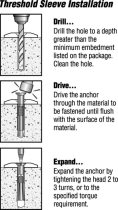
☑ Prepare Concrete Ceiling (if applicable)
Drill three Ø 6 mm holes in the pattern shown. The hole depth should not exceed
40mm. Remove any dust from the holes. Insert three anchor bolts (not supplied)
into the holes. Strike the heads of the anchor bolts with a hammer, ensuring the
bolt sleeves are fl ush with the ceiling surface. Position the mounting bracket on the
anchor bolts. Ensure all three anchor bolts are fully tightened to expand and lock
the anchors.
If required by local building and safety codes, install an anchor hook (not supplied) for
the safety cable. Drill an Ø 8 mm hole for the anchor hook. The hole depth should not
exceed 50 mm. Remove any dust from the hole, and then insert the anchor hook and
fully tighten.
Ø 6 mm
45 mm 43 mm
112 mm
50 mm max
40 mm max

REV. B | 10/09/2020
PARTS AND HARDWARE
EMI filter not shown.
Mounting Bracket
Lower Cover or Light Kit
Mounting Ball
and Wedge
Canopy Screws (4)
Canopy
6 mm Steel Pin
Downrod
Wiring Cover
M6 x 32 mm Bolt
M6 Nut
Airfoils (6)
Wire Connectors
Motor Unit
Wiring and Safety Cable

© 2020 DELTA T LLC Ι ALL RIGHTS RESERVED. 1
INSTALLATION
1. Install downrod and wiring harness
Align holes on downrod with holes on motor bracket. Secure downrod with the M6 x
32mm bolt and M6 nut (Fig. 1.1).
Fig. 1.1
M6 x 32 mm Bolt
M6 Nut
Connect wiring harness from downrod to receptacle from motor unit (Fig. 1.2).
Fig. 1.2
Wiring Harness

REV. B | 10/09/20202
2. Install lower safety cable and ground wire
Install safety cable and ground wire lugs with unpainted screws and lock washers
(Fig.2.1).
Fig. 2.1
Ground Wire
(Green)
Safety Cable
Lock
Washer
Screw
Make sure all hardware is secure, and then gently tug cables at top of downrod to
reduce slack (Fig. 2.2).
Fig. 2.2

© 2020 DELTA T LLC Ι ALL RIGHTS RESERVED. 3
3. Position wiring cover and canopy
Slide wiring cover down downrod, resting it on the fan hub. Make sure no wires are
visible between the cover and fan hub. Slide canopy down downrod, resting it on the
wiring cover (Fig. 3).
Fig. 3
Canopy
Wiring Cover
4. Install mounting ball
Slide mounting ball over downrod (Fig. 4.1).
Insert 6 mm steel pin into hole at top of downrod, and then slide the mounting ball
upward, seating the steel pin in the inner slots (Fig. 4.2).
Insert wedge into mounting ball and secure with screw. Tighten screw enough to
prevent movement between the mounting ball and downrod, but do not over-tighten
(Fig. 4.3).
Fig. 4.1
Mounting Mounting
BallBall
Downrod
6 mm Steel Pin
Screw
Wedge
Fig. 4.2 Fig. 4.3

REV. B | 10/09/20204
5. Install mounting bracket
Disconnect power to fan location before installing mounting bracket.
WARNING: Mount only to an outlet box marked acceptable for fan support.
Secure mounting bracket to mounting structure with suitable hardware (not supplied)
(Fig. 5). Outlet box shown. Your mounting structure may di er from the illustration.
Power supply omitted from mounting bracket illustration for clarity.
Fig. 5
Suitable Mounting Hardware
6. Hang fan
Raise fan to mounting bracket. Align rib in mounting bracket with slot in mounting ball,
position mounting ball, and let fan hang freely (Fig. 6).
Gently twist downrod to ensure it is properly seated and will not move during fan
operation.
Fig. 6
Mounting Ball
Mounting Bracket
Mounting Bracket

© 2020 DELTA T LLC Ι ALL RIGHTS RESERVED. 5
7. Wire fan
Disconnect power to fan location before wiring fan.
Wire fan as shown using the wire connectors (Fig. 7). Attach green ground wire to
mounting bracket with the unpainted screw. Connect wiring harness from power supply
to wiring harness from downrod, making sure that the wiring and safety cable are routed
in the same direction.
Carefully tuck wiring into outlet box or building structure. Ensure wire connectors are
turned upward and that wires are spread apart with grounded conductors on one side
of the outlet box/mounting structure and ungrounded conductors on the other side.
Fig. 7
North America 100–120 V Australia All other regions
AC Hot/L1
Brown
Black Brown or Red Brown
AC Neutral/L2
Blue
White Black or Light Blue Blue
PE/Earth Ground
Green with Yellow
Green or Bare Copper Green with Yellow Green with Yellow
Supply Power Wire Color Chart
AC HOT/L1
BROWN
AC NEUTRAL/
L2
PE/EARTH
GROUND
BLUE
GREEN &
YELLOW
EMI Filter
Power Supply
Wiring Harnesses
Mounting Bracket
Safety
Cable
RED
Wire Connector

REV. B | 10/09/20206
8. Install fan stabilizer (optional, outdoor fans only)
The fan stabilizer is included only if purchased as an outdoor fan accessory.
If you purchased the fan stabilizer kit, fi t stabilizer into notches on top of mounting ball
(Fig. 8.1).
Fig. 8.1
Mounting Ball
Fan Stabilizer
Secure stabilizer plate to stabilizer with the M6 x 70 mm bolt and M6 nut (Fig. 8.2).
Fig. 8.2
M6 Nut
Stabilizer Plate
M6 x 70 mm Bolt

© 2020 DELTA T LLC Ι ALL RIGHTS RESERVED. 7
9. Secure safety cable
Some local safety codes require the safety cable to be secured directly to an existing
part of the building structure (Canada, Singapore). It may be necessary to install
additional structural material to provide attachment points. Check your local safety
code if you are unsure. Contact Customer Service for help.
Mounting Bracket
Loop safety cable around mounting bracket, and then secure it with the shackle (Fig. 9.1).
Fig. 9.1
Shackle
Safety Cable
Anchor Hook
Loop safety cable around anchor hook, and then secure it with the shackle (Fig. 9.2).
Fig. 9.2
Safety Cable
Shackle

REV. B | 10/09/20208
10. Raise canopy
Raise canopy to mounting bracket, aligning the four holes on the canopy with the holes
on the bracket. Secure canopy to mounting bracket with the painted screws (Fig. 10).
Make sure all wires and the safety cable are tucked in the canopy.
Fig. 10
Canopy
Canopy Screw
Building Structure
Loop safety cable around building structure, and then secure it with the shackle (Fig.
9.3). Acceptable building structures include a wooden beam or a metal mounting brace
secured between two beams. In some cases it may be necessary to install additional
structural material to provide attachment points.
Fig. 9.3
Safety Cable
Shackle

© 2020 DELTA T LLC Ι ALL RIGHTS RESERVED. 9
11. Install airfoils
Slide airfoils into slots on sides of motor unit. Install each airfoil on opposite side of fan
from previous airfoil to prevent fan from tilting (Fig. 11.1). Make sure numbered sticker on
each airfoil matches corresponding slot number on bottom of fan. Ensure all airfoils
are fully seated in slots before tightening screws on bottom of fan.
Fig. 11.1
Tighten the six airfoil screws on bottom of fan according to numbered sequence
(Fig. 11.2). When fi nished, repeat tightening sequence. Verify all six screws are fully
tightened by making sure the tabs next to holes 1 and 5 are fl ush with the openings.
Fig. 11.2
Airfoil

REV. B | 10/09/202010
12a. Install lower cover
Align slots on lower cover with tabs on bottom of fan and twist cover clockwise to lock
(Fig. 12.1).
Fig. 12.1
Lower Cover
Light
12b. Install light kit (optional)
CAUTION: To reduce the risk of electric shock, disconnect power to fan before
installing light kit.
Plug light wiring harness into receptacle on bottom of fan. Align slots on light with tabs
on bottom of fan and twist light clockwise to lock (Fig. 12.2).
Fig. 12.2
Use only with light kits marked “Suitable for Use in Wet Locations.”
Use only light kit model 009786. Light Kit Weight: 2.2 lb (998 g)

© 2020 DELTA T LLC Ι ALL RIGHTS RESERVED. 11
For operation, maintenance, and troubleshooting information, visit bigassfans.com/support
Congratulations!
Installation is now complete. Turn on power and test your fan using the remote control.
enables/disables your preferences in the mobile app.
Fan On/O
Adjust Fan Speed
Light On/O
(optional)
Adjust Light Brightness
(optional)

REV. B | 10/09/202012
If you need to remove the light, use a long, thin object such as a small allen wrench or
pen tip to press tab on light. While pressing tab, twist light counterclockwise and slide
down (Fig. 13.2).
Fig. 13.2
Removing the lower cover or light
If you need to remove the lower cover, twist cover counterclockwise and slide down
(Fig. 13.1).
Fig. 13.1

FRANÇAIS

RÉV. B | 10/09/2020
☑ Préparer l'emplacement du ventilateur
Boîte de sortie: Assurez-vous que la boîte de sortie est adéquate pour le support
de ventilateur. S'il n'y a pas de boîte de sortie à l'emplacement du ventilateur,
installez-en une sur une solive de plafond ou une poutre.
Plafond en béton: Installez un crochet d'ancrage pour le câble de sécurité si les
codes de sécurité et de construction locaux l'exigent. Consultez la page suivante
pour connaître les détails d'installation.
Solive de plafond en bois: fixez le support de montage directement à la solive en
utilisant deux vis à bois (non fournies). Recommandé: vis à bois à tête hexagonale
de 12-11 x 45mm résistantes à la corrosion avec joint. Si le code local l'exige,
montez ou encastrez une boîte de sortie dans la solive. La boîte de sortie doit être
adéquate pour le support de ventilateur.
La méthode de montage/fixation pour l'installation au plafond, comme des
crochets ou d'autres dispositifs, doit être fixée avec une force susante pour
supporter quatre fois le poids du ventilateur de plafond.
Modèles et poids maximum:
MK-ES61-052306: 25lb (11,3kg), MK-ES61-062306: 27lb (12,1kg)
N'utilisez pas le ventilateur avec un gradateur.
AVERTISSEMENT: l'installation doit être réalisée conformément aux exigences
établies par le code national de l'électricité (NEC, États-Unis), ANSI/NFPA 70, et
tous les codes nationaux et locaux.
Le fil de terre doit être connecté à la mise à la terre de l'alimentation et sa
longueur doit être supérieure à celle du câble de sécurité.
Il est nécessaire d'intégrer un moyen de déconnexion dans le câble fixe en
conformité avec les règles de câblage.
AVANT DE COMMENCER
☑ Coupez l'alimentation au niveau du disjoncteur
Tension d'entrée: 100–277VCA, 1 Φ, 50/60Hz
Ne connectez pas le ventilateur à une source
d'alimentation endommagée. Ne tentez pas de
résoudre les défaillances électriques par vous-
même. Contactez un électricien certifié si vous
n'êtes pas à l'aise pour réaliser le travail électrique.
Si le code local l'exige, un électricien certifié doit
réaliser l'installation du ventilateur.
☑ Réunir les outils
Fourni avec le ventilateur

© 2020 DELTA T LLC Ι TOUS DROITS RÉSERVÉS.
☑ Préparez un plafond en béton (le cas échéant)
Percez trois trous de 6mm de diamètre selon la disposition illustrée. La profondeur
du trou ne doit pas dépasser 40mm. Retirez toute la poussière des trous. Insérez
trois boulons d'ancrage (non fournis) dans les trous. Frappez la tête des boulons
d'ancrage avec un marteau en vous assurant que les fourreaux de boulon sont
ajustés avec la surface du plafond. Positionnez le support de montage sur les
boulons d'ancrage. Assurez-vous que les trois boulons d'ancrage sont entièrement
serrés pour armer et verrouiller les ancrages.
Si les codes de sécurité et de construction locaux l'exigent, installez un crochet
d'ancrage (non fourni) pour le câble de sécurité. Percez un trou de 8mm de
diamètre pour le crochet d'ancrage. La profondeur du trou ne doit pas dépasser
50mm. Retirez toute poussière du trou, puis insérez le crochet d'ancrage et serrez
complètement.
Ø 6mm
45mm 43mm
112mm
50mm max
40mm max

RÉV. B | 10/09/2020
PIÈCES ET QUINCAILLERIE
Filtre EMI non illustré.
Support de montage
Couvercle inférieur et
ensemble d'éclairage
Rotule et cale
de montage
Vis de couvercle (4)
Couvercle
Goupille en acier
de 6mm
Tige d'extension
Cache-fils
Boulon M6 x 32mm
ÉcrouM6
Pales (6)
Connecteurs
Bloc moteur
Câblage et câble de sécurité
/