Page is loading ...

English
CL20259
HIGH PRESSURE DUCT SERIE H7
www.mundoclima.com
Thank you very much for purchasing our products.
Please read this manual carefully before installing
and using the unit.
MUCHR-96-H7T
Installation and
owner's manual
and information requirements

2
Thank you for selectiong super quality Air Conditiones. To ensure satisfactory operation for many ears to come,
this manual should be read carefully before the installation and before using the air conditioner. After reading,
store it a safe place. Please refer to the manual for questions on use or in the event that any irregularities occur.
This Air Conditioner should be used for hosehold use.
This unit must be installed by a professional according RD 795/2010, RD 1027/2007 and RD 238/2013.
The power supply must be SINGLE-PHASE (one phase (L) and one neutral (N)) with his grounded power (GND))
switch. Any breach of these specifications involve a breach of the warranty conditions provided by the manufacturer.
In line with the company's policy of continual product improvement, the aesthetic and dimensional characteristics,
technical data and accessories of this appliance may be changed without notice.
Read this manual carefully before installind or operating you new air conditioning unit. Make sure to save this
manual for future reference.
or THREE-PHASE (three phase (L1, L2, L3) and one neutral (N) with his grounded power (GND)) and his manual
EU 2016/2281
Information requirements for air-to-air air conditioners ......................
35
Information requirements for heat pumps ............................................
36
CONTENTS
Information requirements (for units > 12kW)
CONTENTS
Installation manual ....................................................................................
3
Owner's manual ......................................................................................
18
Installation and owner's manual
Wired controller ......................................................................................
28

INSTALLATION MANUAL
INVERTER SPLIT-TYPE
ROOM AIR CONDITIONER
The design and specifications are subject to
change without prior notice for product improvement.
Read This Manual:
Inside you will find many helpful hints on how to use and
maintain your air conditioner properly.
Just a little preventative care on your part can save you
a great deal of time and money over the life of your air
conditioner.
You'll find manyanswers to common problems in the
chart of troubleshooting tips. If you review the chart of
Troubleshooting Tips first, you may not need to call for
service.
3
Please read this manual carefully before installing
and using the unit.

PRECAUTIONS
INSTALLATION
INFORMATION
ACCESSORIES
INDOOR UNIT INSTALLATION
OUTDOOR UNIT INSTALLATION
INSTALL THE REFRIGERANT PIPE
CONNECT THE DRAIN PIPE
ELECTRIC WIRING WORK
..................................................... ........ .. ...4.. . ..............
..........................................................5
...................................................................................6
...........................................................7
......................................................11
.................................................13
............................................................15
...............................................................16
CONTENTS
PAGE
Keep this manual
where the operator can easily find them.
Read this manual attentively before starting up the units.
For safety reason the operator must read the following
cautions carefully.
The safety precautions listed here are divided into two categories.
If you do not follow these instructions exactly, the unit may
cause property damage, personal injury or loss of life.
cause minor or moderate property damage, personal injury.
After completing the
installation, make sure that the unit operates
properly during the start-up operation. Please instruct the customer on
how to operate the unit and keep it maintained.Also, inform customers
that they should store this installation manual along with the owner's
manual for future reference.
Be sure only trained and qualified service personnel to install,
repair or service the equipment.
Improper installation, repair, and maintenance may result in
electric shocks, short-circuit, leaks, fire or other damage to the
equipment.
Install according to this installation instructions strictly.
If installation is defective, it will cause water leakage, electrical
shock and fire.
When installing the unit in a small room, take measures
against to keep refrigerant concentration from exceeding
allowable safety limits in the event of refrigerant leakage.
Contact the place of purchase for more information. Excessive
refrigerant in a closed ambient can lead to oxygen deficiency.
Use the attached accessories parts and specified parts for
installation.
otherwise, it will cause the set to fall, water leakage, electrical
shock and fire.
Install at a strong and firm location which is able to withstand
the set's weight.
If the strength is not enough or installation is not properly done,
the set will drop to cause injury.
The appliance must be installed 2.3m above floor.
The appliance shall not be installed in the laundry.
Before obtaining access to terminals, all supply circuits must
be disconnected.
The appliance must be positioned so that the plug is accessible.
The enclosure of the appliance shall be marked by word, or by
symbols, with the direction of the fluid flow.
For electrical work, follow the local national wiring standard,
regulation and these installation instructions. An independent
circuit and single outlet must be used.
If electrical circuit capacity is not enough or defect in electrical
work, it will cause electrical shock or fire.
Use the specified cable and connect tightly and clamp the
cable so that no external force will be acted on the terminal.
If connection or fixing is not perfect, it will cause heat-up or fire
at the connection.
Wiring routing must be properly arranged so that control board
cover is fixed properly.
If control board cover is not fixed perfectly, it will cause heat-up
at connection point of terminal, fire or electrical shock.
If the supply cord is damaged, it must be replaced by the
manufacture or its service agent or a similarly qualified person
in order to avoid a hazard.
An all-pole disconnection switch having a contact separation
of at least 3mm in all poles should be connected in fixed wiring.
When carrying out piping connection, take care not to let air
substances go into refrigeration cycle.
Otherwise, it will cause lower capacity, abnormal high pressure
in the refrigeration cycle, explosion and injury.
Do not modify the length of the power supply cord or use of
extension cord, and do not share the single outlet with other
electrical appliances.
Otherwise, it will cause fire or electrical shock.
PRECAUTIONS
W
ARNING
W
ARNING
CAUTION
INSTALLATION MANUAL
4
If you do not follow these instructions exactly, the unit may
PRECAUTIONS ON REFRIGERANT LEAKAGE..............................17
TURN OVER TO CUSTOMER .........................................................17

Indoor
unit installation;
Outdoor unit installation;
Install the refrigerant pipe;
Connect the drain pipe ;
Electric wiring work;
T
Test operation.
wins function
If the refrigerant leaks during installation, ventilate the area
immediately.
Toxic gas may be produced if the refrigerant comes into the
place contacting with fire.
The temperature of refrigerant circuit will be high, please keep
the interconnection cable away from the copper tube.
After completing the installation work, check that the refrigerant
does not leak.
Toxic gas may be produced if the refrigerant leaks into the
room and comes into contact with a source of fire, such as a
fan heater, stove or cooker.
Ground
the
air
conditioner
.
Do
not connect the ground wire to gas or water pipes, lightning
rod or atelephone ground wire. Inappropriate grounding may
result in electric shocks.
Be sure to install an earth leakage breaker.
Failure to install an earth leakage breaker may result in electric
shocks.
Connect the outdoor unit wires , then connect the indoor unit
wires.
You are not allowed to connect the air conditioner with the
power supply until the wiring and piping is done.
While following the instructions in this installation manual, install
drain piping in order to ensure proper drainage and insulate
piping in order to prevent condensation.
Improper drain piping may result in water leakage and property
damage.
Install the indoor and outdoor units, power supply wiring and
connecting wires should be at least 1 meter away from
televisions or radios in order to prevent image interference or
noise.
Depending on the radio waves, a distance of 1 meter may not
be sufficient enough to eliminate the noise.
The appliance is not intended for use by young children or
infirm persons without supervision.
Don't install the air conditioner in the following circumstance:
The appliance shall be installed in accordance with national
wiring regulations.
Do not operate your air conditioner in a wet room such as a
bathroom or laundry room.
An all-pole disconnection device which has at least 3mm
clearances in all poles , and have a leakage current that may
exceed 10mA, the residual current device (RCD) having a rated
residual operating current not exceeding 30mA, and
disconnection must be incorporated in the fixed wiring in
accordance with the wiring rules.
CAUTION
There
is petrolatum existing.
There is salty air surrounding (near the coast).
There is caustic gas (the sulfide, for example) existing
in the air (near a hot spring).
The Volt vibrates violently (in the factories).
In buses or cabinets.
In kitchen where it is full of oil gas.
There is strong electromagnetic wave existing.
There are inflammable materials or gas.
There is acid or alkaline liquid evaporating.
Other special conditions.
To install properly, please read this "installation manual" at
first.
The air conditioner must be installed by qualified persons.
When installing the indoor unit or its tubing, please follow
this manual as strictly as possible.
If the air conditioner is installed on a metal part of the
building, it must be electrically insulated according to the
relevant standards to electrical appliances.
When all the installation work is finished, please turn on
the power only after a thorough check.
Regret for no further announcement if there is any change
of this manual caused by product improvement.
INST
ALLATION INFORMATION
INSTALLATION ORDER
INSTALLATION MANUAL
5

ACCESSORIES
Please check whether
the following fittings are of full scope. If there are some spare fittings , please restore them carefully.
INSTALLATION MANUAL
6
1
1
2
2
1
Accessory name of
indoor unit
Qty. Purpose
Shape
Installation and owner's
Sealing tape
Protective sleeve for
refrigerant inlet and
outlet pipes
Wired remote controller
Water connective pipe
This manual
Sealed tube interface
Connect to water drainage
pipe
1
Copper nut
Connect to liquid-side pipe
1
1
1
2
Water outlet connection
pipe
Straight screwdriver
Sealing ring
Waterproof chassis cover
Centralized drainage
Inspection and DIP
Centralized drainage
Chassis auxiliary drainage
plug
1
1
Accessory name of
outdoor unit
Qty. Purpose
Shape
Connection pipe
Curved connection pipe
Connecting pipe of system
manual

Confirm the minimum drain tilt is 1/100 or more
NOTE
Keep indoor unit,
outdoor unit, power supply wiring and
transmission wiring at least 1 meter away from televisions
and radios. This is to prevent image interference and noise
in those electrical appliances. (Noise may be generated
depending on the conditions under which the electric wave
is generated, even if 1 meter is kept.)
CAUTION
- There is
enough room for installation and maintenance.
The ceiling is horizontal, and its structure can endure the weight
of the indoor unit.
The outlet and the inlet are not impeded, and the influence of
external air is the least.
The air flow can reach throughout the room.
The connecting pipe and drainpipe could be extracted out easily.
There is no direct radiation from heaters.
-
-
-
-
-
1.1
Installation
place
1.2
Install
the
main
body
1.2.1 Wooden construction
1.2.2 Newconcrete bricks
1.2.3 For Original concrete bricks
The indoor unit
should be installed in a location that meets the
following requirements:
1. INDOOR UNIT INSTALLATION
Maintenance
roomage
300mm
200mm
600mmX600mm
checking orifice
1 I
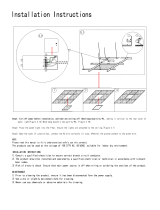
nstalling10hanging screwbolts.(4bolts)
O
O
Please refer to
the following figures for positioning 4 screw bolts.
Evaluate the ceiling construction and please install with 10
hanging screw bolts.
Consult the construction personnel for the specific procedures.
- Do keep the ceiling flat. Consolidate the roof beam to avoid
possible vibration.
Carry out the pipe and line operation in the ceiling after finishing
the installation of the main body. While choosing where to start
the operation, determine the direction of the pipes to be drawn
out. Especially in case there is a ceiling, position the refrigerant
pipes, drain pipes,indoor & outdoor lines to the connection
places before hanging up the machine.
The installation of hanging screw bolts.
- Cut off the roof beam.
- Streng then the place that has been cut off, and consolidate the
roof beam.
After the selection of installation location, position the refrigerant
pipes, drain pipes,indoor & outdoor wires to the connection
places before hanging up the machine.
The installation of hanging screw bolts.
Put the square
timber crosswise over the roo fbeam, then install the hanging
screw bolts.
Inlaying or embedding the screw bolts.
Use embedding screw bold, crock and stick harness.
Timber over
the beam
Roof beam
Ceiling
Hanging screw bolts
(Blade shape insertion)
(Slide
insertion)
Steel bar
Embedding screw bolt
(Pipe hanging and embedding screw bolt)
All the pictures in this manual are for explanation purpose only.
There may be slightly different from the air conditioner you
purchased ( depend on model ). The actual shape shall prevail.
NOTE
INSTALLATION MANUAL
7

1.2.4 Steel roof
beam structure
Install and use
directly the supporting angle steel.
Hanging screw bolt
Supporting
angle
steel
Hanging bolts
2 Overhangingthe indoor unit
(1) Overhang the indoor unit onto the hanging screw bolts with block.
(2) Position the indoor unit in a flat level by using the level indicator,
unless it may cause leakage.
Screw nut
Shockproof cushion
Shockproof cushion
Hanging
screw bolt
Washer
1.3 Duct and accessories installation
1. Install the filter(optional) according to air inlet size.
2. Install the canvas tie-in between the body and duct.
3. Air inlet and air outlet duct should be apart far enough to avoid air passage
short-circuit.
4. Recommended duct connection.
5.Please refer to the static pressure to install
Canvas tie-in
Canvas tie-in
Isolation
booth
Air inlet
Air dust filter
Checking
orifice
Isolation booth
Air outlet
1. Do not put the connecting duct weight on the indoor unit.
2. When connecting duct, use inflammable canvas tie-in to
prevent vibrating.
3. Insulation foam should be wrapped outside the duct to
avoid condensate an internal duct under layer shall be
added to reduce the noise for special requirement.
NOTE
INSTALLATION MANUAL
8

The positioning of
ceiling hole, indoor unit and hanging screw bolts
Unit: mm
INSTALLATION MANUAL
9
122
194
194
272
272
254
390
1138
Gas side liquid side
outlet
Pendant bolt hole
4-12x25
526
1372
1355
1246
704
760
795
Air outlet duct connection screw hole location diagram
Return air duct rivet screw hole location diagram
All the figures
in this manual are for explanation purpose only. They may be slightly different from the air
conditioner you purchased.The actual unit shall prevail.
NOTE

INSTALLATION MANUAL
10
Fan
performances
Static pressure curve
3500 3750 4000 4250 4500 4750 5000
0
25
50
75
air flow (m
3
/h)
Static pressure(Pa)
01
0
1
High air
Medium air
Low air
Static curve (ENC2) 0
0
0
8
4
1
2
3
5
6
7
C
9
A
B
D
E
F
0
8
4
1
2
3
5
6
7
C
9
A
B
D
E
F
0
8
4
1
2
3
5
6
7
C
9
A
B
D
E
F
0
8
4
1
2
3
5
6
7
C
9
A
B
D
E
F
ENC2
0
1
2
3
High static pressure
High static pressure
Code
0~50
51~80
81~120
121~150
Factory Setting
Factory Setting
For Setting Static pressure
For Setting Static pressure
3200 3400 3600 3800 4000 4200 4400 4600 4800
0
20
40
60
80
100
air flow (m
3
/h)
Static pressure(Pa)
01
0
1
High air
Medium air
Low air
Static curve (ENC2) 1
3000 3500 4000 4500 5000 5500 6000
0
25
50
75
100
125
150
air flow (m
3
/h)
Static pressure(Pa)
01
0
High air
Medium air
Low air
Static curve (ENC2) 2
3000 3500 4000 4500 5000 5500
0
50
100
150
200
01
0
High air
Medium air
Low air
Static curve (ENC2) 3
air flow (m
3
/h)
Static pressure(Pa)

2.1
Precautions for selectingthe location
2.2 Figure of body size
2.
OUTDOOR UNIT INSTALLATION
1)
Choose a place solid enough to bear the weight and vibration of
the unit, where the operation noise will not be amplified.
2) Choose a location where the hot air discharged from the unit or
the operation noise will not cause a nuisance to the neighbours
of the user.
3) Avoid places near a bedroom and the like, so that the operation
noise will cause no trouble.
4) There must be sufficient spaces for carrying the unit into and out
of the site.
5) There must be sufficient space for air passage and no
obstructions around the air inlet and the air outlet.
6) The site must be free from the possibility of flammable gas
leakage in a nearby place.
7) Install units, power cords and inter-unit wire at least 3m away from
television and radio sets. This is to prevent interference to images
and sounds. (Noises may be heard even if they are more than 3m
away depending on radio wave conditions.)
8) In coastal areas or other places with salty atmosphere of sulfate
gas, corrosion may shorten the life of the air conditioner.
9) Since drain flows out of the outdoor unit, do not place under the
unit anything which must be kept away from moisture.
Cannot be installed hanging from ceiling or stacked.NOTE:
When
operating the air conditioner in a low outdoor ambient
temperature, be sure to follow the instructions described below.
- To prevent exposure to wind, install the outdoor unit with its suction
side facing the wall.
- Never install the outdoor unit at a site where the suction side may
be exposed directly to wind.
- To prevent exposure to wind, it is recommended to install a baffle
plate on the air discharge side of the outdoor unit.
- In heavy snowfall areas, select an installation site where the snow
will not affect the unit.
CAUTION
- Construct a large canopy.
- Construct a pedestal.
Install
the unit high
enough off the
ground to prevent burying in snow.
INSTALLATION MANUAL
11
1558
1120
668 206
440
400
528
494

2.3 Installation guidelines
2.4 Outdoor unit installation
When
installing the outdoor unit, refer to "Precautions for
selecting the location" .
Check the strength and level of the installation ground so that
the unit will not cause any operating vibration or noise after
installed.
Fix the unit securely by means of the foundation bolts.
(Prepare 4 sets of M8 or M10 foundation bolts, nuts and
washers each which are available on the market.)
Where a wall or other obstacle is in the path of outdoor unit
inlet or outlet airflow, follow the installation guidelines below.
For any of the below installation patterns, the wall height on the
outlet side should be 1200mm or less.
's
1) Installingoutdoor unit
2) Drain work
If drain work is necessary, follow the procedures below.
'
Use drain plug for drainage.
If the drain port is covered by a mounting base or floor surface,
place additional foot bases of at least 30mm in height under the
outdoor unit s feet.
In cold areas, do not use a drain hose with the outdoor unit.
(Otherwise, drain water may freeze, impairing heating
performance.)
Drain
port
Bottom
frame
Seal
Drain plug
Hose
W
all facing one side
Walls facing three sides
Walls facing two sides
1200
or
less
Direction
of
air
More
than 100
More than 350
Side view
Top view
More than 50
More
than 100
More
than 350
More than 50
Top view
More
than
50
More
than
100
More
than 350
Unit:mm
Fix
with
bolts
INSTALLATION MANUAL
12

3. INSTALL THEREFRIGERANT PIPE
Execute
heat insulation work completely on both sides of the
gas piping and liquid piping. Otherwise, this can sometimes
result in water leakage.
(When using a heat pump, the temperature of the gas piping can
reach up to approximately 120 . Use insulation which is
sufficiently resistant.)
Before
rigging tubes, check which type of refrigerant is used.
All
field piping must be provided by a licensed refrigeration
technician and must comply with the relevant local and
national codes.
Use
a pipe cutter and flare suitable for used refrigerant.
Do not mix anything other than the specified refrigerant, such
as air, etc.., Inside the refrigerant circuit.
Coat the flare both inside and outside with ether oil or ester oil.
If the refrigerant gas leaks during the work, ventilate the area.
A toxic gas is emitted by the refrigerant gas being exposed to
a fire.
Make sure there is no refrigerant gas leak. A toxic gas may be
released by the refrigerant gas leaking indoor and being
exposed to flames from an area heater, cooking stove, etc.
Also,
in cases where the temperature and humidity of the
refrigerant piping sections might exceed 30 or Rh80%,
reinforce the refrigerant insulation(20mm or thicker).
Condensation may form on the surface of the insulating material.
Only
use annealed material for flare connections.
Coat
here with ether oil or ester oil
Precautions
3.1 Flaringthe pipe end
1)
Cut
the pipe end with a pipe cutter.
2) Remove burrs with the cut surface facing downward so that the
chips do not enter the pipe.
5) Check that the flaring is properly made.
Refer
to the table below for the dimensions of flare nuts spaces
and the appropriate tightening torque. (Over tightening may
damage the flare and cause leaks.)
Pipe
gauge
(mm)
Outer diam.
(mm)
Tightening torque
A(mm)
Max.
1.3
1.6
1.8
2.2
Min.
0.7
1.0
1.0
2.0
Flare dimension
A (mm)
Flare shape
O6.35
O6.35
15~16 N. m
(153~163 kgf.cm)
8.3~8.7
12.0~12.4
15.4~15.8
18.6~19.0
22.9~23.3
25~26 N. m
(255~265 kgf.cm)
35~36 N. m
(357~367 kgf.cm)
45~47 N. m
(459~480 kgf.cm)
97.2~118.6 N. m
(990~1210 kgf.cm)
O9.52
O9.52
O12.7
O12.7
O15.9
O19.1
O15.9
R0.4~0.8
45
2
90
4
A
o
o
1
Torque wrench
2 Flare nut
3 Piping union
4 Spanner
12
3
4
Align
the centres of both flares and tighten the flare nuts 3 or 4
turns by hand. Then tighten them fully with the torque wrenches.
3.2
Refrigerantpiping
Check
whether
the
height
drop
between the indoor unit and
outdoor unit, and the length of refrigerant pipe meet the following
requirements:
Cut
exactly at
right angles.
Remove burrs.
Flare
s inner surface
must be flaw-free
'
The pipe end must
be evenly flared in a
perfect circle.
Make sure that the
flare nut is fitted.
3)
Put the flare nut on the pipe.
4) Flare the pipe.
Die
Copper
pipe
A
Set exactly at the position shown below.
INSTALLATION MANUAL
13
25m
50m
30m
Max. actual length of pipe (L)
Allowed
value
Height difference
between indoor
unit and outdoor
unit (H)
Outdoor
(upper)
Outdoor
(lower)
Max. height
difference
Model Gas side Liquid side
MUCHR-96-H7T
φ
25.4mm
φ
9.5mm

3.3
Purging air and checkinggas leakage
When
piping work is completed, it is necessary to purge the
air and check for gas leakage.
W
ARNING
Do
not mix any substance other than the specified refrigerant
into the refrigeration cycle.
When refrigerant gas leaks occur, ventilate the room as soon as
possible.
The specified refrigerant should always be recovered and never
be released directly into the environment.
Use a vacuum pump for the specified refrigerant. Using the
same vacuum pump for different refrigerants may damage the
vacuum pump or the unit.
If
using additional refrigerant, perform air purging from the
refrigerant pipes and indoor unit using a vacuum pump, than
charge additional refrigerant.
Use a hexagonal wrench(4mm) to operate the stop valve rod.
All refrigerant pipe joints should be tightened with a torque
wrench at the specified tightening torque.
1) Connect projection side of charging hose (which comes from
gauge manifold) to gas stop valve's service port.
2) Full open gauge manifold's low-pressure valve (Lo) and
completely close its high-pressure valve (Hi)
(High-pressure valve subsequently requires no operation.)
3) Do vacuum pumping and make sure that the compound
pressure gauge reads -0.1MPa (-76cmHg).*1
4) Close gauge manifold's low-pressure valve (Lo) and sop
vacuum pump.
(Keep this state for a few minutes to make sure that the
compound pressure gauge pointer does not swing back.)*2
5) Remove caps from liquid stop valve and gas stop valve.
6) Turn the liquid stop valve's rod 90 degrees counterclockwise
with a hexagonal wrench to open valve.
Close it after 5 seconds, and check for gas leakage.
Using soapy water, check for gas leakage from indoor unit's
flare and outdoor unit's flare and valve rods.
After the check is complete, wipe all soapy water off.
7) Disconnect charging hose from gas stop valve's service port
then fully open liquid and gas stop valves.
(Do not attempt to turn valve rod beyond its stop.)
8) Tighten valve caps and service port caps for the liquid and
gas stop valves with a torque wrench at the specified torques.
*1. Pipe length vs. Vacuum pump run time
3.5 Refrigerantpiping work
Pipe
length and refrigerant amount:
Connective
pipe
length
3.4
Additional refrigerantcharge
CAUTION
Refrigerant
may only be charged after performing the leak
test and the vacuum pumping.
Check the type of refrigerant to be used on the machine
nameplate. Charging with an unsuitable refrigerant may
cause explosions and accidents, so always ensure that the
appropriate refrigerant is charged.
Refrigerant containers shall be opened slowly.
The outdoor unit is factory charged with refrigerant. Calculate the
added refrigerant according to the diameter and the length of the
liquid pipe of the outdoor unit/indoor unit connection.
1) Caution on the pipe handling
Protect the open end of the pipe against dust and moisture.
All pipe bends should be as gentle as possible. Use a pipe
bender for bending.
Be
sure to add the proper amount of additional refrigerant.
Failure to do so may result in reduced performance.
Pipe
length Up to 15m More than 15m
Not less than 15minNot less than 10 minRun time
*2. If the compound pressure gauge pointer swings back,
refrigerant may have water content or a loose pipe joint may
exist. Check all pipe joints and retighten nuts as needed,
then repeat steps 2) through 4).
Be sure to
place a cap.
If no flare cap is
available, cover the
flare mouth with
tape to keep dirt or
water out.
Wa
ll
Rain
Less
than
5m
More
than 5m
Air
purging
method
Use
vacuum
pump.
Use vacuum
pump.
Additional
amount
of
refrigerant
to be charged
R410A:(L-5)x30g/m
Liquid side:
INSTALLATION MANUAL
9.52mm (3/8")
14

For
local insulation, be sure to insulate local piping
all the way into the pipe connections inside the unit.
Exposed piping may cause condensation or may
cause burns when touched.
Make sure that no oil remains on plastic parts of the
decoration panel (optional equipment).
Oil may cause degradation and damage to plastic
parts.
1
Piping insulation material(field supply)
2 Flare nut connection
3 Insulation for fitting (field supply)
4 Piping insulation material (main unit)
5 Indoor unit
6 Clamp (field supply)
A Turn seams up
B Attach to base
C Tighten the part other than the piping insulation material
Piping
insulation procedure
Gas
piping Liquid
piping
1
1
6
6
6
6
4
4
5
5
3
3
2
2
A
A
C
C
B
B
2)
Besure to insulate both the gas and liquid piping. Use
separate thermal insulation pipes for gas and liquid
refrigerantpipes. See the figure below.
Inter-unit wire
Liquid pipe
Liquid pipe
insulation
Drain hose
Finishing tape
Gas pipe
insulation
Gas pipe
-
K
eep
piping
as short as possible and slope it downwards at a
gradient of at least 1/100 so that air may not remain trapped
inside the pipe.
- Keep pipe size equal to or greater than that of the connecting
pipe (PVC pipe, nominal diameter 20mm in, outside diameter
25mm).
- Push the drain hose as far as possible over the drain socket,
and tighten the metal clamp securely.
1-1.5m
Lean
over 1/50
4. CONNECT THE DRAIN PIPE
-
If the drain hose cannot be sufficiently set on a slope, fit the
hose with drain raising piping (field supply).
- Insulate the drain hose inside the building.
4.2 How to perform piping
1 Drain socket (attached to the unit)
2 metal clamp
3 Drain hose
4 Insulation (field supply)
- Make sure that heat insulation work is executed on the
following 2 spots to prevent any possible water leakage due
to dew condensation.
1 Indoor drain pipe.
2 Drain socket.
12
34
4.1
Install the drain pipes.
Thedrainpipeinstallationfortheunit
INSTALLATION MANUAL
15

5.
ELECTRIC WIRINGWORK
General instructions
All
field wiring and components must be installed by a licensed
electrician and must comply with relevant European and national
regulations.
Use copper wire only.
A circuit breaker capable of shutting down power supply to the
entire system must be installed.
Note that the operation will restart automatically if the main
power supply is turned off and then turned back on again.
Be sure to ground the air conditioner.
Do not connect the ground wire to gas pipes, water pipes,
lightning rods, or telephone ground wires.
- Gas pipes: might cause explosions or fire if gas leaks.
-.
-T
.
Water pipes: no grounding effect if hard vinyl piping is used
elephone ground wires or lightning rods: might cause
abnormally high electric potential in the ground during
lightning storms
Follow the 'Wiring diagram' attached to the unit body to wire the
outdoor unit, indoor units and the remote controller.
The
specification of power
INSTALLATION MANUAL
16
Indoor unit Outdoor unit
220-240V~ 50Hz
380-415V 3N~ 50Hz
Power
Switch capacity of the main
power suppliy/fuse(A)
Indoor unit power cable(mm
2
)
includes grounded wire
Outdoor unit power cable(mm
2
)
includes grounded wire
3×2.5 mm
2
5×6.0 mm
2
Indoor Unit /Outdoor
Unit Signal Wire (mm
2
)
(Weak electric signal)
3-core shielded wire
3X0.75
16A
40A
Connecting wiring
Outdoor unit
Signal wire between indoor/outdoor unit
Indoor unit
1
/ / /
34(
/
1(43 (<;
<(;
Branch Box
Please use 3-core shielded wire, and
connect the shielded layer to Grounding
Power Supply
Power Supply
;<(
Outdoor
Unit
Indoor
Unit
Power wiring
(indoor)
Communication Bus
wire distribution box
Switch / Circuit breaker
Switch / Circuit breaker
Power wiring
(outdoor)
Central control
monitor (CCM)
Computer
in broken line table, users can purchase the Central
control montior when necessary.please contract
with local supplier in details .
Power
(380-415V~ 50Hz 3-Phase)
Power
(220-240V~ 50Hz 1-Phase)
CCM
(Centralized controller)
Fig 1
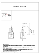
NOTE: The centralized CCM control must be connected to the XYE terminals of the indoor unit, and each indoor unit
connected to a CCM must have a different address, the addressing is done by the wired remote control KJR-29B.
IMPORTANT: Previously a bridge must be made in J2 (see Fig 1)

INSTALLATION MANUAL
17
PRECAUTIONS ON REFRIGERANT LEAKAGE
6.
b. Leak alarm related to mechanical ventilator
A. V
entilation
peristome
(Leak hunting siren should be installed in
places easily keep refrigerant)
Indoor unit
Outdoor unit
Indoor unit
Room full of leak refrigerant
(All refrigerant has run up)
Please press “constraint cool” button to carry out refrigerant
recycling process. Keep the low pressure above 0.2MPa, other
wise compressor may be burnt out.
Fig. 7-1
NOTE
This air conditioner(A/C) adopts inncouous and nonflammable
refrigerant. The locating room of the A/C should big engough
that any refrigerant leakage is unable to reach critical thickness.
So certain esssential action can be taken on time.
A[kg]
B[m ]
3
Critical thickness------the Max. thickness of Freon without any
harm to person.
3
Confirm the critical thickness through follow steps, and take
necessary actions.
1. Calculate the sum of the charge volume (A[kg])
Total
Refrigerant volume of 10HP=factory refrigerant
volume + superaddition
2. Calculate the indoor cubage (B[m ]) (as the minimum
cubage.
3
3. Calculate the refrigerant thickness
İ
İ
critical thickness
Counter measure against over high thickness
2. Install leak alarm facility related to mechanical ventilator if
you can not regularly ventilate.
Refrigerant critical thickness: 0.
30
[kg/m ] for R410A.
3
]
˖0.
3 [kg/m
1. Install
mechanical
under critical level. (ventilate regularly)
The owner's manual of indoor unit and owner's manual of
outdoor or unit must be turned over to the customer. Explain
the contents in the owner
’s manual to the customers in details.
6.1 Important information for the used
refrigerant
This product has the fluorinated gas, it is forbidden to release to air.
Refrigerant type: R410A; Volume of GWP: 2088;
GWP=Global Warming Potential
Attention:
Frequency of Refrigerant Leak Checks
1) For equipment that contains fluorinated greenhouse gases in
quantities of 5 tonnes of CO
2
equivalent or more,but of less than
50 tonnes of CO
2
equipment,at least every 12 months, or where
a leakage detection system is installed, at least every 24 months.
2) For equipment that contains fluorinated greenhouse gases in
quantities of 50 tonnes of CO
2
equivalent or more,but of less than
500 tonnes of CO
2
equipment,at least every six months, or where
a leakage detection system is installed, at least every 12 months.
3) For equipment that contains fluorinated greenhouse gases in
quantities of 500 tonnes of CO
2
equivalent or more,at least every
three months, or where a leakage detection system is installed,
at least every six months.
4) Non-hermetically sealed equipment charged with fluorinated
greenhouse gases shall only be sold to the end user where evidence
is provide that the installation is to be carried out by an undertaking
certified person.
5) Only certificated person is allowed to do installation, operation
and maintenance.
Model
Refrigerant/kg tonnes CO
2
equivalent
15.03
28kW
Factory charge
TURN OER TO THE CUSTOMER
7.
7.2

OWNER´S MANUAL
18
INVERTER SPLIT-TYPE
ROOM AIR CONDITIONER
The design and specifications are subject to
change without prior notice for product improvement.
Read This Manual:
Inside you will find many helpful hints on how to use and
maintain your air conditioner properly.
Just a little preventative care on your part can save you
a great deal of time and money over the life of your air
conditioner.
You'll find manyanswers to common problems in the
chart of troubleshooting tips. If you review the chart of
Troubleshooting Tips first, you may not need to call for
service.
Please read this manual carefully before installing
and using the unit.

INDOOR UNIT
OUTDOOR UNIT
Wire controller
Air filter (on some models)
Air inlet (side and rear)
Air outlet
Fig.1
1
2
3
4
5
6
7
Electric control cabinet
1
2
3
4
5
6
7
8
9
10
Connecting pipe
Air inlet
Drain pipe
Air outlet
Air inlet
INDOOR UNIT
OUTDOOR UNIT
0
NOTE
All the pictures in this manual are for explanation purpose only. They may be slightly different from the air conditioner
you purchased(depend on model).The actual shape shall prevail.
8
9
10
19
OWNER'S MANUAL

1. IMPORTANT SAFETY INFORMATION
To p
revent injury to the user or other people and property
damage, the following instructions must be followed. Incorrect
operation due to ignoring of instructions may cause harm or
damage.
Ask your dealer for installation of the air conditioner.
Incomplete installation performed by yourself may result in a
water leakage, electric shock, and fire.
Ask your dealer for improvement, repair, and
maintenance.
Incomplete improvement, repair, and maintenance may result
in a water leakage, electric shock, and fire.
In order to avoid electric shock, fire or injury, or if you
detect any abnormality such as smell of fire, turn off the
power supply and call your dealer for instructions.
Never let the indoor unit or the remote controller get wet.
It may cause an electric shock or a fire.
Never press the button of the remote controller with a
hard, pointed object.
The remote controller may be damaged.
Never replace a fuse with that of wrong rated current or
other wires when a fuse blows out.
Use of wire or copper wire may cause the unit to break down
or cause a fire.
Do not use the air conditioner for other purposes.
In order to avoid any quality deterioration, do not use the unit
for cooling precision instruments, food, plants, animals or
works of art.
Before cleaning, be sure to stop the operation, turn the
breaker off or pull out the supply cord.
Otherwise, an electric shock and injury may result.
In order to avoid electric shock or fire, make sure that an
earth leak detector is installed.
Be sure the air conditioner is grounded.
In order to avoid electric shock, make sure that the unit is
grounded and that the earth wire is not connected to gas or
water pipe, lightning conductor or telephone earth wire.
It is not good for your health to expose your body to the
air flow for a long time.
Do not insert fingers, rods or other objects into the air
inlet or outlet.
When the fan is rotating at high speed, it will cause injury.
Never use a flammable spray such as hair spray,lacquer
or paint near the unit.
It may cause a fire.
Never touch the air outlet or the horizontal blades while
the swing flap is in operation.
Fingers may become caught or the unit may break down.
Never put any objects into the air inlet or outlet.
Objects touching the fan at high speed can be dangerous.
Never inspect or service the unit by yourself.
Ask a qualified service person to perform this work.
Do not dispose this product as unsorted municipal
waste.Collection of such waste separately for special
treatment is necessary.
Do not dispose of electrical appliances as unsorted municipal
waste, use separate collection facilities.
Contact you local government for information regarding the
connection systems available.
If electrical appliances are disposed of in landfills or
dumps, hazardous substances can leak into the
groundeater and get into the food chain, damaging your
health and well-being
To prevent refrigerant leak, contact your dealer.
When the system is installed and runs in a small room, it is
required to keep the concentration of the refrigerant, if by any
chance coming out, below the limit. Otherwise, oxygen in the
room may be affected, resulting in a serious accident.
The refrigerant in the air conditioner is safe and normally
does not leak.
If the refrigerant leaks in the room, contact with a fire of a
burner, a heater or a cooker may result in a harmful gas.
Turn off any combustible heating devices, ventilate the
room, and contact the dealer where you purchased the
unit.
Do not use the air conditioner until a service person confirms
that the portion where the refrigerant leaks is repaired.
The safty precautions listed here are divided into two categories. In
either case, important safty information is listed which must be read
carefull y .
Fai
lure to observe a caution may result in injury or damage
to the equipment.
in death.
The appliance shall be installed in accordance with national
wiring regulations.Failure to observe a warning may result
CONTENTS PAGE
IMPORTANT SAFETY INFORMATION.......................................................9
PARTS NAMES........................................................................................
AIR CONDITIONER OPERATIONS AND PERFORMANCE...........................
HINTS FOR ECONOMICAL OPERA
TION
....................................................
MAINTENANCE
.......................................................................................
FOLLOWING SYMPTOMS ARE NOT AIR CONDITIONER TROUBLES........
TROUBLESHOOTING...............................................................................
CAUTION
CAUTION
WARNING
WARNING
20
20
21
22
22
22
24
25
OWNER'S MANUAL
/