Page is loading ...

OPERATION AND
MAINTENANCE MANUAL
Gas-fired Steam Humidifier
Nortec GS
Series II
2596646_B_EN_2010_Nortec-GS_OM
Humidication and Evaporative Cooling
NORTEC

Thank you for choosing Condair
Installation date (DD/MM/YYYY):
Commissioning date (DD/MM/YYYY):
Site:
Model:
Serial number:
Proprietary Notice
This document and the information disclosed herein are proprietary data of Condair Ltd. Neither this document, nor
the information contained herein shall be reproduced, used, or disclosed to others without the written authorization of
Condair Ltd., except to the extent required for installation, operation or maintenance of the customer's equipment.
Liability Notice
Condair Ltd. does not accept any liability due to incorrect installation, maintenance or operation of the equipment,
or due to the use of parts/components/equipment that are not authorized by Condair Ltd..
Copyright Notice
© Condair Ltd., All rights reserved.
Technical modications reserved.

3
Contents
Nortec GS
2596646_B_EN_2010_Nortec-GS_OM
Contents
1 Introduction 5
1.1 Notes on this manual 5
2 For Your Safety 6
3 Product Overview 10
3.1 General Description 10
3.2 Functional Description 12
4 Operator Interface 14
4.1 Controls 14
4.2 Control Software 14
4.2.1 Home Screen 14
4.2.2 Operating Status 15
4.2.3 Maintenance and Fault Status 16
4.2.4 Help 16
4.2.5 System Information 16
4.2.6 Main Menu 20
4.2.6.1 Conguration Menu 20
4.2.6.2 Service Menu 34
4.2.6.3 Setpoint 36
4.2.6.4 Administrator Menu 36
4.3 Software Conguration 38
4.3.1 Conguring the Control Software 38
4.3.2 Conguring for Multi-Unit Operation 38
5 Operation 40
5.1 General 40
5.2 Operating Procedures 40
5.2.1 Filling the System 40
5.2.2 Ignition Safety Shuto Test 40
5.2.3 Starting the Humidier 41
5.2.4 Remote Monitoring 42
5.2.5 Inspections During Operation 42
5.2.6 Manually Initiate Tank Draining 43
5.2.7 Full Tank Blowdown 43
5.2.8 Shutting Down 44
5.2.9 Restarting After Shutdown 44
6 Maintenance 45
6.1 General 45
6.2 Mandatory Maintenance Schedule 46
6.3 List of Consumables 47
6.4 Management of Scale and Chloride Levels 47
6.4.1 Adjusting Blowdown Settings 48
6.5 Maintenance Procedures 49
6.5.1 Removal and Installation of Access Panels 49
6.5.2 Cleaning the Tank 50

4
Contents
Nortec GS
2596646_B_EN_2010_Nortec-GS_OM
6.5.3 Cleaning the Secondary Heat-exchanger 51
6.5.4 Cleaning the Float Chamber 52
6.5.5 Cleaning Hoses, Dual Fill Valves and Drain Pump 53
6.5.6 Cleaning the Burner Assembly 55
6.5.7 Replacing Backup Battery 56
6.5.8 Replacing Internal Fuse 57
6.5.9 Resetting Service Reminder 57
6.5.10 Installing Software Updates 57
7 Fault Isolation 58
7.1 General 58
7.2 Fault Indication 58
7.3 General Troubleshooting 58
7.4 Warning and Fault List 59
7.5 Resetting Fault Status 66
8 Decommissioning 67
8.1 General 67
8.2 Removal from Service for Disposal or Long-term Storage 67
8.3 Disposal/Recycling 67
9 Performance and Operating Data 68
9.1 Performance Data 68
9.2 Operating Data 68

5
IntroductionNortec GS
2596646_B_EN_2010_Nortec-GS_OM
1 Introduction
Thank you for purchasing the Nortec GS steam humidier.
The Nortec GS steam humidier incorporates the latest technical advances and meets all recognized
safety standards. Improper use of the Nortec GS humidier may result in danger to the user or third
parties, and/or damage to property.
To ensure a safe, proper, and economical operation of the Nortec GS steam humidier, observe and
comply with all information and safety instructions contained in this manual, as well as all relevant
documentation of components of the installed humidication system. Comply with all local and regional
regulations dealing with gas, combustion air, ue gases, water, steam and electrical systems.
If you have additional questions, contact your Condair representative. They will be glad to assist you.
1.1 Notes on this manual
Limitation
The subject of this manual is the Nortec GS steam humidier in its dierent versions. The various options
and accessories may only be described in-so-far as is necessary for proper installation and operation of the
equipment. Additional information on available options and accessories can be obtained in the instructions
that are supplied with them.
This manual is restricted to the operation and maintenance of the Nortec GS steam humidier, and is
intended for well trained personnel who are suitably qualied for their respective tasks.
Other Related Publications
This manual is supplemented by other publications such as the Installation Manual , Spare Parts List,
etc., which are included in the delivery of the equipment. Where necessary, appropriate cross-references
to these publications have been added in this manual.
Storage of Manual
Keep this manual in a place where it is safe and readily accessible. If the equipment is moved to another
location, make sure that the manual is passed on to the new user. If the manual is lost or misplaced,
contact your Condair representative for a replacement copy.
Language Versions
This manual is also available in other languages – contact your Condair representative.

6
For Your Safety Nortec GS 2596646_B_EN_2010_Nortec-GS_OM
2 For Your Safety
General
Every person who is tasked with the operation and maintenance of the Nortec GS humidier must read
and understand this manual before performing any work on the unit. Knowing and understanding the
contents of the Installation Manual, and the Operation and Maintenance Manual is a basic requirement
for protecting personnel against any kind of danger, preventing faulty operation, and operating the unit
safely and correctly.
All labels, signs and markings applied to the Nortec GS humidier must be observed and kept in a
readable state.
Personnel Qualications
All procedures described in this manual must only be performed by personnel who are adequately
qualied, well trained and are authorized by the customer.
For safety and warranty reasons, any activity beyond the scope of this manual must only be performed
by qualied personnel authorized by Condair.
All personnel working with the Nortec GS humidier must be familiar with, and comply with the appropriate
regulations on workplace safety and prevention of accidents.
Intended Use
The humidier is intended exclusively for air humidication using a Condair-approved steam distributor
within specied operating conditions (refer to "Operating Data" on page 68 for details). Any other type of
application, without the express written consent of Condair, is considered to be NOT conforming to its
intended purpose, and may lead to dangerous operation and will void the warranty.
In order to operate the equipment in the intended manner all information contained in this manual, in
particular the safety instructions, must be observed closely.
Safety Precautions that Must be Observed
DANGER!
Risk of electric shock!
The Nortec GS humidier is mains powered. Live parts may be exposed when the access
panels are removed. Touching live parts may cause severe injury or even death.
Prevention: Before performing any work inside the Nortec GS humidier shut down the humidier
properly and secure it against accidental power-up as described in "Shutting Down" on page 44.
WARNING!
Wiring errors can cause improper and dangerous operation of the humidier!
Prevention: Tag all wires before disconnecting them. Reconnect all wires correctly after servicing,
and check the unit functions properly.
CAUTION!
Electrostatic discharge (ESD)!
The electronic components inside the control cabinet in the humidier are sensitive to elec-
trostatic discharge (ESD).
Prevention: Take appropriate measures to protect the electronic components inside the unit against
damage caused by electrostatic discharge (ESD).

7
For Your SafetyNortec GS
2596646_B_EN_2010_Nortec-GS_OM
DANGER!
Risk of re or explosion!
The Nortec GS is a gas-red humidier. Improper installation, adjustment, alteration, service,
maintenance or use can cause carbon monoxide poisoning, explosion, re or other hazards
that can cause serious injury, death or property damage.
If over-heating occurs or if the gas fails to shut o: Shut o the gas supply at the manual gas
shuto valve before shutting o the electrical power supply.
DO NOT spray aerosols in the vicinity of this appliance while it is in operation.
DO NOT place articles on or against this appliance.
DO NOT use or store ammable materials in or near this appliance.
DO NOT use this appliance if any part has been under water. Call a qualied service techni-
cian immediately to inspect and replace any part of the control system or gas control that has been
under water.
Any work on the gas system must only be performed by a qualied installer, service agency or
your local gas supplier. Use only factory-authorized and listed kits or accessories when installing or
modifying this appliance.
DO NOT store or use gasoline or other ammable vapours and liquids in the vicinity of the humidi-
er or any other appliance.
What to do if You Smell Gas:
DO NOT try to light any appliance.
DO NOT touch any electrical switch.
DO NOT use any phone in the building.
Leave the building immediately.
Call your gas supplier immediately from a location far away from the building with the gas leak.
Follow the gas supplier's instructions.
If you cannot reach your gas supplier, call the re department.
WARNING!
Risk of severe burns from contact with hot surfaces, steam or hot water!
The tank may contain steam or hot water at up to 100 °C (212 °F). Contact with the hot sur-
faces, steam vapours or hot water can result in severe burns.
Prevention: Always drain the tank, and allow the unit to cool down to a safe temperature before
cleaning the tank. Never open the tank until it has been fully drained. Never use the manual drain
valve until the unit has cooled down. Use the manual drain valve to verify that the tank is empty
before removing the tank cover.
WARNING!
Risk of severe burns from contact with hot steam vapours!
The Nortec GS humidier produces hot steam vapours for humidication. Bare skin in contact with
hot steam vapours can result in severe burns.
Prevention: Never perform any work on the steam system (including the steam lines, steam dis-
tributors, etc.) while the humidier is operating. Shut down the Nortec GS steam humidier, as
described in "Shutting Down" on page 44 before xing any leaks in the steam system.

8
For Your Safety Nortec GS 2596646_B_EN_2010_Nortec-GS_OM
WARNING!
Risk of severe burns from contact with hot surfaces!
The water tank, steam line and exhaust system in the Nortec GS humidier get very hot during
operation. Bare skin in contact with hot surfaces can result in severe burns.
Prevention: Shut down the Nortec GS steam humidier as described in "Shutting Down" on page 44
and wait for the components to cool down before performing any work on the unit. Never use the
manual drain valve until the unit has cooled down. Use the manual drain valve to verify that the tank
is empty before removing the tank cover. Drain the tank as described in "Manually Initiate Tank Draining"
on page 43.
WARNING!
Risk of personal injury!
Prevention: Wear a safety mask and clean the burner assembly in a well ventilated area.
CAUTION!
Risk of damage to the humidier components!
Do not use solvents, aromatized or halogenized hydrocarbons, or other harsh chemicals for clean-
ing. Disinfectants may only be used if they do not leave behind toxic residue. Rinse all parts thor-
oughly with clean tap water after cleaning.
WARNING!
Risk of re!
DO NOT clean the sacricial anode with any chemicals. The anode can react with acids to
create ammable hydrogen gas.
CAUTION!
Risk of damage to the humidier components or injury!
DO NOT over-torque the bolts. Ensure the proper order of torquing is followed. Failure to do so
may cause damage to the humidifer components or injury.
DANGER!
Risk of harm to personnel or damage to property.
Operating a damaged or improperly secured humidier presents a risk of danger to person-
nel or damage to property.
Prevention: Do not restart a damaged or improperly secured humidier.
Preventing Unsafe Operation
All personnel working with the unit must immediately report to the customer any alterations to the unit
that may aect safety, and if it is suspected that the Condair GS steam humidier cannot be operated
safely for any of the reasons listed below, shut it down immediately as described in "Shutting Down" on
page 44 and secure it against accidental power-up.
• Humidier is damaged
• Electrical connections are loose or damaged
• Humidier is not operating properly
• Leaks in the steam system or gas supplyDO NOT modify this appliance.
Modications are NOT permitted on the Nortec GS humidier without the express written consent of
Condair.
Always use original Condair replacement parts and accessories available through your Condair
representative.

9
For Your SafetyNortec GS
2596646_B_EN_2010_Nortec-GS_OM
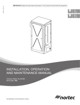
The location of the various safety labels on the Nortec GS humidier is shown below.
4
3
2
5
1
Figure 1: Safety Labels
1 Label, gas safety warning
2 Label, keep cabinet closed warning
3 Label, installation guidelines
4 Label, general safety warning
5 Label, specication

10
Product Overview Nortec GS 2596646_B_EN_2010_Nortec-GS_OM
3 Product Overview
3.1 General Description
The Nortec GS series is a completely new design of gas-red steam humidiers. It is designed to provide
clean steam humidication at an economical price. The Nortec GS humidier is available in condensing
high-eciency (CS), ultra-low NOx condensing (NX), and Mid-Temperature models in capacities ranging
from 50 lb/h to 600 lb/h (23 kg/h to 260 kg/h). The CS and NX models are installed as Category IV
appliances. The MT models are installed as Category III and Category IV appliances.
The humidier has an integrated control board that controls the humidier, and also allows the humidier
to be connected to a building automation system (BACnet, Lonworks, Modbus), or the internet so it can be
controlled and monitored remotely. In addition, up to four humidiers can be set up in a "Main-Extension"
conguration using Condair's Linkup system to satisfy large humidication needs.
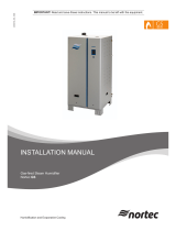
The Nortec GS humidier comes in two housing styles – compact 50-100 lb/h (23-45 kg/h), and full-size
150-600 lb/h (65-260 kg/h). Refer to Figure 2.
5
4
3
2
1
Figure 2: Nortec GS-Series II Humidiers
1 Nortec GS 50/100 (compact housing)
2 Nortec GS 150 (full-size housing)
3 Nortec GS 200/300 (full-size housing)
4 Nortec GS 450 (full-size housing)
5 Nortec GS 600 (full-size housing)
The table below lists the summary of major components in each GS model. Refer to Figure 3 on page 11.
Table 1: GS Components by Model
Component
Quantity
Nortec GS
50/100
Nortec GS
150
Nortec GS
200/300
Nortec GS
450
Nortec GS
600
Primary heat-exchanger 1 1 2 3 4
Secondary heat-exchanger 1* 1* 1* 2* 2*
Water tank 1 1 1 1 1
Burner 1 1 2 3 4
Blower 1 1 2 3 4
Gas valve 1 1 2 3 4
Ignition control module 1 1 2 3 4
Spark-igniter and ame sensor 1 1 2 3 4
Dual ll valve 1 1 1 2 2
* Secondary heat-exchanger on CS and NX models only.

11
Product OverviewNortec GS
2596646_B_EN_2010_Nortec-GS_OM
20
19
18
17
13
10
11
12
14
16
15
2
11
6
8
1
3
4
5
7
12
15
11
2
3
4
5
6
7
1
9
10
13
14
Figure 3: Humidier Components (GS 100 and 300 shown). Door, side and top panels removed for clarity.
1 Steam outlet
2 High limit sensor
3 Blower
4 Burner
5 Tank door
6 Gas inlet
7 Combustion air inlet
8 Exhaust Manifold (GS 200-600)
9 Float chamber
10 Overow
11 Condensate trap (from exhaust)
12 Secondary heat-exchanger (CS/NX)
13 Drain valve
14 Dual ll valve
15 Silicone tube, exhaust
16 Exhaust adapter
17 Low voltage terminal
18 Integrated control board
19 PCB board
20 High voltage terminal

12
Product Overview Nortec GS 2596646_B_EN_2010_Nortec-GS_OM
3.2 Functional Description
Combustion
The combustion system consists of a fully modulating forced-draft combustion air blower(s), a negative
pressure regulated gas valve(s), and a premix burner(s). On a call for humidity, the blower is energized
to purge the system. During this time the control software performs diagnostic checks of the safety
systems – the air proving switch (not shown), the over-temperature switch and the external vent, as
well as the blowers. If the air proving switch is open, the warning message "AP Open Warn" appears, and
escalates to the fault message "AP Open Fault" if three consecutive warnings occur. At the same time, if
the over-temperature switch is open, the fault message "Over-Temperature Fault" appears. In addition, if any
of the blowers fail to operate during this time, the fault message "Blower Not Operating" appears. When the
functions of the safety systems have been veried successfully, the gas valve(s) opens and the gas-
air mixture is pushed through the burner ports into the combustion chamber(s). The spark-igniter(s) is
simultaneously activated to ignite the gas-air mixture.
If a ame is not sensed by the ame sensor(s), the above sequence is repeated after 15 seconds. The
sequence is repeated up to a maximum of three times, after which the ignition control module(s) locks
out and the fault message "Ignition Fail" appears. If a ame is sensed by the ame sensor(s), the gas
valve(s) remains open and combustion continues. The gas valve(s) continues to maintain a constant
air-to-gas ratio independent of the blower speed or external conditions.
On the CS and NX models, the hot ue gases pass through the primary heat-exchanger then the secondary
heat-exchanger, where it is cooled further before it exits through the exhaust vent. The heat recovered
by the secondary heat-exchanger is used to warm up the feed water. On the standard-eciency model,
the hot ue gases pass through the primary heat-exchanger and exit through the exhaust vent.
Water Management
The humidier is equipped with a oat chamber that monitors the water level in the tank.
The tank is supplied with water from the water supply, and from the secondary heat exchanger in CS
and NX models. A vacuum break valve is used to prevent siphoning in the drain connection.
In the CS and NX model, a secondary heat-exchanger promotes higher ecencies. This is achieved by
using the heat from the exhaust to pre-heat the cold ll water entering the tank.
The oat chamber is connected to the top and bottom of the tank to monitor water levels with reference
to the low operational pressure inside the tank. The oat chamber and its control board consists of two
magnetic oats (one is a backup) that measure the water level. These levels correspond to 3 LEDs on
a display panel and are monitored by the control software.
Water Levels:
L5 (yellow LED) — high water level
L4 (green and yellow LED) —
intermediate water level
L3 (green LED) — middle water level
L2 (green and red LED) — intermediate
water level
L1 (red LED) — low water level
On initial start-up, the dual ll valves ll the tank and the oat chamber. A start-up test monitors the water
level as the tank and oat chamber lls, and ensures proper functioning of the unit.
Note: A fault message "Float Level" may appear at any time. This indicates an invalid combination of
readings from the control software (for example, if L5 and L1 LEDs activate at the same time).
1. The water level reaches the backup oat, then the main oat.
2. As water lls the oat chamber and reaches the L1 level, the control software performs a test to
verify proper functioning of the dual ll valves and the drain pump.
a. Water enters the oat chamber via the tank. The ll valves will allow water to ll the tank and
raise the water level in the oat chamber to L5.
b. The drain pump energizes to lower the water level to just below L3.

13
Product OverviewNortec GS
2596646_B_EN_2010_Nortec-GS_OM
Note: The water levels should appear in ascending then descending order; L1, L2, L3, L4, L5, L4,
L3. A fault message "Fill Check Fault" appears if the water level does not rise to level L5. A fault
message "Drain Check" appears if the water lvel does not drop below the level L3.
3. When the test is complete, the dual ll valves activate and the water level should rise to level L3.
4. If a demand signal is present, the humidier begins the combustion sequence.
5. The drain pump and dual ll valves maintain the water level between levels L2 and L5.
If Float Check is enabled during steam production, the control software will activate the drain sequence
every 24 hours (adjustable to any time of day) to verify proper functioning of the oats, dual ll valves,
and the drain pump.
Figure 4: General System Overview (full-size unit Nortec GS 150 shown)
1 Humidistat, On/Off (used for humidity
control)
2 Humidity sensor or modulating humidis-
tat (used for control of the space in the
return duct, high limit in the supply duct)
3 Duct, return air
4 Duct, supply air
5 Humidistat, On/Off, high limit (external
security loop)
6 Drain line, condensate (with trap)
7 Funnel, air gap (with optional trap)
8 Supply line, gas
9 Manual gas shutoff valve
10 Fitting, union
11 Trap, sediment
12 Filter, water (optional, but recommended)
13 Valve, water shutoff
14 Supply line, water
15 Fitting, union
16 Switch, disconnect, electrical fused
(dedicated)
17 Drain line
18 Drain line, exhaust condensate (CS/NX
model only)
19 Steam line
20 Vent, air intake (connected to exterior
– optional)
21 Vent, exhaust vent (connected to
exterior)
22 Distributor, steam
23 Switch, air proving (external security
loop)
24 Double check valve backow preventer
(supplied by others)

14
Operator Interface Nortec GS 2596646_B_EN_2010_Nortec-GS_OM
4 Operator Interface
4.1 Controls
The operator interface in the Nortec GS humidier is located on the front of the unit – refer to Figure 5. It
consists of a touchscreen display with a LED status indicator, and an On/O switch. Refer to Table 2 for
a description of each of these elements.
1
2
3
Figure 5: Operator Interface
1 Display, touchscreen 2 Status indicator, LED 3 Switch, On/Off
DANGER!
Risk of electric shock!
The control cabinet in the humidier has live voltage. Turning o the unit at the On/O
switch does not shut o power to the control cabinet, which still has live voltage. Touching
live parts may cause severe injury or even death.
Prevention: Shut down the humidier properly as described in "Shutting Down" on page 44 before ac-
cessing the control cabinet in the humidier.
Table 2: Operator Interface Element Functions
Element Description
Touchscreen display Allows the user to monitor or control the Nortec GS humidier. Refer to "Control Software" on page 14
for details of the software interface.
LED status indicator The status LED is a multi-function LED, which lights up in dierent colours depending on the operat-
ing status of the humidier.
Green: indicates that the Nortec GS humidier is operating normally and humidifying.
Flashing Green: indicates that the Nortec GS humidier is in standby mode.
Yellow: indicates that a warning condition is present, or the humidier is due for maintenance.
Red: indicates that a fault condition is present, and humidication is stopped.
On/O switch Allows the user to turn the Nortec GS humidier on or o.
4.2 Control Software
4.2.1 Home Screen
When the Nortec GS humidier is turned on, it starts initializing and performs system checks. When
initialization and system checks are completed successfully, it goes into the normal operating mode.
The Home screen then appears on the touchscreen display.
The major elements of the Home screen are shown in Figure 6.

15
Operator InterfaceNortec GS
2596646_B_EN_2010_Nortec-GS_OM
2
3
4
5
6
7
8
9
1
10
Figure 6: Home Screen Elements
1 Date and time, Current
2 Operating status message – refer to
"Operating Status" on page 15 for
details.
3 Humidity control information – shows
the type of control signal and the steam
output requested.
4 Service/Warning/Fault status message –
refer to "Maintenance and Fault Status"
on page 16 for details.
5 Button, <Help> – access technical sup-
port help information. Refer to "Help" on
page 16 for details.
6 Button, <Drain> – manually initiate the
drain function. Refer to "Manually Initiate
Tank Draining" on page 43 for details.
7 Button, <About> – access the system in-
formation. Refer to "System Information"
on page 16 for details.
8 Button, <Menu> – access the Main menu.
Refer to "Main Menu" on page 20
for details.
9 Visual indication, current steam output
level
10 Model number, humidier
4.2.2 Operating Status
The operating status area of the Home screen (refer to Table 3 on page 15) shows the current operating
status message and an associated status icon. The messages are described in Table 3, and the status
icons are described in Table 4.
Table 3: Operating Status Descriptions
Message Description
Humidifying The humidier is generating steam.
Stopped The humidier is stopped because a condition with a "Fault" status is active.
Disabled The Nortec GS humidier is disabled by the BMS (building management system).
Safety Loop One or more contacts in the external security loop is open, so the humidier has stopped producing steam.
Idle The humidier is in standby mode (no humidity demand). The humidier will remain in this state until it re-
ceives a valid humidity demand signal.
Idle Drain The humidier is in standby mode (no humidity demand) and will remain in this state until a demand signal is
received, or until the Idle Drain Time has elapsed (and the Idle Drain function is active). The humidier will drain
when Idle Drain Time has elapsed.
Idle Empty Indicates that the tank is empty during idle.
Keep Warm The humidier is in standby mode, and the Keep Warm function is activated.
Filling Indicates that the tank is being lled.
Fill check The humidier is performing a ll check.
Drain check The humidier is performing a drain check.
Draining The humidier is draining.

16
Operator Interface Nortec GS 2596646_B_EN_2010_Nortec-GS_OM
Table 4: Status Icon Descriptions
Icon Description
The icon appears to the left of the operating status message or the maintenance/fault message when
the system is working normally.
Warning
The icon appears to the left of the maintenance/fault status message when a maintenance reminder
or a condition with a "Warning" status is active. The humidier will continue to produce steam when
there is a demand (unless the warning relates to a control signal).
A condition with a "Warning" status is active. Typically, these conditions are of a temporary nature,
or conditions that cannot cause damage to the system. Depending on the condition, the Nortec GS
humidier may be stopped or remains operable (unless the warning relates to a control signal). If the
cause of the condition clears on its own accord, the warning message is automatically reset. If the
condition becomes worse, a fault message may be triggered.
When a warning message is active, the status LED turns yellow in color.
Fault
The icon shown appears to the left of the maintenance/fault status message when a condition with a
"Fault" status is active. The humidier stops producing steam.
A condition with a "Fault" status is active. Typically, these are conditions which prevent further opera-
tion of the humidier, or conditions that can cause damage to the system. When a fault condition
occurs, the Nortec GS humidier stops steam production immediately.
When a fault message is active, the status LED turns red in color.
4.2.3 Maintenance and Fault Status
The Service/Warning/Fault status area of the Home screen (refer to Table 5 on page 16) shows maintenance
reminders, warning and fault status messages along with associated status icons. This eld also allows
access to the "Service Menu". When a maintenance reminder, warning or fault status message is active,
the list of current faults/warnings can be accessed directly from this eld to view additional details.
The general maintenance reminders and alarm messages displayed in this area are described in Table 5,
and the status icons are described in Table 4. Refer to ""Warning and Fault List" on page 59 .
Table 5: Maintenance/Fault Status Descriptions
Message Description
Service info No faults conditions present.
Maint. Warning This maintenance reminder appears when the Service Interval time set in the control software
has elapsed. The unit can continue to operate for another 200 hours, after which a corre-
sponding fault message appears and the unit stops operating.
Perform the required scheduled maintenance, then reset the service reminder in the Service
menu. Refer to "Maintenance Procedures" on page 49.
Warning A condition with a "Warning" status is active. Depending on the warning condition, the hu-
midier will continue to produce steam when there is a demand (unless the warning relates
to a control signal).
In addition, the status LED turns yellow in colour.
Fault A condition with a "Fault" status is active. The humidier will not produce steam until the fault
condition is cleared.
In addition, the status LED turns red in colour.
4.2.4 Help
Touch the <Help> button on the Home screen (refer to Figure 6 on page 15) to view your local technical
support help details.
4.2.5 System Information
Select the <About> button on the Home screen (refer to Figure 6 on page 15) to view the system information
for your Nortec GS humidier. The tab structure for this selection is shown below.

17
Operator InterfaceNortec GS
2596646_B_EN_2010_Nortec-GS_OM
General Tab
– Serial Number: shows the serial number, which is also shown on
the specication label.
– Humidier Model: shows the model number, which is also shown
on the specication label (on the right side of the humidier).
– Humidier Capacity: shows the total steam output capacity of the
humidier.
– Software Version: shows the current version of the control soft-
ware. Select the eld to update the control software – refer to
"Software Settings Tab" on page 37 for details.
– Driver Board A/B Version: shows the current version of the driver
board.
– Graph: shows you a trend data.
– Export Trend Data: sends the data to a connected USB drive.
Timer Tab
– On/O Timers: allow you to enable or disable the On/O timer
function to permit disabling of steam production during specied
days and times.
Conguration >Features > Operation > On/O Timers
– Capacity Timers: allow you to enable or disable the timer func-
tion, and congure up to eight dierent events with dierent output
capacities. The event timers for the capacity set in
Conguration > Features > Operation > Capacity Timers

18
Operator Interface Nortec GS 2596646_B_EN_2010_Nortec-GS_OM
Operational Status Tab
– Output: shows the current actual steam output level of the
humidier.
– Operating Hours: shows the current accumulated number of hours
the humidier has been producing steam since startup.
– Weighted Hours: shows the number of operating hours on the unit
weighted x demand % output.
– Average Demand: shows the time-averaged demand on the
system.
– Service Hours: shows the service interval.
– Est(imated) Days to Service: shows the number of days before
the unit is due for service (based on average humidier demand).
Control Status Tab
– Demand: shows the calculated demand for the unit as a percent-
age of its maximum capacity.
– Linkup: shows the humidier's 'position' in the linkup chain. Select
to set the humidier
– Safety Loop: shows the current status of the On/O devices in the
safety loop. If the loop is open, the unit will not produce steam.
– Manual Capacity: shows the capacity limitation value as a per-
centage of the maximum capacity of the unit. Select the eld to set
a xed maximum output capacity.
– Channel 1: shows the input signal for Channel 1. If congured for
demand control, it represents the demand. If congured for RH(P/
PI), it represents sensed humidity.
– Setpoint Channel 1: shows the current xed humidity setpoint
value for the unit. Select the eld to adjust the setpoint value. Refer
to "PI Control Parameters Tab" on page 25 for more details.
Note:
This eld appears only if Control Mode is set to "RH P" or "RH PI".
– Channel 2: shows the input signal for Channel 2. If congured for
demand control, it represents the demand. If congured for RH(P/
PI), it represents sensed humidity.
Note: This eld appears only if the Control Channels is set to "Dual".
– Setpoint Channel 2: shows the high limit setpoint value for the
unit. Select the eld to adjust the value.
Note: This eld appears only if Control Mode is set to "RH P" or "RH
PI", and Control Channels is set to "Dual".

19
Operator InterfaceNortec GS
2596646_B_EN_2010_Nortec-GS_OM
Features Tab
– Blowdown Rate: shows the rate at which the tank is partially
drained, as a percentage of actual steam production. Refer to the
"Water Management Tab" on page 21 for more details.
– Drain Cool: shows the conguration setting of the drain cool func-
tion. Select the eld to choose a dierent mode – "O", "On" or
"Smart". Refer to the "Water Management Tab" on page 21 for more
details.
– Float Check: shows the conguration setting of the oat check
function. Select the eld to enable or disable the function. Refer to
the "Operation Tab" on page 23 for more details.
– Float Check Time: allows you to see and set the time of day when
the oat check function will occur.
– FTBD (Full Tank Blowdown): shows the conguration setting of
the full tank blowdown function. Select the eld to enable or disable
the function. Refer to the "Water Management Tab" on page 21 for more
details.
– FTBD Interval: shows how often a full tank blowdown will occur.
Refer to the "Water Management Tab" on page 21 for more details.
– FTBD Time: shows the time of day when a full tank blowdown
will occur. Refer to the "Water Management Tab" on page 21 for more
details.
– Time Proportioning: shows the conguration setting of the time
proportioning function. Select the eld to enable or disable the
function. Refer to the "Operation Tab" on page 23 for more details.
– Idle Mode: allows you to set the idle function of the humidier
when it is in standby mode.
– Idle Drain Time: allows you to set the time duration the humidier
stays in standby mode without a demand, after which the humidier
carries out the function specied in Idle Mode.
– Short Cycle: allows you to enable or disable a timer function that
delays steam production until the already delivered humidity can
stabilize in the conditioned environment. This feature prevents the
humidier from ooding the environment with excess humidity from
false humidity readings.
– Short Cycle Time: allows you to set the time duration that the unit
waits in standby mode before responding to a new demand signal.
Networking Settings Tab
– Modbus: shows Modbus communication. Options shown: O,
Modbus/RTU, or Modbus/TCP.
– Modbus Address: shows the Modbus address.
– BACnet MSTP MAC: shows the MAC address assigned to the
humidier.
– IP Address: shows the IP address assigned to the humidier.

20
Operator Interface Nortec GS 2596646_B_EN_2010_Nortec-GS_OM
4.2.6 Main Menu
Select the <Menu> button on the Home screen to view the Main menu. The Main menu and its contents
are password-protected. Refer to Figure 7. Enter the password "0335" to access the Main menu.
Figure 7: Main Menu Access
The structure of the Main menu and its sub-menus is shown in Table 6.
Table 6: Main Menu Structure
"Main Menu" on
page 20 >
"Conguration Menu" on
page 20 >
"Features Menu" on
page 21 >
"Water Management Tab" on page 21
"Operation Tab" on page 23
"Control Settings Menu"
on page 24 >
"Basic Tab" on page 24
"PI Control Parameters Tab" on page 25
"RH Alerts Tab" on page 26
"Multi-Unit Operation Tab" on page 27
"General Menu" on
page 29 >
"Basic Tab" on page 29
"Time Date Tab" on page 29
"Communications Menu"
on page 30 >
"Remote Enable Tab" on page 30
"IP Parameters Tab" on page 30
"BMS Timeout Tab" on page 31
"Modbus Parameters Tab" on page 31
"BACnet Parameters Tab" on page 31
"Remote Fault Board" on page 33
"Service Menu" on
page 34
"Humidier Service Tab" on page 34
"General Service Tab" on page 34
"Fault/Service History Tab" on page 35
"Diagnostics Tab" on
page 35 >
Input Diagnostics
Output Diagnostics
Relay Diagnostics
"Setpoint" on page 36
"Administrator Menu" on
page 36 >
"Password Setting Tab" on page 37
"Software Settings Tab" on page 37
4.2.6.1 Conguration Menu
>
The Conguration menu lets you congure the operation of the Nortec GS humidier. The menu and
sub-menu items are discussed below. Refer to Table 6 on page 20 for the menu structure.
/