
VESTEL STB
SERVICE MANUAL
SATELLITE STB
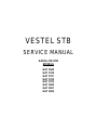
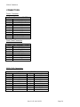
MODELS
SAT 3600
SAT 3700
SAT 3701
SAT 3702
SAT 3703
SAT 3800
SAT 3801
SAT 3802

SERVICE MANUAL
Rev 1.0 21.10.02 16:23 Page 2
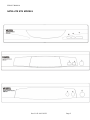
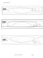
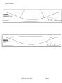
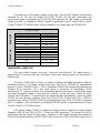
SATELLITE STB MODELS

SERVICE MANUAL
Rev 1.0 21.10.02 16:23 Page 3

SERVICE MANUAL
Rev 1.0 21.10.02 16:23 Page 4

SERVICE MANUAL
Rev 1.0 21.10.02 16:23 Page 5
SATELLITE STB MODELS......................................................................................................................................................2
REVISION HISTORY .................................................................................................................................................................6
GENERAL DESCRIPTION........................................................................................................................................................7
ST
I5518 (IC100)........................................................................................................................................................................7
SDRAM 8MB
YTE (IC300)......................................................................................................................................................23
F
LASH MEMORY 1 MBYTE (IC301)........................................................................................................................................23
EEPROM
S 128K (16,384 X 8) 2-WIRE SERIAL (IC302).........................................................................................................25
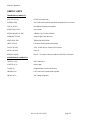
USED IC LISTS..........................................................................................................................................................................33
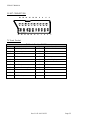
CONNECTORS..........................................................................................................................................................................34
P
OWER CONNECTOR..................................................................................................................................................................34
F
RONT PANEL CONNECTOR .......................................................................................................................................................34
5512 JTAG C
ONNECTORS.........................................................................................................................................................34
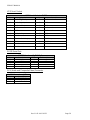
SCART CONNECTION...........................................................................................................................................................35
TV S
CART SOCKET...................................................................................................................................................................35
VCR S
CART SOCKET................................................................................................................................................................36
RS232 S
ERIAL PORT..................................................................................................................................................................36
RCA (A
UDIO AND COMPOSITE VIDEO) CONNECTOR.................................................................................................................36
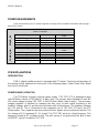
POWER REQUIREMENTS......................................................................................................................................................37
PCB EXPLANATIONS..............................................................................................................................................................37
INTRODUCTION...................................................................................................................................................................37
POWER BOARD (16PW07 E3) ............................................................................................................................................37
MAIN BOARD (16MB07 E3 )...............................................................................................................................................38
FRONT PANEL BOARD (TK507-2)....................................................................................................................................39
SERVICE MENU INTERFACE...............................................................................................................................................40
RF M
ODULATOR SYSTEM :........................................................................................................................................................40
RF M
ODULATOR TYPE :............................................................................................................................................................40
T
UNER TYPE :............................................................................................................................................................................40
S
CARTS :....................................................................................................................................................................................40
R
EBOOT :...................................................................................................................................................................................40
C
LEAR DATABASE :...................................................................................................................................................................41
L/R: DBC
OPY – OK: UPLOAD PGM :.......................................................................................................................................41
D
OWNLOAD PGM : ...................................................................................................................................................................42
R
EMOTE/FRONT TEST :..............................................................................................................................................................42
7-S
EGMENT DISPLAY TEST :......................................................................................................................................................43
S
YSTEM DIAGNOSTIC :...............................................................................................................................................................43
D
EVELOPMENT TEAM :..............................................................................................................................................................43
U
PLOAD DEFAULT SAT_XPDRS :...............................................................................................................................................43
D
OWNLOAD DEFAULT SAT_XPDRS : .........................................................................................................................................43
R
S232 TEST :.............................................................................................................................................................................44
SOFTWARE UPGRADE THROUGH RS232.........................................................................................................................45
SCHEMATICS............................................................................................................. ERROR! BOOKMARK NOT DEFINED.
BILL OF MATERIALS.............................................................................................................................................................48
BOARD LAYOUT....................................................................................................... ERROR! BOOKMARK NOT DEFINED.

SERVICE MANUAL
Rev 1.0 21.10.02 16:23 Page 6
REVISION HISTORY
Rev 1.0 07/25/02 Tuncay Akkurt Initial Revision
Schematics

SERVICE MANUAL
Rev 1.0 21.10.02 16:23 Page 7
GENERAL DESCRIPTION
Major functional blocks are discussed briefly in this section. A more detailed description is contained later in the
document.
STi5518 (IC100)
1. Introduction
The STi5518 integrates in a single chip: a transport demultiplex block; an ST20 32-bit system CPU; an
audio/video MPEG2 decoder; display and graphics features; a digital video encoder; and system peripherals. The
Sti5518 integrates DirecTV and DVB descramblers in the transport demultiplex block, allowing it to be used in both
Digital Video Broadcasting (DVB) and Digital Satellite System (DSS) set-top box applications.
2. Technical Specification
Integrated 32-bit host CPU up to 81 MHz
2 Kbytes of Icache, 2 Kbytes of Dcache, and 4 Kbytes of SRAM configurable as Dcache.
Audio decoder
5.1 channel Dolby Digital® /MPEG-2 multi-channel decoding, 3 X 2-channel PCM outputs
IEC60958 -IEC61937 digital output
SRS®/TruSurround®
DTS® digital out and MP3 decoding
Alignment beep for satellite dishes.
Video decoder
Supports MPEG-2 MP@ML
Fully programmable zoom-in and zoom-out
NTSC to PAL conversion.
DVD and SVCD subpicture decoder
High performance on-screen display
2 to 8 bits per pixel OSD options
Anti-flicker, anti-flutter and anti-aliasing filters.
PAL/NTSC/SECAM encoder
RGB, CVBS, Y/C and YUV outputs with 10-bit DACs
Macrovision® 7.01/6.1 compatible (optional).
Shared SDRAM memory interface
1 or 2x16-Mbit, or 1x64-Mbit 125 MH
Z SDRAM.
Programmable CPU memory interface for SDRAM, ROM, peripherals...
Front-end interface
DVD, VCD, SVCD and CD-DA compatible

SERVICE MANUAL
Rev 1.0 21.10.02 16:23 Page 8
Serial, parallel and ATAPI interfaces
Hardware sector filtering
Integrated CSS decryption and track buffer.
Hardware transport-stream demultiplexor
Parallel/serial input
DES and DVB descramblers
32 PID support.
Integrated peripherals
2 UARTs, 2 SmartCards, I
2C controller, 3 PWM outputs, 3 capture timers
Modem support
44 bits of programmable I/O
IR transmitter/receiver.
Professional toolset support
ANSI C compiler and libraries.
208 pin PQFP package.
The STi5518 is a highly integrated single-chip decoder, designed for use in feature-rich mass-market set-top boxes.
It integrates a high-performance 32-bit CPU, a dedicated block for DVB/DirecTV transport demultiplexing and
descrambling, modules for MPEG-2 video and audio decoding with 3D-surround and MP3 support, advanced
display and graphics features, a digital video encoder and all of the system peripherals required in a typical low-cost
interactive receiver. To cover the needs of DVD-capable set-top boxes, STi5518 integration options include a CSS
decryption block, a Dolby Digital audio decoder and Macrovision copy protection. An ATAPI interface is built-in,
supporting the glueless connection of standard Hard Disk Drives. In this way, the STi5518 is ideal for set-top boxes
featuring trick modes such as live TV recording, pausing and time-shifting. The STi5518 is backward compatible
with the popular STi5500 set-top box decoder, allowing easy migration from the previous generation. The high level
of integration in a single PQFP-208 package makes the STi5518 ideally suited for low-cost, high-volume set-top box
applications.

SERVICE MANUAL
Rev 1.0 21.10.02 16:23 Page 9
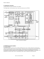
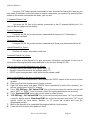
3. Architecture overview
The figure below shows the architecture of the Sti5518.
This chapter gives a brief overview of each of the functional blocks of the STi5518.
4. STi5518 functional modules
a. Central processor
The STi5518 Central Processing Unit is a ST20C2+ 32-bit processor core. It contains instruction processing logic,
instruction and data pointers, and an operand register. It directly accesses the high-speed on-chip SRAM, which
can store data or programs and uses the cache to reduce access time to off-chip program and data memory.
The processor can access memory via the Programmable CPU Interface (often referred to as the EMI) or the
Shared Memory Interface (SMI), which is shared with the video, audio, sub-picture and OSD decoders.

SERVICE MANUAL
Rev 1.0 21.10.02 16:23 Page 10
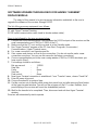
b. MPEG video decoder
This is a real-time video compression processor supporting the MPEG-1 and MPEG-2 standards at video rates up t
720 x 480 x 60 Hz and 720 x 576 x 50 Hz. Picture format conversion for display is performed by vertical and
horizontal filters. User-defined bitmaps can be super-imposed on the display picture by using the on-screen display
function. The display unit is part of the MPEG video decoder, it overlays the four display planes shown in the figure
below. The display planes are normally overlaid in the order illustrated, with the background color at the back and
the sub-picture at the front (used as a cursor plane). The sub-picture plane can alternatively be positioned between
the OSD and MPEG video planes where it can be used as a second on-screen display plane.
c. Audio decoder
The audio decoder accepts: Dolby Digital, MPEG-1 layers I, II and III, MPEG-2 layer II 6-channel, PCM, CDDA data
formats; MPEG2 PES streams for MPEG-2, MPEG-1, Dolby Digital, MP3, and Linear PCM (LPCM). The audio
decoder supports DTS® digital out (DVD DTS and CDDA DTS). SPDIF input data (IEC-60958 or IEC-61937
standards) is accepted if an external circuitry extracts the PCM clock from the stream. Skip frame, repeat blocks
and soft mute frame features can be used to synchronize audio and video data. PTS audio extraction is also
supported. The device outputs up to 6 channels of PCM data and appropriate clocks for external digital-to-analog
converters. Programmable downmix enables 1,2,3 or 4 channel outputs. Data can be output in either I²S format or
Sony format. The decoder can format output data according to IEC-60958 standard (for non compressed data: L/R
channels, 16, 18, 20 and 24-bits) or IEC-61937 standard (for compressed data), for F
S = 96 kHz, 48 kHz, 44.1 kHz
or 32 kHz. Sampling frequencies of 96 kHz, 48 kHz, 44.1 kHz, 32 kHz and half sampling frequencies are supported.
A downsampling filter (96 kHz/48 kHz) is available. The decoder supports dual mode for MPEG and Dolby Digital. It
includes a Dolby surround compatible downmix and a ProLogic decoder. A pink noise generator enables the
accurate positioning of speakers for optimal surround sound setup. PCM beep tone is a special mode used for Set
Top Box. It generates a triangular signal of variable frequency and amplitude on the left and right channels. In
global mute mode, the decoder decodes the incoming bitstream normally but the PCM and SPDIF outputs are
softmuted. This mode is used to prepare a period of decoding mode, to synchronize audio and video data without
hearing the audio. Slow-forward and fast-forward trick modes are available for compressed and non-compressed
data. The control interface of the decoder is activated via memory mapped registers in the ST20 address space.
d. IR transmitter/receiver
The STi5518 provides a pulse-position modulated signal for automatic VCR programming by the set-top box. The
signal is output to the IR blast pin and an accessory jack pin, simultaneously. The pulse frequency, number of
pulses (envelope length) and the total cycle time is controlled by registers.
e. Modem analog front-end interface
The Modem Analog Front-end interface is used to transfer transmit and receive DAC and ADC samples between
the memory and an external modem analog front-end (MAFE), using a synchronous serial protocol. DMA is used to
transfer the sample data between memory buffers and the MAFE interface module, with separate transmit and
receive buffers and double buffering of the buffer pointers. FIFOs are used to take into account the access latency
to memory, in a worst case system and to allow the use of bursts for memory bandwidth efficiency improvement.
The V22 bis standard is supported.
f. Memory subsystem
On-chip
The on-chip memory includes 2Kbytes of instruction cache, 2Kbytes of data cache and 4Kbytes of SRAM that can
be optionally configured as data cache. The subsystem provides 240M/bytes of internal bandwidth, supporting
pipelined 2- cycle internal memory access. The instruction and data caches are direct-mapped, with a write-back
system for the data-cache. The caches support burst accesses to the external memories for refill and write-back.
Burst access increases the performance of pagemode DRAM memories.
Off-chip
There are two off-chip memory interfaces:
• The external memory interface (EMI) accessed by the ST20 is used for the transfer of data and programs
between the STi5518 and external peripherals, flash and additional SDRAM and DRAM.

SERVICE MANUAL
Rev 1.0 21.10.02 16:23 Page 11
• Shared memory interface (SMI) controls the movement of data between the STi5518 and 16, 32 or 64 Mbits of
SDRAM. This external SDRAM stores the display data generated by the MPEG decoder and CPU and the C2+
code data.
The EMI uses minimal external support logic to support memory subsystems, and accesses a 32 Mbytes of physical
address space (greater if SDRAM or DRAM is used) in four general purpose memory banks of 8 or 16 bits wide, 21
or 22 address lines, and byte select. For applications requiring extra memory, the EMI supports this extra memory
with zero external support logic, even for 16-bit SDRAM devices. The EMI can be configured for a wide variety of
timing and decode functions by the configuration registers. The timing of each of the four memory banks can be set
separately, with different device types being placed in each bank with no need for external hardware.
g. Serial communication
Asynchronous serial controllers
The Asynchronous Serial Controller (ASC), also referred to as the UART interface, provides serial communication
between the STi5518 and other microcontrollers, microprocessors or external peripherals. The STi5518 has four
ASCs, two of which are generally used by the SmartCard controllers.
Eight or nine bit data transfer, parity generation, and the number of stop bits are programmable. Parity, framing, and
overrun error detection increase data transfer reliability. Transmission and reception of data can be double-buffered,
or 16-deep FIFOs can be used. A mechanism to distinguish the address from the data bytes is included for
multiprocessor communication. Testing is supported by a loop-back option. A 16-bit baud-rate generator provides
the ASC with a separate serial clock signal.
Two ASCs support full-duplex and 2 half-duplex asynchronous communication, where both the transmitter and the
receiver use the same data frame format and the same baud rate. Each ASC can be set to operate in SmartCard
mode for use when interfacing to a SmartCard.
Synchronous serial controller
Two Synchronous Serial Controllers (SSC) provide high-speed interfaces to a wide variety of serial memories,
remote control receivers and other microcontrollers. The SSCs support all of the features of the Serial Peripheral
Interface bus (SPI) and the I
2C bus. The SSCs can be programmed to interface to other serial bus standards. The
SSCs share pins with the parallel input/output (PIO) ports, and support half-duplex synchronous communication.
h. Front-end interface
The STi5518 can be connected to a front-end through the following interfaces:
• I2S interface;
• multi-format serial interface;
• multi-format parallel interface;
• ATAPI interface (for Hard Disk Drives and DVD-ROMs)
i. On-chip PLL
The on-chip PLL accepts 27 MHz input and generates all the internal high-frequency clocks needed for the CPU,
MPEG and audio subsystems.
j. Diagnostic controller (DCU)
The ST20 Diagnostic Controller Unit (DCU) is used to boot the CPU and to control and monitor the chip systems via
the standard IEEE 1194.1 Test Access Port. The DCU includes on-chip hardware with ICE (In Circuit Emulation)
and LSA (Logic State Analyzer) features to facilitate verification and debugging of software running on the on-chip
CPU in real time. It is an independent hardware module with a private link from the host to support real-time
diagnostics.
k. Interrupt subsystem
The interrupt system allows an on-chip module or external interrupt pin to interrupt an active process so that an

SERVICE MANUAL
Rev 1.0 21.10.02 16:23 Page 12
interrupt handling process can be run. An interrupt can be signalled by one of the following: a signal on an external
interrupt pin, a signal from an internal peripheral or subsystem, software asserting an interrupt in the pending
register. Interrupts are implemented by an on-chip interrupt controller and an on-chip interrupt-level controller. The
interrupt controller supports eight prioritized interrupts as inputs and manages the pending interrupts. This allows
the nesting of pre-emptive interrupts for real-time system design. Each interrupt can be programmed to be at a
lower or higher priority than the high priority process queue.
l. PAL/NTSC/SECAM encoder
The integrated digital encoder converts a multiplexed 4:2:2 or 4:4:4 YCbCr stream into a standard analog baseband
PAL/NTSC or SECAM signal and into RGB, YUV, Yc and CVBS components. The encoder can perform closed-
caption, CGMS encoding, and allows Macrovision
TM 7.01/6.1 copy protection. The DENC is able to encode Teletext
according to the “CCIR/ITU-R Broadcast Teletext System B” specification, also known as “World System Teletext”.
In DVB applications, Teletext data is embedded within DVB streams as MPEG data packets. It is the responsibility
of the software to handle incoming data packets and in particular to store Teletext packets in a buffer, which then
passes them to the DENC on request.
m. SmartCard interfaces
Two SmartCard interfaces support SmartCards compliant with ISO7816-3. Each interface is has a UART (ASC), a
dedicated programmable clock generator, and eight bits of parallel IO port.
n. PWM and counter module
The PWM and counter module provides three PWM encoder outputs, three PWM decoder (capture) inputs and four
programmable timers. Each capture input can be programmed to detect rising edge, falling edge, both edges or
neither edge (disabled). These facilities are clocked by two independent clocks, one for PWM outputs and one for
capture inputs/timers. The PWM counter is 8-bit, with 8-bit registers to set the output-high time. The
capture/compare counter and the compare and capture registers are 32-bit. The module generates a single
interrupt signal.
o. Parallel I/O module
44 bits of parallel I/O are configured in 6 ports, and each bit is programmable as output or input. The output can be
configured as a totem-pole or open-drain driver. The input compare logic can generate an interrupt on any change
of any input bit. Many parallel IO have alternate functions and can be connected to an internal peripheral signal
such as a UART or SSC.

SERVICE MANUAL
Rev 1.0 21.10.02 16:23 Page 13
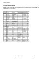
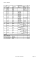
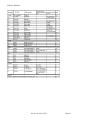
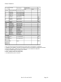
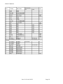
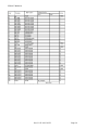
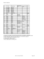
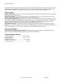
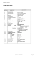
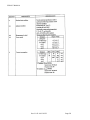
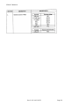
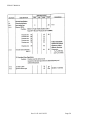
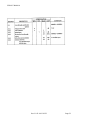
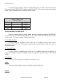
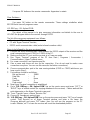
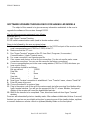
5. Pin list sorted by function
Alternate functions printed in Italic show a suggested use of the PIO; alternate functions not printed in Italic are
multiplexed with a specific hardware.

SERVICE MANUAL
Rev 1.0 21.10.02 16:23 Page 14

SERVICE MANUAL
Rev 1.0 21.10.02 16:23 Page 15

SERVICE MANUAL
Rev 1.0 21.10.02 16:23 Page 16
1. FEI_CFG bits 8 and 9 must be programmed according to the required NRSS configuration.
2. The NRSS_IN and NRSS_OUT pins are swapped around on the STi5518 compared to the STi5508.
3. Register LNK_SDAV_CONF bit 22 (SDE) must be set to 1 to validate the output path.
4. Inverted. ATTENTION! the PIO input is also inverted.
5. The PIO must be configured in open drain.
6. BOOT_FROM_ROM is active during reset.
7. Tie low whenever JTAG is not used.

SERVICE MANUAL
Rev 1.0 21.10.02 16:23 Page 17
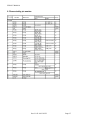
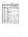
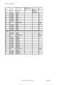
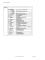
6. Pins sorted by pin number

SERVICE MANUAL
Rev 1.0 21.10.02 16:23 Page 18

SERVICE MANUAL
Rev 1.0 21.10.02 16:23 Page 19

SERVICE MANUAL
Rev 1.0 21.10.02 16:23 Page 20
Page is loading ...
Page is loading ...
Page is loading ...
Page is loading ...
Page is loading ...
Page is loading ...
Page is loading ...
Page is loading ...
Page is loading ...
Page is loading ...
Page is loading ...
Page is loading ...
Page is loading ...
Page is loading ...
Page is loading ...
Page is loading ...
Page is loading ...
Page is loading ...
Page is loading ...
Page is loading ...
Page is loading ...
Page is loading ...
Page is loading ...
Page is loading ...
Page is loading ...
Page is loading ...
Page is loading ...
Page is loading ...
Page is loading ...
Page is loading ...
Page is loading ...
Page is loading ...
Page is loading ...
-
 1
1
-
 2
2
-
 3
3
-
 4
4
-
 5
5
-
 6
6
-
 7
7
-
 8
8
-
 9
9
-
 10
10
-
 11
11
-
 12
12
-
 13
13
-
 14
14
-
 15
15
-
 16
16
-
 17
17
-
 18
18
-
 19
19
-
 20
20
-
 21
21
-
 22
22
-
 23
23
-
 24
24
-
 25
25
-
 26
26
-
 27
27
-
 28
28
-
 29
29
-
 30
30
-
 31
31
-
 32
32
-
 33
33
-
 34
34
-
 35
35
-
 36
36
-
 37
37
-
 38
38
-
 39
39
-
 40
40
-
 41
41
-
 42
42
-
 43
43
-
 44
44
-
 45
45
-
 46
46
-
 47
47
-
 48
48
-
 49
49
-
 50
50
-
 51
51
-
 52
52
-
 53
53


VESTEL SAT 3702 User manual
- Type
- User manual
Ask a question and I''ll find the answer in the document
Finding information in a document is now easier with AI
Related papers
Other documents
-
Hitachi HTD-K185UK User manual
-
Orbit XTRA DIGITAL-XD300 User manual
-
Texas Instruments TVP5160EVM Users User manual
-
-
Bauhn 6-Way Surge Powerboard User guide
-
Cyrus CYRUS 8 User manual
-
York Fitness 5000 - UK User manual
-
König KN-VC003R Datasheet
-
Extron electronics SMD 101 User manual
-
Intel 80C196NU User manual