
TCY-FT-U
Temperature PID controller
Doc: 70-00-0128B, V1.2, 20110621 © Vector Controls GmbH, Switzerland Page 1
Subject to alteration
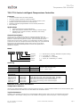
TCY-FT-U Series Intelligent Temperature Controller
Features
• Temperature PID control for HVAC systems.
• Up to two 3-point outputs for 24VAC actuators.
• 1 internal temperature sensor and up to 2 external sensor inputs
• Multiple remote control functions on external input
• Password protected programmable user and control parameters
• Blue backlight
Applications
• Various temperature control applications
• Water Only Systems: Radiator, floor heating or chilled ceilings
• Individual room control for offices, residential, hotel rooms,
meeting rooms, etc.
General Description
The TCY-FT-U is a stand-alone electronic universal controller with one
temperature control loop. It may use up to 2 PID sequences. The TCY-FT-U
features 1 internal NTC temperature sensor, up to two external sensors
inputs and up to four binary outputs. The configuration has been reduced to
a minimum to allow for a simple and off the shelf usage. For more advanced
features the TCI product range may be used. The TCY-FT-U can be
configured using the standard operation terminal. No special tool or
software is required.
Name
Ordering
Item Name Item code Control Type Key-data
TCY-FT2-U-W01 40-10 0068-1 Cooling only
Compact PID controller with:
2 TI, 1 3-point output
TCY-FT2-U-W02 40-10 0068-2 Heating only
TCY-FT2-U 40-10 0068 2-Pipe system
TCY-FT4-U 40-10 0072 4-Pipe system 1 TI, 2 3-point outputs
Accessories
S-Tn10-2
SD-Tn10-12-2
SD-Tn10-20-2
SDB-Tn10-12
SDB-Tn10-20
SRA-Tn10
40-20 0001
40-20 0002
40-20 0003
40-20 0051
40-20 0004
40-20 0005
Flying lead sensor with 2 m cable
Flying lead duct sensor 12cm immersion depth, 2m cable
Flying lead duct sensor 20cm immersion depth, 2m cable
Duct sensor with housing, 12cm immersion depth
Duct sensor with housing, 20cm immersion depth
Room sensor
Selection of actuators and sensors
Temperature Sensors:
Use only our approved NTC sensors to achieve maximum accuracy. Recommended is SDB-Tn10-20 as Duct sensor, SRA-
Tn10 as Room sensor and SDB-Tn10-20 with AMI-S10 as immersion sensor.
3-point Actuators:
Actuators with constant running time are recommended. Observe power limits. Do not use actuators with power
consumption > 6VA. Adjust running time in SW. Default running time is 90s for fully open / close running time.
Housing: U = Vertical (2x4”) housing, Standard is square housing
Function: 2 = 2 = 2-Pipe, 4 = 4-Pipe
Input: T = Temperature, H = Humidity
Output: F = 3-point, M = Modulating, B = Binary
Series: TCY
T C
Y
T
-
F
-
U
(
)
2

TCY-FT-U
Technical Specifications
Doc: 70-00-0128B, V1.2, 20110621 © Vector Controls GmbH, Switzerland Page 2
Subject to alteration
Technical specifications
Power Supply
Operating Voltage 24 V AC ± 10 %, 50…60 Hz, Class 2, 48VA max
Power Consumption Max. 1.5 VA
Electrical Connection Terminal Connectors,
wire 0.34…2.5 mm
2
(AWG 24…12)
Signal inputs
Temperature Input
Range
Accuracy
0…50 °C (32…122 °F)
0.5 K
Signal outputs
TRIAC Outputs
Switching power
24 VAC, 250mA max
Do not use actuators with power consumption > 6VA
Environment
Operation
Climatic Conditions
Temperature
Humidity
To IEC 721-3-3
class 3 K5
0…50 °C (32…122 °F)
<95 % r.H. non-condensing
Transport & Storage
Climatic Conditions
Temperature
Humidity
Mechanical Conditions
To IEC 721-3-2 and IEC 721-3-1
class 3 K3 and class 1 K3
-25…70 °C (-13…158 °F)
<95 % r.H. non-condensing
class 2MT2
Standards
conform according to
EMC Standard 89/336/EEC
EMEI Standard 73/23/EEC
EN 61 000-6-1/ EN 61 000-6-3
Product standards
Automatic electrical controls for
household and similar use
Special requirement on temperature
dependent controls
EN 60 730 –1
EN 60 730 – 2 – 9
Degree of Protection IP30 to EN 60529
Safety Class III (IEC 60536)
Cover, back part
Mounting Plate
Fire proof ABS plastic (UL94 class V-0)
Galvanized Steel
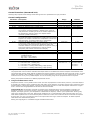
General
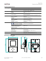
Dimensions (H x W x D) Front part: 112 x 73 x 15 mm (4.4” x 2.9” x 0.6”)
Power case: ø 58 x 32 mm (ø 2.3” x 1.3”)
Weight (including package) 260 g (9.2 oz)
Dimensions [mm] (inch)
58 (2.3)
112 (4.4)
73
(
2.9
)
32
(
1.2
)
15
(
0.6
)

TCY-FT-U
Technical Specifications
Doc: 70-00-0128B, V1.2, 20110621 © Vector Controls GmbH, Switzerland Page 3
Subject to alteration
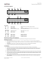
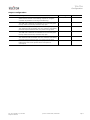
Connection diagram
Description:
G0 0V Power supply: 0VAC, internally connected to signal common
G 24V Power supply: 24VAC
M 0V Signal common: Common 0 potential for analog inputs and analog outputs.
X1 RT External temperature input: NTC 10kΩ @ 25°C (77°F)
TCY-FT2-U:
X2 CO Change over input: NTC 10kΩ @ 25°C (77°F)
Y1 DO1 Binary output: Valve open
Y2 DO2 Binary output: Valve close
TCY-FT4-U:
Y1 DO1 Binary output: Heating valve open
Y2 DO2 Binary output: Heating valve close
Y3 DO3 Binary output: Cooling valve open
Y4 DO4 Binary output: Cooling valve close
Mechanical Design and installation
The unit consists of two parts: (a) The power case with attached mounting plate and (b) the front part.
Mounting location
• On an easy accessible interior wall, approx. 1.5 m (4.5’) above the floor in an area of average temperature.
• Avoid exposure to direct sunlight or other heat sources, e.g. the area above radiators and heat emitting electrical
equipment.
• Avoid locations behind doors, outside walls and below or above air discharge grills and diffusers.
• Location of mounting is less critical if external temperature sensors are used
Installation
1. Connect the wires to be connected to the terminals of the power case according to wiring diagram
2. Install the mounting plate to the flush mounting box. Make sure that the nipple with the front holding screw is
facing to the ground. Make sure the mounting screw heads do not stand out more than 5 mm (0.2”) off the
surface of the mounting plate.
3. Ensure that the jumpers are set correctly.
4. Slide the two latches located on the top of the front part into the hooks at the upper side of the mounting plate.
5. Carefully lower the front part until the interconnector reaches the mounting-plate. Continue pressing in a gentle
way until the front part is fully connected. While inserting the connectors, a slight resistance can be felt. This is
normal. Do not use excessive force!
6. With a Philips-type screw driver of size #2, carefully tighten the front holding screw to secure the front part to
the mounting plate. This screw is located on the front lower side of the unit. There is no need to tighten the
screw too much
X
T INT
0V (COM)
24V AC/DC
2
G
TCY-FT4-U
1
G0
3
Y1
Heat
OPEN
4
Y2
Heat
CLOSE
7
M
Signal
COM
8
X1
X
T EXT
IN
5
Y3
Cool
OPEN
6
Y4
Cool
CLOSE
X
T INT
0V (COM)
24V AC/DC
2
G
TCY-FT2-U
1
G0
3
Y1
OPEN
4
Y2
CLOSE
X
T CO
IN
6
X2
COM
5
M
8
X1
X
T EXT
IN
7
M
COM

TCY-FT-U
Operation Instructions
Doc: 70-00-0128B, V1.2, 20110621 © Vector Controls GmbH, Switzerland Page 4
Subject to alteration
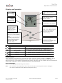
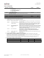
Display and Operation
Operation mode
Comfort (occupied) All control functions operating per set points.
Economy (unoccupied):
Set points shifted according to Parameters CP04.
Economy mode and setpoint shift may be disabled with UP07
OFF
Energy Hold Off Outputs are off, inputs monitored for alarm condition
Heating Output activates if temperature lower than setpoint
Cooling Output activates if temperature higher than setpoint
Power Failure
All the parameters and set points are memorized and do not need to be reentered. Depending on UP05 the unit will
remain switched off, switch on automatically or return to the operation mode it was in before the power failure.
Deluxe version only: Timer operation and daytime setting will be retained for 24h. The controller has to be connected to a
power supply for at least 10 hours for the backup function to operate accordingly.
Error messages
The TCY-FT-U may display the following error condition:
Err1: The connection to the temperature sensor may be interrupted or the temperature sensor is damaged.
The output is switched off. Verify parameter settings and wiring.
Left (POWER)
Press < 2 sec.: Toggle STANDBY-
COMFORT mode or switch from OFF
to ON
Press > 2 sec.: Turn unit OFF. Text
OFF displayed with current time
(deluxe) temperature (standard)
(Parameter setting: ENTER to
select menu option, accept
parameter change)
Up
Increment SET POINT
(Parameter setting:
SCROLL menu options
and parameters)
Down
Decrement SET POINT
(Parameter setting: SCROLL menu
options and parameters)
Mode
Display of operation
mode
Large Digits
Display of input or parameter
value.
Indicators
1 Remote
temperature sensor
2 Dew point sensor
Vertical Bar
(scrolls up/down, 10% resolution)
Small Digits
Display of setpoint, clock or
parameter number.
Right (OPTION)
Press < 2 sec.: Select Control Loop
Press > 2 sec.: Manual H/C change
(Parameter setting: ENTER to
select menu option, accept
parameter change)

TCY-FT-U
Configuration
Doc: 70-00-0128B, V1.2, 20110621 © Vector Controls GmbH, Switzerland Page 5
Subject to alteration
Configuration parameters for firmware version 1.2
The TCY-FT-U is preset to work for most applications. For special requirements it can be fine tuned to work ideally with a
simple parameter setup routine. The parameters can be changed on the unit without the need of additional equipment.
Identifying the firmware version
The parameters and functionality of controller depend on its firmware version and revision. It is therefore important to use
a matching product version and parameter set. The Firmware version and revision version can be found when pressing
simultaneously the S and T keys during several seconds. On the upper 7 segment display, the firmware version can be
found, on the lower 7 segment display the current revision index (or “sub-version”).
Access to parameters
The TCY-FT-U is an intelligent controller and can be adapted to fit perfectly into your application. The control operation is
defined by parameters. The parameters are set during operation by using the standard operation terminal.
The parameters are password protected. There are two levels of parameters: User operation parameters for access control
settings and Expert parameters for control functions and unit setup. The passwords for user levels and expert levels are
different. Only control experts should be given the control parameter password.
The parameters can be changed as follows:
1. Press UP and DOWN button simultaneously for three seconds. The display will indicate the firmware version in the
upper large digits and the revision in the lower small digits. Pressing any key will show: CODE.
2. Select a password using UP or DOWN buttons. Select 009 in order to get access to the user parameters, 241 for
controls parameters.
Press OPTION after selecting the correct password.
3. Once logged in, the parameter is displayed immediately
4. Select the parameters with the UP/DOWN keys. Change a parameter by pressing the OPTION key. The MIN and
MAX symbols show up and indicate that the parameter may be modified now. Use UP and DOWN key to adjust
the value.
5. After you are done, press OPTION or POWER in order to return to the parameter selection level.
6. Press the POWER key again so as to leave the menu. The unit will return to normal operation if no key is pressed
for more than 5 minutes.
User Parameters (Password 009)
Parameter Description Range Default
UP 00 Enable access to operation modes ON, OFF ON
UP 01 Enable access to set points ON, OFF ON
UP 02 Not used ON, OFF OFF
UP 03 Enable manual change of Heating/Cooling Mode.
No influence on TCY-FT2-U-W1 (cooling only) or TCY-FT2-U-
W2 (heating only)
ON, OFF ON
UP 04 Not used ON, OFF OFF
UP 05 State after power failure:
0 = off, 1 = on, 2 = state before power failure
0, 1, 2 2
UP 06
Enable Economy (unoccupied) Mode.
Shift the setpoint to a lower temperature in winter or higher
temperature in summer in order to save energy. May be
activated through the POWER button, or with the external
input (typically for key card switches in hotel rooms or motion
detectors for meeting rooms.)
ON, OFF ON
UP 07 ON = Fahrenheit, OFF = Celsius ON, OFF OFF (Celsius)
UP 08 Calibrate internal temperature sensor
–10° to +10° in 0.1° steps. (Sensor is factory calibrated, use
this feature for field adjustment only as required.)
-10…10 0.0
UP 09 Enable Frost Protection.
Activates the output independent of operation mode when the
control temperature drops below 5°C or 41°F. The controller
returns to normal operation when the temperature increases
above 10°C or 50°F.
ON, OFF TCY-FT2-U-W1:
OFF
TCY-FT2-U-W2:
ON
TCY-FT2-U: ON
TCY-FT4-U: ON

TCY-FT-U
Configuration
Doc: 70-00-0128B, V1.2, 20110621 © Vector Controls GmbH, Switzerland Page 6
Subject to alteration
Control Functions (Password 241)
Warning! Only experts should change these settings! See user parameters for login procedure.
Control configuration
Parameter Description Range Default
CP 00 Minimum setpoint limit in heating mode 0-60°C (32-160°F) 16°C (61°F)
CP 01 Maximum setpoint limit in heating mode 0-60°C (32-160°F) 30°C (86°F)
CP 02 Minimum setpoint limit in cooling mode 0-60°C (32-160°F) 18°C (65°F)
CP 03 Maximum setpoint limit in cooling mode 0-60°C (32-160°F) 30°C (86°F)
CP 04 Economy (unoccupied) Mode temperature shift:
The comfort (occupied) setpoint is shifted by the value set
with parameter. If heating is active the comfort setpoint will
be decreased, if cooling is active, the setpoint will be
increased. (Enable with UP06.)
0-100°C (200°F) 5.0°C (10°F)
CP 05 Dead Zone Span (TCY-FT4-U only):
The Dead Zone Span lies between the heating and the cooling
setpoint. The output is off while the temperature is within the
dead zone span. A negative dead zone is not possible.
0-100°C (200°F) 1.0°C (2°F)
CP 06
Heat/Cool Changeover Delay (TCY-FT4-U only):
A demand to switch between heating and cooling must persist
for the length of time set with this parameter before the
controller switches. Prevents activation of a sequence during a
short-term change in temperature in order to protect
equipment (with control overshoot for example)
0-255 min 5 min
CP 07 P-band heating X
PH
0-100°C (200°F) 2.0°C (4.0°F)
CP 08 P-band cooling X
PC
0-100°C (200°F) 2.0°C (4.0°F)
CP 09 K
IH
, Integral gain heating, in 0.1 steps, (TI is fixed to 4s)
0 disables ID part
low value = slow reaction
high value = fast reaction
0…25.5 0.0
CP 10 K
IC
, Integral gain cooling, in 0.1 steps, 0 disables I part 0…25.5 0.0
CP 11 Configuration of operation mode
0 = TCY-FT2-U-W1 = Cooling only
1 = TCY-FT2-U-W2 = Heating only
2 = TCY-FT2-U = Heating and Cooling (2 pipe system)
3 = TCY-FT4-U = Heating and Cooling (4 pipe system)
TCY-FT2-U: 0 - 2
TCY-FT4-U: 0 – 3
TCY-FT2-U-W1: 0
TCY-FT2-U-W2: 1
TCY-FT2-U: 2
TCY-FT4-U: 3
Î Proportional control (P-band)
The proportional control function calculates the output based on the difference between setpoint and measured value.
The proportional band (P-band) defines the difference between setpoint and measured value which will result in a 100%
output. For example, with a heating or reverse 0-10v control sequence, and a 2.0°C (4.0°F) P-band value, at 10v the
controller will be 2.0°C (4.0°F) below setpoint. This is the working range of the proportional control sequence.
Setting the proportional band to 0 disables proportional control.
Î Integral and Differential control
Proportional control is a very stable control mode. The flaw of proportional control alone, however, is that the setpoint
is normally not reached. As the measured value gets closer to the setpoint, the output reduces until it reaches a point,
a fraction above or below the setpoint, where the output equals the load. To reach the setpoint and achieve a higher
level in comfort the Integral/Differential function should be activated.
Integral Gain (KI) dynamically increases the output by the selected KI value until the setpoint is reached. The
challenge, however, is to prevent hunting, where the output increases too fast, the temperature overshoots the
setpoint, the output goes to 0, the temperature undershoots the setpoint, and the cycle repeats itself. Hunting may
result if the integral gain is too high. Each system is different. It is recommended to start with a KI value of 0.5 for
water based systems and 1.0 for air based systems. Reduce this value if the measured value overshoots the setpoint
by more than 1°C (2°F). Increase the value if the output takes too long to reach the setpoint. Air based systems
react faster than water based systems.
Setting the integral gain to 0 disables integral and differential control.

TCY-FT-U
Configuration
Doc: 70-00-0128B, V1.2, 20110621 © Vector Controls GmbH, Switzerland Page 7
Subject to alteration
Output configuration
Parameter Description Range Default
CP 12 Manual Override Mode:
Allows manual control of the floating outputs for using the
controller as positioner or during commissioning.
ON, OFF OFF
CP 13 Running time FO1 (TCY-FT4-U = heating output)
The total time it takes for the actuator to run from fully open
to fully closed or from fully closed to fully open
0-255s 90s
CP 14 Minimum running time FO1 (TCY-FT4-U = heating output)
The minimum time the output runs once it starts. This setting
prevents frequent switches with very short running times.
0-255s 3s
CP 15 Running time FO2 (TCY-FT4-U = cooling output)
The total time it takes for the actuator to run from fully open
to fully closed or from fully closed to fully open
0-255s 90s
CP 16 Minimum running time FO2 (TCY-FT4-U = cooling output)
The minimum time the output runs once it starts. This setting
prevents frequent switches with very short running times.
0-255s 3s
CP 17
Maximum Output in Economy (unoccupied) Mode
Reduces the load on the system when is the space is
unoccupied.
0 – 100 % 50%

TCY-FT-U
Configuration
Doc: 70-00-0128B, V1.2, 20110621 © Vector Controls GmbH, Switzerland Page 8
Subject to alteration
Input configuration
Parameter Description Range Default
CP 18 Configuration of remote input (X1)
0 = Control Input
1 = Comfort/Economy Mode switch
2 = Comfort/OFF Mode switch
3 = Keycard switch function
4 = Output enable
0…4 0
CP 19 Activation delay (minutes):
The time the binary input needs to be open before Economy or
OFF mode is activated.
0…255 min 5
CP 20 Fixed setpoint for key card function in heating mode 0–60°C (32..160°F) 17°C (63°F)
CP 21 Fixed setpoint for key card function in cooling mode 0–60°C (32..160°F) 27°C (81°F)
CP 22 For TCY-FT2-U only: Enable Auto changeover ON, OFF OFF
CP 23 For TCY-FT2-U only: Auto changeover limit heating 0–60°C (32..160°F) 30°C (86°F)
CP 24 For TCY-FT2-U only: Auto changeover limit cooling 0–60°C (32..160°F) 15°C (59°F)
Î Configuring the function of the external input X1
The external input X1 may be configured for several functions:
CP18 = 0 External control input The control input is provided by the external input. The internal input
will not be used.
CP18 = 1 Switching Economy and
Comfort modes
Economy (unoccupied) and Comfort (occupied) modes are controlled
through an external contact by connecting X1 through a dry contact to
signal common. This function may be used together with key card
switches for hotels or motion detectors for offices.
CP18 = 2 Switching Energy Hold
OFF and Comfort
modes
Opening the external temperature input will force the unit into the OFF
operation mode. The operation mode cannot be overridden by using the
terminal. Connecting the binary input to GND returns control of the
operation mode to the terminal. This function may be used as window
contact to prevent loss of energy.
CP18 = 3 Key card function As with CP18 = 1, the key card function switches economy
(unoccupied) and comfort (occupied) modes. Instead of using the
setpoint shift, the setpoints in unoccupied mode are defined by
parameter CP20 and CP21.
CP18 = 4 Output enable / Dew
point sensor
This may be used for a dew point sensor input. Output will switch off if
contact opens.
Î Configuring auto changeover input X2 (TCY-FT2-U only):
The auto changeover function automatically changes heating and cooling mode based on supply media
temperature or outdoor temperature. The difference between the two is in the values of the changeover limits
CP23 and CP24. See table below for recommended settings.
Heating and cooling may be as well changed by an open contact switched to signal ground. Note: all signal
ground levels of involved controllers must be the same in case more than one controller is switched.
Î Recommended settings for CP23 and CP24:
Change over mode Relation CP23 to CP24 Example CP23 Example: CP24
Supply media CP23 > CP24 25°C (77F) 18°C (64F)
Outside temperature CP23 < CP24 15°C (59F) 25°C (77F)
Dry contact: Heating if contact closed CP23 > CP24 25°C (77F) 15°C (59F)
Dry contact: Cooling if contact closed CP23 < CP24 15°C (59F) 25°C (77F)
-
 1
1
-
 2
2
-
 3
3
-
 4
4
-
 5
5
-
 6
6
-
 7
7
-
 8
8


Vector TCY-FT4-U User manual
- Type
- User manual
- This manual is also suitable for
Ask a question and I''ll find the answer in the document
Finding information in a document is now easier with AI
Related papers
-
Vector TCY-FT-U User manual
-
-
-
-
-
-
-
-
-
Vector TLC-FCR-2-D-W01 User manual
Other documents
-
Siemens RDD10 Series Operating Instructions Manual
-
 Digital Watchdog DW-CP04 User manual
-
Unbranded 10103 User manual
-
Honeywell T2798I2000 User manual
-
 Xtend and Climb FT-4 User guide
-
Intel UPI-C42 User manual
-
Walton UH-301 Owner's manual
-
Omega TCY 60 and TCY 90 Owner's manual
-
Omega Engineering 20 User manual
-

