Page is loading ...

Mitsubishi Electric Air Conditioning Network System
Integrated centralized control software TG-2000A(Ver. 2)
Operation Manual (Site adjustment)
Please read this manual before using the unit.
Please keep this manual for future use. WT03901X01
2002-Sep. (Ver. 2.00)
Contents
1. Safety Precautions................................1
2. System Requirements............................2
3. System Configuration.............................5
4. Flow of Site Adjustment..........................6
5. Installation .........................................9
6. Part Names and Functions.....................13
7. Initial Startup and Shutdown...................20
8. System Setting Procedure.....................22
8.1 System Setting Screen...................22
8.2 System Setting Procedure...............22
8.3 User Set-up................................23
8.4 Site Name Set-up.........................25
8.5 G-50A Connection Set-up...............27
8.6 System Configuration Set-up............28
8.7 Monitoring screen Set-up................34
8.8 Watt Hour Meter Set-up..................40
8.9 Energy monitoring Set-up................42
8.10 Time Set-up...............................50
8.11 Password Change........................52
9. Charge Data Correction and Remedy ........53
9.1 Result of Air-conditioning
Charge Calculation.......................53
9.2 Maintenance of Charge Data............55
9.3 Operation Amount Data Monitoring.....60
9.4 Charge Parameter Output...............61
9.5 Charging Remedy ........................62
10. Error code list....................................74
11. Setting Check List .............................78
Appendix 1 Installing Windows XP
Professional ........................91
Appendix 2: Auto Log-in Confirmation Method.93
Appendix 3: Correction to Charge Calcution
in the Event of G-50A
Replacement due to Fault..........94

Contents
1. Safety Precautions..............................................1
2. System Requirements..........................................2
2.1 Requirements (system recommendations)............2
2.2 Compatible units..........................................2
2.3 Restrictions................................................3
2.4 Other devices .............................................4
3. System Configuration...........................................5
3.1 System Configuration Example.........................5
3.2 Hardware Connection Diagram.........................5
4. Flow of Site Adjustment........................................6
4.1 Flow of Site Adjustment..................................6
4.2 Tools for Site Adjustment................................6
4.3 Step 1: Test operation from central controller
G-50A ............................................7
4.4 Step 2: Initial setting of integrated centralized
control software TG-2000A.....................7
4.5 Step 3: Test operation from integrated centralized
control software TG-2000A.....................8
5. Installation.......................................................9
5.1 Pre-installation Steps ....................................9
5.2 TG-2000A Setup.........................................9
5.2.1 Setup...............................................9
5.2.2 Running TG-2000A Setup (New setup)......10
5.3 TG-2000A Uninstall....................................12
6. Part Names and Functions...................................13
6.1 Window Elements......................................13
6.2 Basic Mouse Operation................................14
6.3 Accessing Functions and Moving between
Windows.................................................14
7. Initial Startup and Shutdown.................................20
7.1 Before startup...........................................20
7.2 Startup...................................................20
7.3 Shutdown................................................21
8. System Setting Procedure...................................22
8.1 System Setting Screen................................22
8.2 System Setting Procedure.............................22
8.3 User Set-up .............................................23
8.3.1 General Operation..............................23
8.3.2 Connection Setting.............................24
8.3.3 Reliability Function.............................24
8.3.4 Energy Monitoring Related....................25
8.4 Site Name Set-up......................................25
8.5 G-50A Connection Set-up.............................27
8.5.1 Setting Procedure and Restrictions...........27
8.5.2 Number of G-50A (Step1) .....................27
8.5.3 G-50A IP Address Set-up (Step 2)............27
8.6 System Configuration Set-up..........................28
8.6.1 Setting Procedure and Restrictions...........28
8.6.2 G-50A Data Collecting (Step 1)...............29
8.6.3. Unit Composition Set-up (Step 2).............29
8.6.4. Set-up of Refrigerant System (Step3) ....31
8.6.5 Set-up of Group (Step4).......................32
8.6.6 Interlocked setting(Step 5).....................33
8.7 Monitoring Screen Set-up.............................34
8.7.1 Configuration Procedure and Restrictions ...34
8.7.2 Set-up of Model Name (Step1)................34
8.7.3 Set-up of the Number of Floors,
and Floor Name (Step2).......................35
8.7.4 Creation of a Plane View (Step 3).............36
8.7.5 Set-up of Floor Name and G-50A (Step 4)...36
8.7.6 Set-up of IIon arrange and Name (Step 5)...37
8..7.7 Set-up of Block (Step 6).....................................38
8.8 Watt Hour Meter Set-up................................40
8.8.1 Setting Procedures and Restrictions .........40
8.8.2 Watt Hour Meter Setting (Step 1) ............40
8.8.3 Set-up for the Name and the Maximium
Integrated Value of WHM (Step 2)............41
8.9 Energy Monitoring Set-up.............................42
8.9.1 Setting Procedures and Restrictions .........42
8.9.2 Division Mode (Step 1).........................43
8.9.3 Relation between Outdoor Units and
Watt Hour Meter (Step 2) ....................43
8.9.4 Electrical Specification of Outdoor Units
(Step 3) ........................................44
8.9.5 Relation between Indoor Units and
Watt Hour Meter (Step 4) ....................45
8.9.6 Electrical Specification of Indoor Units
(Step 5) ........................................46
8.9.7 Charge Block (Step 6)..........................46
8.9.8 Currency Unit Set (Step 7).....................48
8.9.9 Charge Set (Step 8) ...........................48
8.9.10 Standard Charge Set...........................49
8.10 Time Set-up.............................................50
8.11 Password Change......................................52
9. Charge Data Correction and Remedy......................53
9.1 Result of Air-conditioning Charge Calculation.......53
9.2 Maintenance of Charge Data..........................55
9.2.1 Preparing for Charging Data Maintenance...55
9.2.2 Maintenance Methods and Restrictions ......55
9.2.3 Unit Data Maintenance.........................56
9.2.4 Watt Hour Meter Data Maintenance..........59
9.2.5 Verfy Test Operation of Watt Hour Meter....60
9.3 Operation Amount Data Monitoring ..................60
9.4 Charge Parameter Output.............................61
9.5 Charging Remedy......................................62
9.5.1 Preparing to Perform Charging Remedy.....63
9.5.2 Remedial Apportioning Setting Screen.......64
9.5.3 Remedy when personal computer HDD
fails (no backup) ...............................66
9.5.4 Remedy when personal computer HDD
fails (backup)....................................67
9.5.5 Apportioning method when computer
crashes...........................................69
9.5.6 Remedy when watt hour meter fails
(monitoring impossible) .......................70
9.5.7 Remedy for system information setting error72
10. Error Code List................................................74
11. Setting Check List ...........................................78
11.1 Setting Check List .....................................78
11.2 Test Run Check .......................................79
11.3 Charging Test Run Check ............................82
11.3.1 Charging (No WHM connection)
Test Run Check.................................82
11.3.2 Proportionally Diveded Power Charge
(RS-485 WHM connection) Test Run Check86
Appendix 1: Installing Windows XP Professional ...........91
Appendix 2: Auto Log-in Confirmation Method...............93
Appendix 3: Correction to Charge Calcution in the Event
of G-50AReplacement due to Fault.............94

In this manual, Microsoft® Windows® 2000 Professional is called Windows 2000 and Microsoft® Windows®
XP Professional is called Windows XP. In this manual, Microsoft® Excel 2000/XP is called Excel.
Trademarks
MS, Microsoft, Microsoft logo, and Windows are registered trademarks and trade names of Microsoft
Corporation.
Each company may use as registered trademarks and trade names the product names used in this
manual.
– Term description –
• “Man-machine”:Indicates a personal computer with integrated centralzed control software TG-2000A.
(Man-machine interface abbreviation)
• “G-50A” : Indicates a central controller G-50A.
On the screen of integrated centralized control software TG-2000A, G-50A is displayed
as "G-50."
- About screen -
•This instruction manual may use the development version screen in some case.

1
• Please read the Safety Precautions section very carefully before using the unit.
• The safety cautions provided here are very important for your safety. Please observe them at all times.
• The degree of danger involved with incorrect operation of the unit are indicated in this manual using
the following symbols.
• After reading this information, please keep this manual together with the operation manual (Management)
in a location where the operator can see it. Also, when changing operators give both of these manuals to
the new operator.
1. Safety Precautions
Warning to all users (User Agreement)
This document is a
contract between the customer and Mitsubishi Electric Corporation. By using this
application, you agree to the following conditions and are considered a user.
• Mitsubishi Electric and associated suppliers are not responsible for any collateral, secondary,
or
special damages, even
if notified by the distributor of the possibility of a certain type of damage.
Mitsubishi Electric is not responsible for any rights claimed by a third party.
Note :
Please observe the safety precautions detailed in the installation manuals and operation
manuals of the other machines such as computers, peripherals, and air conditioners.
WARNING Incorrect operation could result in death or severe injury.
CAUTION Incorrect operation could result in injury or damage to property.
The customer must not do any wiring or
electrical work.
Have the dealer or a specialist do any wiring or
electrical
work. Do not do it yourself. Doing the
work yourself may
result in improper installation
which may cause electric
shock or fire.
Do not relocate the unit yourself.
Relocating the unit yourself may result in
incorrect installation which may cause electr
ic
shock or fire.
To relocate the unit, consult the
company from which the unit was purchased.
Do not make any improvements or repairs
for any reason.
Making improper improvements or repairs may
cause
electric shock or fire. For repairs, consult
the company from which the unit was purchased.
Read the installation manuals and operat-
ion manuals
for the computer, peripherals
and other machines.
Improper operation could result in fire or damage
to the computer or peripherals.
Stop operation immediately if an error
message
appears on the computer and the
unit stops or is not operating properly.
Failing to do so may result in fire or damage to
the unit.
Immediately contact the company from
which the unit was purchased.
Read the installation manual and operation
manual for the air conditioner controller.
Improper operation could result in fire or damage
to the air conditioner controller.
WARNING
Do not use the product for any other
purpose.
This product is for use with the Mitsubishi
Electric
Building Air Conditioning Control
System. Do not use it with any other air con-
ditioning control system or for any other appli-
cation. Doing so may cause the unit to mal-
function.
Keep children away from the unit.
Inspections and maintenance can be
dangerous. Do not
let children near the unit
during these times.
Do not use with other applications.
Use the PC that uses this product with this
product only.
Using it with other applications
may cause faulty operation.
CAUTION

2
2.1 Requirements (system recommendations)
We recommend the following software and hardware when using this application (TG-2000A).
*1 Purchase the option, or use the equipment recommended for the personal computer when
purchasing the personal computer.
2.2 Compatible Units
The TG-2000A has two main functions: air conditioner controller and cost accounting. However, not all
functions are available with all air conditioners.
Table: Compatible units and function list
(¡: supported, : Certain restrictions apply, ×: Not supported)
Function
Model
Control/
Maintenance
Charging (Billing)
without WHM
Charging (Billing) with WHM
Y series ¡ ¡ *1
Super Y series ¡ ¡ *1
R2 series ¡ ¡ *1
WR2 series ¡ ¡ *1
WY series ¡ ¡ *1
Multi S series ¡ ¡ *1
Free plan Indoor unit
¡ ¡ *1
Free plan LOSSNAY
¡ ×
(A separate watt hour meter is
required.
Billing is done with
watt-hour units)
LOSSNAY with he
ating/
humidifying
¡ ×
(A separate watt hour meter is
required.
Billing is done with
watt-hour units)
“A” control type ¡
(Adapter required)
×
(A separate watt hour meter is
required.
Billing is done with
watt-hour units)
“K” control type ¡
(Converter required)
×
(A separate watt hour meter is
required.
Billing is done with
watt-hour units)
*1 : Can be calculated for each charging block.
May not be available with some older models.
Item Requirement Recommended
PC PC/AT interchangeable machine Operation check completed, using IBM,
COMPAQ, and DELL
CPU Pentium III 350 MHz or faster :
within 1000 indoor units
Pentium III 1GHz or faster :
1001 indoor units or over
Pentium 4 1.8GHz or faster
Memory 128 MB or more 256 MB or more
HDD 6 GB or more (2GB or more of C drive free
space necessary)
4GB or more of C drive free space necessary
Storage device FDD, CD-ROM drive Devices other than those shown at the left may
also be installed.
Resolution 1024 × 768 or higher, 65536 colors or more
Serial port 1 port or more Required when using RS-485 communication WHM
LAN Internal LAN (10/100 Mbps) *1
OS Windows XP Professional
Windows 2000 Professional
Service Pack 2 and above
English version only
* Personal computer must support each OS.
Other Computer must be dedicated for this use
(TG-2000A).
2. System Requirements

3
2.3 Restrictions
The following restrictions apply to the TG-2000A application.
(1) System configuration limits
Number of units Notes
G-50A Max. 40 units G-50A Ver. 2.10 or higher
Indoor unit Max. 50 units/G-50A Max. 2000 units (including all IC, KIC, AIC, LC, and FU)
[Symbol]IC: Indoor unit, LC: LOSSNAY, FU: OA processing unit, AIC: “A” controller,
KIC: “K” controller
(2) Group setting restrictions
Item Restrictions Note
Remote controls 2 per group * Other remote controls besides M-NET
type will not work
Number of indoor units
connected to a group
1 to 16 * IC, AIC, KIC, or LC cannot be used
within the same group. It is not pos-
sible for group settings to span G-50A
Number of SC and RC
connected to a group
4 per group * The number of G-50A is not included
Groups per floor Max. 50 groups per floor Up to 50A groups can be displayed on
one floor of the whole building window.
*1 The ME remote controller and MA remote controller cannot be used together for the same group.
*2 Set the same function unit for the group.
[Symbol]SC: System controller, RC: Remote controller
(3) Block setting
• The block comes in two types, operation block and charge block.
• The operation block is an aggregate of groups, and it is possible to set a different model group
for the same operation block.
• The charge block consists of an aggregate of operation blocks.
(4) Notes on using K control models
When using a K transmission converter (model name: PAC-SC25KA, PAC-SC25KAA(-E)) to manage K
control models, take note of the following. See the documentation provided with the K transmission
converter for more detail.
• The address of the K transmission converter will be the smallest address of the K control model +
200.
• Set the K control model addresses so that they are larger than the M transmission model
addresses.
• When setting a group containing K control models, make the group number the same as the
smallest unit address in the group.
(5) Notes on using A control mode
• Use the A/M NET Adapter (model name: PAC-SF48MA(-E)). Set the group to “Group with only
A control”.
(6) Countermeasure when an error occurs
• Note that each control or function may not operate properly when rebooting (*1) or when a fault
occurs in the centralized Controller G-50A. Since each error is displayed when it occurs, it is
recommended to solve the faults quickly.
*1 Indicates that the system is restarting.
Group
Block for operation
Block for charging

4
(7) Notes on charge system
• If there is a group that is not set in the charge block, the electric power amount for that group will
not be included in the air-conditioning charge. If there are groups which require charging to be
divided, set those groups as operation blocks or charge blocks to accomplish this.
• The air conditioning charge can be calculated by block units or by power meter units. Note that
even when OA processing unit, LOSSNAY, A control unit or K control unit are included in the
block setting, they are not included in the air conditioning charge of the block unit.
• The function for Charge calculation (Without WHM connection) is only applicable to the indoor
unit. It does not apply to OA processing unit, LOSSNAY, A control unit, and K control unit, etc.
• Some older M-NET control indoor units are not compatible with the charge function.
• When the system is changed or the air conditioner is extended, which may require address
changes, the charge calculation may be affected in some cases.
Executing such changes or extensions are recommended after gaining approval from the
building owner(s).
(8) Charging (Billing) restrictions
The air conditioning cost calculation method use by this integrated software TG-2000A is the
Mitsubishi proprietary general electric power apportioning method. Thus, it is not calculated
using watt hour meters installed at the power supply to each unit. Additionally, it cannot be
employed in applications demanding calculations based on watt hour meters installed at each
unit. Thus when using this unit, we recommend a separate contract be established between the
building owner and the tenant that specifies “air conditioning fees will be collected based on
proportional usage (including special considerations for downtime).”
(9) Function description
• The function/specifications may partially change and improvements may be made without any
notice.
2.4 Other Devices
Other devices specified or recommended for use with the TG-2000A are listed below.
Name Manufacturer Model Notes
Printer (None specified) (None specified) Supports a page printer only
(Must run under the OS used
(Windows 2000/XP Professional).)
Watt hour meter
1 Northern Design
(Electronics) Ltd.
2 Elcomponent
Limited
3 CIRCUTOR
4 elcontrol energy
1 POWER RAIL 323 +
OPTION Module
2 AEM31D/485
3 CVM-BC-ITF-RS485-
C2
4 ED39din 485
Only supports RS-
485 output of
the specified model and
manufacturer
RS-232C/
RS-485
converter
(None specified) (None specified)
Necessary when measuring the
electric power.
Ex) B&B Electronics Model
485DRJ
Black Box Model IC520A-
F or
IC108A
* Regarding w
att hour meter 2,
the converter from the manu-
facturer may also emit light.
UPS
(Uninteruptable
power supply)
(None specified) (None specified)
Installation is recommended to
prevent destruction or loss of
billing (Charge data) and other
data. (Any type suitable for
use
with personal computers)

5
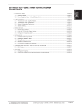
3.1 System Configuration Example
3.2 Hardware Connection Diagram
(1) LAN connection
Connect the LAN cable to the personal computer. For the location of the LAN connector for the
personal computer, refer to the Instruction Manual of the personal computer.
3. System Configuration
Note:
• Be sure to use the hub.
• Execute the LAN cascade connection as shown below.
For 10BASE-T, the cascade connection is executable up to a maximum of 4 stages.
For 100BASE-T, the cascade connection is executable up to a maximum of 2 stages.
Remote
controller
Power
supply unit
Integrated software
TG-2000
HUB
G-50A
G-50A
LAN
Outdoor unit
Indoor unit
[Image drawing]
Power
supply u
nit
Integrated software
TG-2000
HUB
10BASE-T
straight cable
LAN
To G-50A

6
4.1 Flow of Site Adjustment
When the task of site adjustment is subdivided into smaller tasks as shown in the figure below, the
tasks can be broadly grouped into three steps. The benefit of following these three steps when
carrying out the tasks of site adjustment is that if troubles do arise, it will be clear which step caused
the problem. This makes it easier to solve problems and this results in a more efficient execution of
site adjustment tasks.
Carry out site adjustment, by following the step by step instructions shown below.
4.2 Tools for Site Adjustment
You will need the following equipment and reference material in order to easily carry out site adjustment.
<Measurement instruments>
• Tester : to check the wiring and the voltage
<Reference material>
• All necessary drawings of the air conditioning control system
• TG-2000A Instruction Manual (Site Adjustment (this manual), Management)
• Operation Manual for each air conditioner unit and controller
<Other material>
• Floppy disk : used when copying data
• CD-R : used to store generated data and copy it to the site PC.
• Initial setting tool: Personal computer in which this tool is installed
• LAN cable : PAC-YG00FA LAN cable
• Screwdriver kit
• Other usual maintenance tools
Step 1 G-50A test run
Check that the air conditio
ners and controllers
are correctly configured and that the air con-
ditioner works.
Step 2
PC connections and settings
Connect and set up the software and hard
-
ware on the PC with TG-2000A installed.
Check that it is ready for operation.
Step 3 TG-2000A system test run
Check that the TG-2000A man-
machine system can correctly operate air conditioner units of all
the managed systems by issuing TG-2000A commands.
4. Flow of Site Adjustment
* See Chapter 4 in this booklet for details.
*
For the test operation method of the air
conditioner and centralized controller G-
50A,
refer to the relevant installation manuals.
l Check
that only the air conditioner test
operation has been completed before
starting Step 1.
l
LAN
Power
supply unit
Step 1
Step 3
Step 2
Integrated centralized
control software
TG-2000A
HUB
G-50A
Step 1

7
4.3 Step 1: Test operation from centralized controller G-50A
Perform only the test operation of the air-conditioning system of the central controller G-50A.
(1) Preliminary check
Check that the test operation of the air conditioner has been completed.
Check that the central controller G-50A is set to Group and Interlock.
(The initial setting is executable using the initial setting tool or the G-50A.)
(2) Test operation from central controller G-50A
After supplying power to the central controller G-50A and all air conditioners, perform the test
operation from the central controller G-50A, and check the operation state of each unit.
* For the test operation method, refer to the installation manual for the air conditioner or the
central controller G-50A.
4.4 Step 2: Initial setting of integrated centralized control software TG-2000A
(1) Set-up of integrated centralized control software TG-2000A
Make preparations to allow the personal computer to be operative in order to install the integrated
centralized control software TG-2000A. After performing the set-up preparations, set up the
integrated centralized control software TG-2000A.
(2) Check the G-50A IP address and personal computer (which uses the integrated centralized control
software)
Check the G-50A IP address. Check the IP address used for the integrated centralized control
software at the same time. Normally, set the sub-net to "255.255.255.0".
For a LAN dedicated to the G-50A system, it is recommended to set the IP address
within the following range.
Models IP address range
G-50A main unit [192.168.1.1] to [192.168.1.40]
Personal computer for browser [192.168.1.101]to [192.168.1.149]
Personal computer
for integrated centralzed control software
[192.168.1.150]
PLC [192.168.1.151]to [192.168.1.200]
Personal computer of initial setting tool [192.168.1.201]
* To connect to the existing LAN, set the IP address and sub-net mask set by the LAN manager.
(3) LAN connection confirmation
Check that the LAN cable is connected to the G-50A, personal computer (using integrated
software), and hub, and that power is supplied to the hub.
(4) Initial setting of integrated centralized control software
Start the integrated centralized control software TG-2000A to execute the initial setting.
Note:
• For the set-up procedure, refer to Chapter 5.
• For safety, check the installation state/connection before turning the power ON.
Note:
• For the initial setting method of the integrated software, refer to Chapters 6 to 8.
Power
supply unit
Step 1
Integrated centralized
control software
TG-2000A
HUB
G-50A

8
4.5 Step 3: Test operation from integrated centralized control software TG-2000A
Perform the test operation from the integrated centralized control software TG-2000A to check the
operation state and monitor display of the air conditioner.
For the operation procedure, refer to the Instruction Manual (Management).
Note:
• For confirmation in the test operation, use the checklist shown in Chapter 11.
• Perform the normal operation from the integrated centralized control software TG-
2000A to
execute the test operation/confirmation. (The test operation function is not included in the
start/stop function.)

9
5.1 Pre-installation Steps
Preparing for installation
Before installing the TG-2000A application, do the following checks and preparatory steps.
Steps
Action Details How to
1 Check the OS Check the OS Service Pack version.
• Windows XP Professional
• Windows 2000 Professional: SP2
and above
*
If not the correct version,
refer to the attached
documentation, “Installing
• Windows 2000/XP” and
upgrade the OS.
2 Check the memory
Check that there is at least 128 MB of
RAM (256MB or more is
recommended.)
* If necessary, add more
RAM.
3 Check the HDD free
space
Check that there is at least 2GB of free
space on
the C drive. (OS already set
up)
* Refer to the Windows
instruction manual for
more details.
4 Printer settings
Install the printer driver and check that
printing is possible.
*
For details, refer to the
attached instruction
manual.
5 Set the date and time
In the Windows Control Panel, select
“Date and
Time” and set the date, time
and region
*
For details, refer to the
Windows users manual.
6 Screen size and color
settings
At the “display” in the Windows Control
Panel, set
the screen size to 1024 × 768
or larger and the
color to 65536 colors
(High Color (16-bit)) or more.
*
For details, refer to the
Windows users manual.
7 Automatic login
settings
Check that the Auto log-in is set. *2
* For the setting check pro-
cedure, see Appendix 2
Auto Log-in Check Proce-
dure.
8 Network settings Check tha
t the network settings have
been
performed (even if the adapter is
not connected).
*
For details, refer to the
Windows users manual.
*1 Check when using the printer.
*2 Auto log-in sets the automatic start-up without entering the log-in name or password at the OS
start-up.
5.2 TG-2000A Setup
5.2.1 Setup
The following shows the TG-2000A setup disk (CD-ROM) folder configuration and files. However, it
only describes the files to be run.
CD-ROM drive\Setup\Step1\MSDEInst.bat
\Step2\DbSetup.bat
\Step3\SetupTG.exe
[Reference] CD-ROM directory structure
readme.txt : Directory structure and setup precautions of this CD-ROM
\Setup : Set-up folder
\Tool : Air-conditioning charge calculation support tool (chargecalc.xls)
\Manual : Operation Manual
5. Installation
Note:
• The TG-
2000A will not be started automatically after starting (rebooting) the personal computer
when the TG-2000A is set to Auto reboot, unless the Auto log-in is set. When the TG-
2000A is set
to Auto re-boot, be sure to set the Auto log-in.

10
5.2.2 Running TG-2000A Setup (New setup)
The TG-2000A setup is performed in three stages:
Step 1) MSDE setup
Step 2) Database setup
Step 3) TG-2000A setup
Step 1) MSDE setup
Run the “MSDEInst.bat” file in the “\Setup\Step1” folder.
A DOS window will open and the close 2 or 3 minutes
later when the process has finished.
When the installation is completed, restart the
computer.
Step 2) Database setup
Run the “DbSetup.bat” file in the “\Setup\Step2” folder.
A DOS window will open and the close 10 seconds
later when the process has finished.
Step 3) TG-2000A setup
Run the setup program for TG-2000A. Perform the
setup in accordance with the instructions on the
screen.
(1) Starting the setup program
1) Starting SetupTG.exe
Use Windows Start-Run to execute Run SetupTG.exe
in the “\Setup\Step3” folder in the root directory of the
Setup CD.
The setup start confirmation window appears. Read
and check the cautions which appear on the screen.
2) Check the displayed items and click the [Next] button.
If there is no problem with the cautions, click the [Next]
button to continue on to the next screen.
* Click the [Cancel] button to stop the setup.
Note:
• Perform the 3 setup steps sequentially. Otherwise, the TG-2000A will not operate properly.
• Be sure to log-in to Windows, using the Auto log-in name and password before executing the set-up.
(It is necessary to execute the log-in with a log-in name having administrator rights.)
Note:
•
Restart the personal computer after completing the
MSDE set-
up. Otherwise, Step 2 which follows may
not be able to be set up properly.

11
(2) Read the license agreement
1) Read the license agreement and click the [Next] button.
The license agreement screens will be displayed one at
a time. Carefully read all of the agreement and check
that you agree with each item before selecting “It
agrees” and clicking [Next] to continue.
* If you cannot agree with the license agreement,
click the [Cancel] button and stop the installation of
TG-2000A.
(3) Check the installation folder
1) Check the location where the program is to be installed
and click the [Next] button.
Check the location where the program is to be installed.
If the location needs to be changed, set the new
location by clicking the [Browse] button.
After checking the installation location, click the [Next]
button.
* Click the [Cancel] button to stop the installation.
(4) Installation start confirmation
1) Confirm that you want to start the installation and
select the [Next] button.
If the [Next] button is clicked the installation will start.
* Click the [Cancel] button to stop the installation.
(5) TG-2000A setup completion
1) Select [Finish] button
Click [Finish] button on installation screen.
After the installation is completed, restart the computer.
When the installation is completed, the program is
registered in the start menu and automatically run from
the next time the computer is started.
Store the CD is a safe place.
Note:
•
Be sure to restart the personal computer after
installing TG-2000A.

12
5.3 TG-2000A Uninstall
This section describes how to uninstall an installed “MSDE” and “TG-2000A” program.
(1) TG-2000A uninstall
1) Check to see if TG-2000A has ended
Check to see if the TG-2000A program has ended. If
it has not ended, end it.
* For a description of the ending method, see
Chapter 7.
2) Start “Add/Remove Programs”.
Start by clicking Control Panel’s Add/Remove Pro-
grams.
3) Select “TG-2000A”, and click [Change/Remove]
button.
Select “Integrated centralized control software
TG-2000A” from the displayed programs, and click the [Change/Remove] button. Uninstallation of
the TG-2000A program begins.
4) “Add/Remove Programs” ending
When program uninstallation ends, Add/Remove Programs ends.
(2) MSDE uninstall
1) Start the SQL Server Service Manager
Start the “SQL Server Service Manager” by right-clicking the MSDE
icon on the taskbar.
2) Stop all service
To stop all service, make your selection at the Service field and
click the [Stop] button.
3) End the SQL Server Service Manager
The “SQL Server Service Manager” window closes.
4) Close the MSDE icon
Right-click the MSDE icon on the taskbar and select [Exit]. The
MSDE icon is removed from the taskbar.
5) Start “Add/Remove Programs”.
Start by clicking on the Control Panel’s Add/Remove Programs.
6) Choose “MSDE”, and click the [Change/Remove] button.
Select “MSDE“ from the displayed programs, and click the
[Change/Remove] button.
Uninstallation of the MSDE program begins.
7) “Add/Remove Programs” ending
When program uninstallation ends, “Add/Remove Programs” ends.
Note:
• We recommend that you do not delete all the shared files.
• This uninstall cannot delete some folders and files. (Ex: C:\TG-2000)
Note:
• This uninstall cannot delete some folders and files. (Ex: C:\Mssql7)
• When MSDE is used, uninstall is unnecessary.
MSDE icon

13
6.1 Window Elements
The window displayed when the power is turned on and no system settings have been made is called
the Initial window. The Initial window has the following parts.
(The Initial window can be accessed from the menu bar with a password. For details, see section 6.3.)
Click the buttons to display the window associated with that feature. An example is shown below.
Displays the operation contents of the [Next], [Back], [Cancel], and [OK] buttons on each setting screen.
Buttons Operation contents
[OK]
Advances to the setting screen with the confirmation contents on the preparation
screen determined not to have any problems.
Validates the contents set on this display screen to advance to the next setting screen.
[Next] Advances to the next setting screen.
[Back] Invalidates the contents set on this display screen to return to the last screen.
[Cancel] Invalidates the contents set on this display screen to shift to the initial screen.
6. Part Names and Functions
Initial window
Menu bar:
Shows a list of
functions that may be
selected
System setting
group:
Sets the group infor
-
mation, monitor dis-
play, charge calcula
-
tion system, etc.
Maintenance group:
Function to correct the
charge calculation, etc.
Title bar:
Shows the title of the
window
User setting group:
Sets valid/invalid
for the
function, site name, and
password.
Exit button:
Exits the Initial window
and moves to the Manage-
ment window
Message bar:
Shows time, warnings,
and other comments
Equipment state
display:
Displays the system
equipment as error or
normal.
Title bar:
Display the title of
the window.
Message bar:
Display comments
about function dis-
play and operation
Function display -
operation setting
section:
Used to display/set the set-
ting contents.
Next, Back, Cancel,
and OK buttons:
Choose to end, return,
next,
or cancel the setting of func-
tion display and operation
settings
System Configuration Options Control Window

14
6.2 Basic Mouse Operation
First, use of the mouse as a pointing device will be explained. If a device other than a mouse is being
used, consult with the manual for that device.
The following is a list of terms used in describing mouse operations.
Click : This refers to pressing and releasing the button one time.
To use this function, click the button
Double Click: This refers to pressing and releasing the button twice in quick succession.
Drag : This refers to moving the mouse pointer on top of an object on the screen, pressing
and holding down the button to select the object, then, while holding the button down,
moving the mouse pointer, and the object, to a different location.
Keyboard : Primarily used when entering password, characters, or numerics.
6.3 Accessing Functions and M oving between Windows
The functions of the TG-2000A can be divided into two general categories.
1) Functions that monitor air conditioner operation status and control functions……Initial window
2) Operation and system initialization and charge data maintenance functions (functions used to
accomplish functions in 1) above)……Control window(Management screen)
This section deals mostly with functions in category 2).
(1) Shift from the initial window to the control window
The following shows the procedure to shift from the initial window to the control window. Shift the
screen to the control window after completing the initial setting shown in Chapter 8.
[Procedure]
1) Select [Finish] button.
Click the [Finish] button located on the lower right on
the initial screen. With the above step, the
confirmation screen (asking whether or not to trans-
mit the setting contents to the G-50A) is displayed.
2) Select [OK] button.
Click the [OK] button to transmit the initial setting
contents to the G-50A.
The start-up display screen is displayed after the
screen has been shifted to the control window. The
system information set or changed is transmitted to
each G-50A to enter upon the start-up processing.
It takes approximately 10 to 20 minutes to start-up.
* Note that the setting contents will not be trans-
mitted to the G-50A when the [Cancel] button is
clicked. If it is used when only the maintenance
group function is operated, it is possible to shorten
the time required until the control window
resumes.
(2) Shift from the control window to the initial
window
The control window shifts to the initial window when
the initial setting contents are changed or when the
charge calculation maintenance is performed.
[Procedure]
1) Select [Configuration] and then [System set] in the
menu bar.
Click the [Configuration] in the menu bar on the
control window to select the [System set]. The
password confirmation screen is displayed.
Screen of confirmation for
transmitting set contents
Start-up display screen
Display screen of Shift to setting screen

15
2) Enter the password
Enter the word “*****” in the password verification box, then
click the [OK] button. Doing so returns you to the initial
window.
There are two kinds of passwords.
Initialization password: All the items in the initial
window can be used. The
initial password is “SYSTEM”.
Maintenance password: The initial window maintenance group and personal password can be
changed. The initial password is “Maintenance”.
Maintenance Tip
•
Manage the password to prevent unauthorized personnel from accessing the system. The
password can be changed.
Password input screen

16
<TG-2000A screen order 1>
Power On + Start
TG-2000A
No system data
System data
Exit TG-2000A, shut
down the OS, and
turn
the power off
Select [File]-[End
]
button
Select [Exit
]
button
* Range described in this manual
[User setup group]
[System setup group]
Password input
Return to Initial window
Control window(Management screen)
(see separate management manual)

17
Wizard name Primary settings contained in the activated window
User Set-up Set TG-2000A functions
Wizard name Primary settings contained in the activated window
Site Name Set-up Set the product name (site name)
Wizard name Primary settings contained in the activated window
Password change Changes the password to the two types of Initial window
Wizard name Primary settings contained in the activated window
Preparation for the G-50A
connection setting
Checks the step/caution display for the G-50A connection
setting.
Number of G-50A units setting Sets the number of G-50A units.
G-50A IP address setting Sets the IP address for each G-50A.
It is possible to display the optional functions of the G-50A.
Wizard name Primary settings contained in the activated window
Preparation for System
configurations setup
Verifies the order of system configuration settings and displays
warnings
Collecting G-50A data Collects the setting information for the G-50A during the initial
setting.
Unit configurations setup Sets the unit configurations in G-50A.
System structure of refrigerant
system
Set refrigerant connections.
Function of each group Set indoor unit and ventilation groups.
Ventilation unit grouping Set ventilators and indoor unit groupings.
Wizard name Primary settings contained in the activated window
Preparation for Monitoring screen
set-up
Verifies the order of monitoring screen settings and displays
warnings
Set-up of model name Sets the model name of unit
Set-up of the number of floors, and
floor name
Sets the number of floors and floor name.
Creation of a plane view Create a floor plane to be used in the floor window of the Management
screen(control window)
Set-up of floor name and G-50A Set floor and G-50A assignment
Set-up of icon arrange and name Layout icons on the floor plane, and set names
Set-up of block
Set groups in blocks
Wizard name Primary settings contained in the activated window
Time set-up Sets the current time.
Wizard name Primary settings contained in the activated window
Preparation for WHM set-up Check the WHM setting order and notes display.
Watt hour meter setting Sets the watt hour meter connection port and watt hour meter
address.
Set-up for the name and the
maximum count value of WHM
Sets the WHM name, installation location, and maximum
integrated value.
/