Page is loading ...

OPERATION AND PARTS MANUAL
Revision #6 (10/27/11)
MODELS
MQD2H
MQD3H
DIAPHRAGM PUMPS
(Honda
GX120K1QX2
Gasoline Engine)
THIS MANUAL MUST ACCOMPANY THE EQUIPMENT AT ALL TIMES.
To find the latest revision of this
publication, visit our website at:
www.multiquip.com

PAGE 2 — MQD2H/3H DIAPHRAGM PUMPS — OPERATION AND PARTS MANUAL — REV. #6 (10/27/11)
PROPOSITION 65 WARNING

MQD2H/3H DIAPHRAGM PUMPS — OPERATION AND PARTS MANUAL — REV. #6 (10/27/11) — PAGE 3
NOTES

PAGE 4 — MQD2H/3H DIAPHRAGM PUMPS — OPERATION AND PARTS MANUAL — REV. #6 (10/27/11)
MQ-D2H/D3H Gasoline
Powered Diaphragm
Pumps
Proposition 65 Warning ............................................. 2
Table of Contents ...................................................... 4
Parts Ordering Procedures ....................................... 5
Safety Information .................................................. 6-9
Specifications ...........................................................10
Dimensions ..............................................................11
General Information .................................................12
Components.............................................................13
Basic Engine ............................................................ 14
Inspection .................................................................15
Set-up ................................................................ 16-17
Operation ........................................................... 18-19
Maintenance ...................................................... 20-25
Preparation for Long-Term Storage .........................26
Troubleshooting ................................................. 27-29
Explanation Of Code In Remarks Column ...............30
Suggested Spare Parts ............................................ 31
HONDA GX120K1QX2 Engine
Air Cleaner Assembly......................................... 46-47
Camshaft Assembly ........................................... 48-49
Carburetor Assembly ......................................... 50-51
Control Assembly ............................................... 52-53
Crankcase Cover Assembly ............................... 54-55
Crankshaft Assembly ......................................... 56-57
Cylinder Barrel Assembly ................................... 58-59
Cylinder Head Assembly .................................... 60-61
Fan Cover Assembly .......................................... 62-63
Flywheel Assembly ............................................ 64-65
Fuel Tank Assembly ........................................... 66-67
Ignition Coil Assembly ........................................ 68-69
Muffler Assembly ............................................... 70-71
Piston Assembly ................................................. 72-73
Recoil Starter Assembly..................................... 74-75
Gasket Kit Assembly .......................................... 76-77
Labels ................................................................ 78-79
Terms and Condition Of Sale
— Parts .................... 80
Component Drawings
Nameplate and Decals Assy. ............................. 32-33
Waterbox and Flap Valve Assy. (2-inch) ............. 34-35
Pump Assy. (2-inch) ........................................... 36-37
Handle, Engine and Wheel Assy. (2-inch) .......... 38-39
Waterbox and Flat Valve Assy. (3-inch) .............. 40-41
Pump Assy. (3-inch) ........................................... 42-43
Handle, Engine and Wheel Assy. (3-inch) .......... 44-45
TABLE OF CONTENTS
Specification and part number are subject to
change without notice.
NOTICE

MQD2H/3H DIAPHRAGM PUMPS — OPERATION AND PARTS MANUAL — REV. #6 (10/27/11) — PAGE 5
www.multiquip.com
Ordering parts has never been easier!
Choose from three easy options:
WE ACCEPT ALL MAJOR CREDIT CARDS!
When ordering parts, please supply:
❒ Dealer Account Number
❒ Dealer Name and Address
❒ Shipping Address (if different than billing address)
❒ Return Fax Number
❒ Applicable Model Number
❒ Quantity, Part Number and Description of Each Part
❒ Specify Preferred Method of Shipment:
✓ UPS/Fed Ex ✓ DHL
■ Priority One ✓ Tr u c k
■ Ground
■ Next Day
■ Second/Third Day
If you have an MQ Account, to obtain a Username
and Password, E-mail us at: parts@multiquip.
com.
To obtain an MQ Account, contact you
r
District Sales Manager for more information.
Order via Internet (Dealers Only):
Order parts on-line using Multiquip’s SmartEquip website!
■ View Parts Diagrams
■ Order Parts
■ Print Specification Information
Note: Discounts Are Subject To Change
Goto www.multiquip.com and click on
Order Parts
to log in and save!
Use the internet and qualify for a 5% Discount
on Standard orders for all orders which include
complete part numbers.*
Order via Fax (Dealers Only):
All customers are welcome to order parts via Fax.
Domestic (US) Customers dial:
1-800-6-PARTS-7 (800-672-7877)
Fax your order in and qualify for a 2% Discount
on Standard orders for all orders which include
complete part numbers.*
Order via Phone:
Domestic (US) Dealers Call:
1-800-427-1244
Best Deal!
International Customers should contact
their local Multiquip Representatives for
Parts Ordering information.
Non-Dealer Customers:
Contact your local Multiquip Dealer for
parts or call 800-427-1244 for help in
locating a dealer near you.
Note: Discounts Are Subject To Change
Effective:
January 1
st
, 2006
NOTICE
All orders are treated as Standard Orders and will
ship the same day if received prior to 3PM PST.
PARTS ORDERING PROCEDURES

PAGE 6 — MQD2H/3H DIAPHRAGM PUMPS — OPERATION AND PARTS MANUAL — REV. #6 (10/27/11)
Do not operate or service the equipment before reading
the entire manual. Safety precautions should be followed
at all times when operating this equipment.
Failure to read and understand the safety
messages and operating instructions could
result in injury to yourself and others.
SAFETY MESSAGES
The four safety messages shown below will inform you
about potential hazards that could injure you or others. The
safety messages specifically address the level of exposure
to the operator and are preceded by one of four words:
DANGER, WARNING, CAUTION or NOTICE.
SAFETY SYMBOLS
DANGER
Indicates a hazardous situation which, if not avoided,
WILL result in DEATH or SERIOUS INJURY.
WARNING
Indicates a hazardous situation which, if not avoided,
COULD result in DEATH or SERIOUS INJURY.
CAUTION
Indicates a hazardous situation which, if not avoided,
COULD result in MINOR or MODERATE INJURY.
NOTICE
Addresses practices not related to personal injury.
Potential hazards associated with the operation of this
equipment will be referenced with hazard symbols which
may appear throughout this manual in conjunction with
safety messages.
Rotating parts hazards
Symbol Safety Hazard
Electric shock hazards
SAFETY INFORMATION

MQD2H/3H DIAPHRAGM PUMPS — OPERATION AND PARTS MANUAL — REV. #6 (10/27/11) — PAGE 7
GENERAL SAFETY
CAUTION
NEVER operate this equipment without proper protective
clothing, shatterproof glasses, respiratory protection,
hearing protection, steel-toed boots and other protective
devices required by the job or city and state regulations.
Avoid wearing jewelry or loose fitting clothes that may
snag on the controls or moving parts as this can cause
serious injury.
NEVER operate this equipment when not
feeling well due to fatigue, illness or when
under medication.
NEVER operate this equipment under the
influence of drugs or alcohol.
ALWAYS clear the work area of any debris, tools, etc.
that would constitute a hazard while the equipment is
in operation.
No one other than the operator is to be in the working
area when the equipment is in operation.
DO NOT use the equipment for any purpose other than
its intended purposes or applications.
NOTICE
This equipment should only be operated by trained and
qualified personnel 18 years of age and older.
Whenever necessary, replace nameplate, operation and
safety decals when they become difficult read.
Manufacturer does not assume responsibility for any
accident due to equipment modifications. Unauthorized
equipment modification will void all warranties.
NEVER use accessories or attachments that are not
recommended by Multiquip for this equipment. Damage
to the equipment and/or injury to user may result.
ALWAYS know the location of the nearest
fire extinguisher.
ALWAYS know the location of the nearest
first aid kit.
ALWAYS know the location of the nearest phone or keep
a phone on the job site. Also, know the phone numbers
of the nearest ambulance, doctor and fire department.
This information will be invaluable in the case of an
emergency.
SAFETY INFORMATION

PAGE 8 — MQD2H/3H DIAPHRAGM PUMPS — OPERATION AND PARTS MANUAL — REV. #6 (10/27/11)
SAFETY INFORMATION
PUMP SAFETY
DANGER
NEVER operate the equipment in an explosive
atmosphere or near combustible materials. An
explosion or fire could result causing severe
bodily harm or even death.
NEVER use pump for swimming pool dewatering applications.
This can result in electrical shock or electrocution.
WARNING
Accidental starting can cause severe injury
or death. ALWAYS place the ON/OFF
switch in the OFF position.
DO NOT place hands or fingers inside
pump when pump is running.
NEVER disconnect any emergency or
safety devices. These devices are intended for operator
safety. Disconnection of these devices can cause severe
injury, bodily harm or even death. Disconnection of any
of these devices will void all warranties.
CAUTION
DO NOT restrict the flow of the discharge hose as it may
cause overheating.
Be careful of discharge whipping under pressure.
NOTICE
ALWAYS place the pump in an upright position on a
platform before using. The platform will prevent the pump
frowm burrowing itself on soft sand or mud.
NEVER operate pump on its side.
DO NOT allow up to freeze in water.
NEVER leave an open pump chamber unattended.
ALWAYS keep the machine in proper running condition.
DO NOT attempt to thaw-out a frozen pump by using
a torch or other source of flame. Application of heat in
this manner may heat the oil in the seal cavity above the
critical point, causing pump damage.
DO NOT pump water greater than 104º F.
DO NOT pump liquids containing acid or alkali.
ALWAYS check strainer before pumping. Make sure
strainer is not clogged. Remove any large objects, dirt
or debris from the strainer to prevent clogging.
ALWAYS use a large basket strainer when pumping
water that contains large debris.
ALWAYS flush pump (clean) after use when pumping
water concentrated with heavy debris. It is very important
to always flush the pump before turning it off to prevent
clogging.
Fix damage to machine and replace any broken parts
immediately.
ALWAYS store equipment properly when it is not being
used. Equipment should be stored in a clean, dry location
out of the reach of children and unauthorized personnel.
NEVER lubricate components or attempt service on a
running machine.
ALWAYS allow the machine a proper amount of time to
cool before servicing.
Keep machine in proper running condition.
ELECTRICAL SAFETY
DANGER
The electrical voltage required to operate
pump can cause severe injury or even death
through physical contact with live circuits.
ALWAYS disconnect electrical power from
pump before performing maintenance on
pump.
NOTICE
ALWAYS
make certain that the voltage supplied to the
pump is correct. Always read the pump’s nameplate to
determine what the power requirements are.

MQD2H/3H DIAPHRAGM PUMPS — OPERATION AND PARTS MANUAL — REV. #6 (10/27/11) — PAGE 9
SAFETY INFORMATION
Power Cord/Cable Safety
DANGER
NEVER let power cords or cables lay in water.
NEVER use damaged or worn cables or cords. Inspect
for cuts in the insulation.
NEVER grab or touch a live power
cord or cable with wet hands. The
possibility exists of electrical shock,
electrocution or death.
Make sure power cables are securely connected to the
motor's output receptacles. Incorrect connections may
cause electrical shock and damage to the motor.
WARNING
NEVER attempt to use the power cord as a lifting or
lowering device for the pump.
NOTICE
ALWAYS make certain that proper power or extension
cord has been selected for the job. See Cable Selection
Chart in this manual.
Grounding Safety
DANGER
ALWAYS make sure pump is grounded.
ALWAYS make sure that electrical circuits are properly
grounded to a suitable earth ground (ground rod) per
the National Electrical Code (NEC) and local codes
before operating generator. Severe injury or death by
electrocution can result from operating an ungrounded
motor.
NEVER use gas piping as an electrical ground.
LIFTING SAFETY
CAUTION
When raising or lowering of the pump is required, always
attach an adequate rope or lifting device to the correct
lifting point (handle) on the pump.
NOTICE
DO NOT lift machine to unnecessary heights.
NEVER lift the equipment while the engine is running.
TRANSPORTING SAFETY
NOTICE
ALWAYS shutdown pump before transporting.
ALWAYS tie down equipment during transport by
securing the equipment with rope.
ENVIRONMENTAL SAFETY
NOTICE
Dispose of hazardous waste properly.
Examples of potentially hazardous waste
are used motor oil, fuel and fuel filters.
DO NOT use food or plastic containers to dispose of
hazardous waste.
DO NOT pour waste, oil or fuel directly onto the ground,
down a drain or into any water source.

PAGE 10 — MQD2H/3H DIAPHRAGM PUMPS — OPERATION AND PARTS MANUAL — REV. #6 (10/27/11)
Table 2. Specifications (Engine)
Engine
Model HONDA GX120K1QX2
Ty pe
Air-cooled 4 stroke, Single
Cylinder, OHV, Horizontal
Shaft Gasoline Engine
Bore X Stroke
2.4 in. x 1.7 in.
(60 mm x 42 mm)
Displacement 119 cc (7.2 cu-in)
Max Output 4.0 H.P./2,750 R.P.M.
Fuel Tank Capacity 0.66 US gal. (2.5 liters)
Fuel
Unleaded Automobile
Gasoline
Lube Oil Capacity .60 liters (0.63 qts)
Speed Control
Method
Centrifugal Fly-weight Type
Starting Method Recoil Start
Dimension
(L x W x H)
11.7 x 13.4 x 12.5 in.
(297 x 341 x 318 mm)
Dry
Net Weight
28.7 lbs (13 Kg.)
)pmuP(snoitacificepS.1elbaT
pmuP
epyTpmuPmgarhpaiDH2D-QMpmuPmgarhpaiDH3D-QM
egrahcsiD&noitcuS
eziS
).mm8.05(.ni00.2).mm2.67(.ni00.3
gnipmuPmumixaM
yticapaC
ruoh/snollag000,3
)ruoh/sretil043,11(
ruoh/snollag004,5
)ruoh/sretil654,02(
retemaiDsdiloS.xaM)mm1.83(.ni2/1-1)mm572.14(ni8/5-1
tfiLxaM)sretem29.7(.tf62)sretem29.7(.tf62
daeH.xaM)sretem26.7(.tf52)sretem26.7(.tf52
thgieWteNyrD
).gK36(.sbl041
).gK27(.sbl061
SPECIFICATIONS

MQD2H/3H DIAPHRAGM PUMPS — OPERATION AND PARTS MANUAL — REV. #6 (10/27/11) — PAGE 11
MQ-D2H/D3H — DIMENSIONS (PUMP)
snoisnemiD.3elbaT
LEDOM
A
HTGNEL
B
THGIEH
C
HTDIW
D
EGRAHCSID
E
NOITCUS
H2D-QM
.ni93
).mc60.99(
.ni35.72
).mc39.96(
.ni86.52
).mc32.56(
.
ni43.7
).mc46.81(
.ni26.5
).mc72.41(
H3D-QM
.ni5.14
).mc14.501(
.ni22
).mc88.55(
.ni03
).mc2.67(
.ni2.6
).mc57.51
(
.ni3.6
).mc61(
Figure 1. MQ-D2H/D3H Pump Dimensions
DIMENSIONS

PAGE 12 — MQD2H/3H DIAPHRAGM PUMPS — OPERATION AND PARTS MANUAL — REV. #6 (10/27/11)
MQ-D2H/D3H — GENERAL INFORMATION
APPLICATION
The
MQD2H
and
MQD3H diaphragm
pumps are designed to
be used for de-watering applications. The suction and discharge
ports on the
MQD2H
use a 2-inch diameter opening, which allows
the pump to pump at rate of approximately 3,000 gallons/hour
(gph) or 11,340 liters/hour (lph). The suction and discharge ports
on the
MQD3H
use a 3-inch diameter opening, which allows the
pump to pump at rate of approximately 5,400 gallons/hour (gph)
or 20,456 liters/hour (lph).
Diaphragm pumps use a positive displacement design rather
than centrifugal force to move water through the casing. This
means the pump will deliver a specific amount of flow per stroke,
revolution or cycle. These pumps are commonly referred to as
mud hogs, mud hens and mud suckers. Their names reflect their
popularity for use in applications where shallow depths and slurry
water render centrifugal pumps ineffective.
Power Plant
These diaphragm pumps are powered by a 4.0 horsepower air
cooled, 4-stroke, single cylinder
HONDA GX120
gasoline engine
that incorporates a low “
Oil Alert Feature
” . The drive shaft of the
engine is coupled to an offset connecting rod that is coupled to a
flexible diaphragm. The connecting rod alternately raises
(expands) and lowers (contracts) the diaphragm at a rate of 60
cycles per minute at maximum engine RPM (2,750).
Oil Alert Feature
In the event of
low oil
or
no oil
, the HONDA GX120 engine has
a built-in oil alarm engine shut-down feature. In the event the oil
level is low the engine will automatically shut-down.
Suction Lift
This pump is intended to be used for dewatering applications
and is capable of suction lifts up to 25 feet at sea level. For
optimal suction lift performance keep the suction hose or line as
short as possible. In general always place the pump as close to
the water as possible.
Pump Support
The pump should always be placed on
solid stationary ground
in a level position.
NEVER place the pump on
soft soil
. The suction hose or pipe
connection should always be checked for tightness and leaks. A
small suction leak in the hose or fittings could prevent the pump
from priming.
Elevation
Higher elevations will effect the performance of the pump. Due to
less atmospheric pressure at higher altitudes, pumps DO NOT
have the priming ability that they have at sea level. This is due to
the “thinner air” or lack of oxygen at higher altitudes.
A general rule of thumb is that for every 1,000 feet of elevation
above sea level a pump will lose one foot of priming ability.
For example, in Flagstaff, Arizona where the elevation is
approximately 7,000 feet, the pump would have a suction lift of
only 18 feet rather than the 25 feet at sea level. Table 3 shows
suction lift at various elevations.
Table 4 shows percentage drops in performance as elevation
increases.
suoiraVtassoLecnamrofreP.5elbaT
snoitavelE
edutitlA
sreteM(teeF
wolFegrahcsiDdaeHegrahcsiD
leveLaeS%001%001
)016(000,2%79%59
)912,1(000,4%59%19
)928,1(000,6%3
9%78
)834,2(000,8%19%38
)840,3(000,01%88%87
snoitavelEsuoiraVtatfiLnoitcuS.4elbaT
edutitlA
)sreteM(teeF
)sreteM(teeFnitfiLnoitcuS
leveLaeS)840.3(0.01)275.4(0.51)690.6(0.02)026.7(0.52
)016(000
,2)086.2(08.8)320.4(2.31)463.5(6.71)507.6(0.22
)912,1(000,4)773.2(08.7)665.3(7.11)457.4(6.51)349.5(5.91
)928,1(
000,6)301.2(09.6)961.3(4.01)602.4(8.31)372.5(3.71
)834,2(000,8)988.1(02.6)438.2(03.9)977.3(4.21)427.4(5.51
)840
,3(000,01)737.1(07.5)126.2(06.8)474.3(4.11)853.4(3.41
GENERAL INFORMATION

MQD2H/3H DIAPHRAGM PUMPS — OPERATION AND PARTS MANUAL — REV. #6 (10/27/11) — PAGE 13
Figure 2 shows a typical application using the MQD2H or MQD3H diaphragm pump. Please note that this pump is intended for the
removal of clean water and water containing some debris and solids. Maximum size of solids for the MQD2H should not exceed 1-
1/2 inches (38.1 mm) in diameter, and maximum size of solids for the MQD3H should not exceed 1-5/8 inches (41.275) in diameter.
DO NOT set strainer on bottom of water bed. Placing the strainer above the water bed will prevent the pump from drawing in
excessive amounts of sand and foreign debris.
1. Pump – The Multiquip Models MQD2H and MQD3H are
2-inch and 3-inch diaphragm pumps respectively and are
used in general de-watering applications. Typical
dewatering applications consist of cleaning out cesspools
and septic tanks, draining slow seepage from small
excavations, trenches and construction sites, or pumping
out industrial waste.
2. Priming Plug/Suction Priming Chamber – Fill with clean
water to assist with faster priming times.
3. Discharge Port – Connect either a 2-inch or 3-inch
discharge hose to this port depending on pump model.
4. NPT Connection – Used to secure the hose to the inlet
and outlet ports on the pump.
5. Discharge Hose – Connect a flexible rubber hose to the
discharge port on the pump. Make sure that the hose lays
flat and is not kinked. Use only recommended type discharge
hose. Contact Multiquip parts department for ordering
information.
Figure 2. MQ-D2H/D3H Pump Application
MQ-D2H/D3H — PUMP COMPONENTS
6. Suction Port – Connect either a 2-inch or 3-inch inlet
hose to this port depending on pump model.
7. Suction Hose – Connect a flexible rubber hose to the
suction port on the pump. Make sure that the hose lays flat
and is not kinked. Use only recommended type suction hose.
Contact Multiquip parts department for ordering information.
8. Strainer – Always attach a strainer to bottom side of the
suction hose to prevent large objects and debris from
entering the pump. Strainer should be positioned so that it
will remain completely under water.
9. Transmission Oil Fill Plug – Remove this plug to add
SAE 80/90 EP (API GL-5) gear oil to the transmission.
Transmission oil capacity is 22 ounces (651 ml.).
10. Connecting Rod Grease Access Hole – Grease
connecting rod bearing through this access hole. Grease
connecting rod bearing every 25 hours of operation.
NOTE
Contact your nearest Multiquip
dealer for quick disconnect hoses
and fittings.
COMPONENTS

PAGE 14 — MQD2H/3H DIAPHRAGM PUMPS — OPERATION AND PARTS MANUAL — REV. #6 (10/27/11)
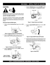
Figure 3. Engine Controls and
Components
INITIAL SERVICING
The engine (Figure 3) must be checked for proper lubrication and
filled with fuel prior to operation. Refer to the Honda manufacturers
engine manual for instructions and details for operation and
servicing.
1. Fuel Filler Cap – Remove this cap to add unleaded
gasoline to the fuel tank. Make sure cap is tightened
securely. DO NOT over fill.
Explosive FuelExplosive Fuel
Explosive FuelExplosive Fuel
Explosive Fuel
6. Choke Lever – Used in the starting of a cold engine, or in
cold weather conditions. The choke enriches the fuel
mixture.
7. Air Cleaner – Prevents dirt and other debris from entering
the fuel system. Remove wing-nut on top of air filter
cannister to gain access to filter element.
8. Spark Plug – Provides spark to the ignition system. Set
spark plug gap to 0.6 - 0.7 mm (0.028 - 0.031 inch) Clean
spark plug once a week.
9. Muffler – Used to reduce noise and emissions.
Operating the engine without an air
filter, with a damaged air filter, or a
filter in need of replacement will
allow dirt to enter the engine,
causing rapid engine wear.
2. Throttle Lever – Used to adjust engine RPM speed (lever
advanced forward
SLOW
, lever back toward operator
FAST
).
3. Engine ON/OFF Switch – ON position permits engine
starting, OFF position stops engine operations.
4. Recoil Starter (pull rope) – Manual-starting method. Pull
the starter grip until resistance is felt, then pull briskly and
smoothly.
5. Fuel Valve Lever – OPEN to let fuel flow, CLOSE to stop
the flow of fuel.
NOTE
Adding fuel to the tank should be done only
when the engine is stopped and has had an
opportunity to cool down. In the event of a fuel
spill, DO NOT attempt to start the engine until
the fuel residue has been completely wiped up,
and the area surrounding the engine is dry.
DANGER - Explosive Fuel
Engine components can generate extreme
heat. To prevent burns, DO NOT touch these
areas while the engine is running or
immediately after operating. NEVER operate
the engine with the muffler removed.
CAUTION - Burn Hazard
10. Fuel Tank – Holds unleaded gasoline. For additional
information refer to engine owner's manual.
BASIC ENGINE

MQD2H/3H DIAPHRAGM PUMPS — OPERATION AND PARTS MANUAL — REV. #6 (10/27/11) — PAGE 15
Figure 4. Engine Oil Dipstick (Removal)
Figure 5. Engine Oil Dipstick (Oil Level)
1. Clean the pump, removing dirt and dust, particularly the
engine cooling air inlet, carburetor and air cleaner.
2. Check the air filter for dirt and dust. If air filter is dirty, replace
air filter with a new one as required.
3. Check carburetor for external dirt and dust. Clean with dry
compressed air.
4. Check fastening nuts and bolts for tightness.
Engine Oil Check
1. To check the engine oil level, place the pump on secure
level ground with the engine stopped.
2. Remove the filler dipstick from the engine oil filler hole
(Figure 4) and wipe clean.
Fuel Check
1. Remove the gasoline cap located on top of fuel tank.
2. Visually inspect to see if the fuel level is low. If fuel is low,
replenish with unleaded fuel.
3. When refueling, be sure to use a strainer for filtration. DO
NOT top-off fuel. Wipe up any spilled fuel
immediately!
epyTliO.6elbaT
nosaeS erutarepmeT epyTliO
remmuS rehgiHroC°52 03-W01EAS
llaF/gnirpS C°01~C°52 02/03-W01EAS
retniW rewoLroC°0 01-W01EAS
CAUTION - Read Manual
Please read the entire maintenance section
in this manual before servicing the pump. In
addition for operator safety, please read all
safey messages at the begining of the
manual
Inspection
3. Insert and remove the dipstick without screwing it into the filler
neck. Check the oil level shown on the dipstick.
4. If the oil level is low (Figure 5), fill to the edge of the oil filler
hole with the recommended oil type (Table 5). Maximum oil
capacity is .63 quarts (.60 liters).
Motor fuels are highly flammable and can be
dangerous if mishandled. DO NOT smoke
while refueling.
Adding fuel to the tank
should be done only when the engine is
stopped and has had an opportunity to cool
down. DO NOT attempt to refuel the pump if the engine is
hot!
or
running
In the event of any spilled fuel, wipe up
immediately.
DO NOT attempt to start the engine until the
fuel residue has been completely wiped up, and the area
surrounding the engine is dry.
DANGER - Explosive Fuel
INSPECTION

PAGE 16 — MQD2H/3H DIAPHRAGM PUMPS — OPERATION AND PARTS MANUAL — REV. #6 (10/27/11)
Before Starting
1. Read safety instructions at the
beginning of manual.
2. Place pump as near to water as
possible, on a firm flat, level surface.
NOTE
Suction and discharge hoses are
available from Multiquip. Contact
your nearest dealer for more
information.
4. The discharge hose is usually a
collapsible
(thin-walled)
hose, however if a thin-walled discharge hose is not avail-
able, a rigid suction hose can be substituted in its place.
5. Make sure the
suction strainer
(Figure 2) is clean and
securely attached to the water end of the suction hose. The
strainer is designed to protect the pump by preventing large
objects from being pulled into the pump.
Before Starting:
DO NOT open
fill cap
if pump is hot! Water inside may
be under pressure.
WARNING - Fill Cap
Hoses and Clamps
1. Check that all hoses are
securely
attached to the pump.
Make certain suction hose (Figure 2) does not have any air
leakage. Use teflon tape or pipe dope on NPT threads.
2. Remember suction hoses must be
rigid
enough not to
collapse when the pump is in operation.
3.
Check that
the
discharge
hose (Figure 2) is not restricted.
Place hose so that it lays as straight as it is possible on the
ground. Remove any twists or sharp bends from hose which
may block the flow of water.
CAUTION - General Safety Precautions
ALWAYS wear approved eye and hearing
protection before operating the pump.
NEVER operate the pump in a confined
area or enclosed area structure that does
not provide ample
free flow of air
.
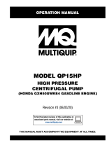
Handle Installation
The MQ-D2H/D3H diaphragm pumps are completely
assembled except for the steering handle. Attach the steering
handle to the pump base as shown in Figure 6.
PUMP BASE
WASHER
BOLT
HANDLE
GEAR
BOX
Figure 6. Handle Installation
CAUTION - Transmission Fluid
Transmission fluid needs to be added prior to operation.
SETUP

MQD2H/3H DIAPHRAGM PUMPS — OPERATION AND PARTS MANUAL — REV. #6 (10/27/11) — PAGE 17
Gear Reduction Oil (Transmission)
1. Remove the transmission oil level plug (Figure 7). If oil
begins to seep out as the plug is being removed, then it
can be assumed that the transmission oil is at the proper
operating level.
2. If oil does not seep out as the oil level plug is being removed,
then remove the transmission oil fill plug and fill with SAE
80/90
EP (API GL-5) gear oil
to the proper operating level.
Transmission oil capacity is capacity is 22 ounces (651 ml).
Connecting Rod Bearing Lubrication
1. Grease connecting rod bearing thru the access
hole (Figure 8) every 25 hours of operation.
2. Use only
premium lithium based grease
, conforming to
NLG1 Grade #2 consistency.
Figure 7. Transmission Oil Level
Figure 8. Connecting Rod Bearing Lubrication
Helpful Hints
The capacity of this diaphragm pump will vary greatly depending on
the height of the suction lift and length of the discharge hose. A
discharge hose which is too small, long or high will cause the
following:
■
Excessive bulging of diaphragm on the down stroke.
■
Valves closing with a loud snap.
■
Rough operation.
■
Engine overloads and slow downs.
■
Reduced efficiency.
NOTE
Diaphragm pumps will handle fluids
containing considerable solids (see
Table 1 for maximum solids diameter),
however, if the mixture is too heavy to
be pumped, water must be added until
the mixture becomes sufficently fluid for
pumping.
This pump uses a water-cooled
mechanical
seal
to prevent water
from seeping into the engine. The
passage of water through the pump
casing lubricates the seal and
prevents it from overheating.
CAUTION - Strainer
The strainer should be positioned so it will remain completely
under water
. Running the pump with the strainer above
water for long periods can damage the pump.
DO NOT pump flammable fluids, corrosive chemicals or fluids
containing toxic substances. These fluids can create potentially
dangerous health and environmental hazards. Contact local
authorities for assistance.
CAUTION - Flammable Fluids
NOTE
SETUP

PAGE 18 — MQD2H/3H DIAPHRAGM PUMPS — OPERATION AND PARTS MANUAL — REV. #6 (10/27/11)
6. Grasp the starter grip (Figure 14) and slowly pull it out. The
resistance becomes the hardest at a certain position, corre-
sponding to the compression point. Pull the starter grip briskly
and smoothly for starting.
Figure 14. Starter Grip
MQ-D2H/D3H — OPERATION
Starting the Engine (
HONDA
engine)
1. Place the engine
fuel valve lever
(Figure 9) to the "ON"
position.
2. Move the
throttle lever
(Figure 10) away from the slow
position, about 1/3 of the way toward the fast position.
Figure 9. Engine Fuel Valve Lever (ON Position)
Figure 10. Throttle Lever (1/3 Start Position)
3. Place the
choke lever
(Figure 11) in the "CLOSED " position
if starting a
cold
engine.
4. Place the
choke lever
(Figure 12) in the "OPEN " position
if starting a
warm engine
or the
temperature is warm.
Figure 11. Engine Choke Lever (CLOSED)
Figure 12. Engine Choke Lever (Open)
5. Place the
engine ON/OFF switch
(Figure 13) in the "ON "
position.
Figure 13. Engine ON/OFF Switch (ON Position)
This section is intended to assist the operator with the
initial
start-up
of the trash pump. It is extremely important that this
section be read carefully before attempting to use the pump in
the field.
DO NOT attempt to operate the pump until the
Safety, General Information and Inspection
sections of this manual have been
read and
thoroughly understood
.
CAUTION - Read Manual
OPERATION

MQD2H/3H DIAPHRAGM PUMPS — OPERATION AND PARTS MANUAL — REV. #6 (10/27/11) — PAGE 19
MQ-D2H/D3H —OPERATION
8. Before the pump is placed into operation, run the engine for
several minutes. Check for fuel leaks, and noises that would
associate with a lose component.
9.
To begin pumping, place the throttle lever (Figure 16) in the
"RUN" position.
Figure 15. Choke Lever (Open)
Figure 16. Throttle Lever (Run)
Stopping The Engine
Normal Shutdown
1. Move the throttle lever to the IDLE position (Figure 17) and
run the engine for three minutes at low speed.
Figure 17. Throttle Lever (Idle)
2. After the engine
cools
, turn the engine ON/OFF switch to the
“OFF” position (Figure 18).
3. Place the
fuel shut-off lever
(Figure 19) in the ”OFF”
position.
Figure 18. Engine ON/OFF Switch (OFF)
Figure 19. Fuel Valve Lever (OFF)
Emergency Showdown
1. Move the throttle lever quickly to the
“
IDLE
”
position, and
place the engine ON/OFF switch in the “OFF” position.
NOTE
Pump speed can be
regulated
with
the engine throttle control from full
volume, 65 strokes per pinute, to
about 40 strokes per minute for
lesser volume seepage.Smoothest
operation can be determined by trying to pump at several speeds.
Limit maximum speed to 65 strokes per minute of the diaphragm
(2,800 RPM engine speed).
7. If the engine has started, slowly return the choke lever
(Figure 15 ) to the “OPEN” position. If the engine has not
started repeat steps 1 through 6.
OPERATION

PAGE 20 — MQD2H/3H DIAPHRAGM PUMPS — OPERATION AND PARTS MANUAL — REV. #6 (10/27/11)
To perform the pump vacuum test do the following:
1. Start the engine as outlined in the initial start-up section,
and wait for the pump to begin pumping.
2 Check and make sure that there are no air leaks between
the vacuum tester (Figure 21) and the inlet port on the
pump. If air leaks are present reseat vacuum tester.
3. Run the pump for a few minutes while monitoring the
vacuum gauge. If the gauge indicates a reading between
-25 and -20 in. Hg. (inches of mercury) then it can be
assumed that the pump is working correctly.
Pump Vacuum Test
22 in. Hg (inches of mercury)
translates into 25 feet of lift at
sea
level
.
4. If the vacuum tester gauge indicates a reading
below
-20 in. Hg, it can then be assumed that the pump
is not functioning correctly, and corrective action needs
to be taken.
5. To test the
flapper valve
, shut down the engine. The
vacuum tester should remain attached to the pump
suction inlet port by vacuum. This indicates the pump's
flapper valve is seating properly to hold water in the
suction hose when the engine is stopped. This prevents
backflow and allows for faster priming when the engine
is restarted.
Gear Reduction Oil (Transmission)
1. Check gearbox oil level every
20 hours
of operation or
at least once a week; more often if any leakage is
detected around the gearbox.
2. Change transmission oil after the first
40 hours
of
operation. Use SAE 80/90
EP (API GL-5) gear oil.
Transmission oil capacity is 22 ounces (651 ml.). Check
oil level periodically and change oil after every
350 hours
of operation.
Connecting Rod Bearing Lubrication
1. Grease connecting rod bearing (Figure 8) every
8 hours of operation.This is done by rotating the
rod bearing to the 12 o'clock position. At this point
the grease fitting will be visible through the guard
hole.
2. Use only
premium lithium based grease
, conforming
to NLG1 Grade #2 consistency.
3. Remove connecting rod guard occasionally and
wipe up excess grease from connecting rod
bearing.
NOTE
Flapper Valve Replacement
1. Remove the two bolts that secure the suction port
chamber (Figure 20) to the pump well. Remove suction
port chamber. Replace valves as required and
reassemble.
Figure 20. Flapper Valve Replacement
2. Remove the two bolts that secure the discharge port
(Figure 20) to the pump well. Remove discharge port
plate.Replace valves as required and reassemble.
MAINTENANCE
/