Page is loading ...

To find the latest revision of this publication or
associated parts manual, visit our website at:
www.multiquip.com
OPERATION MANUAL
THIS MANUAL MUST ACCOMPANY THE EQUIPMENT AT ALL TIMES.
MODEL QP305SLT, QPT305SLT
HIGH PRESSURE
CENTRIFUGAL PUMPS
(HONDA GX340K1PKT2/
GX340U1PKT2/GX340UT2PKT2
GASOLINE ENGINE)
Revision #5 (03/25/20)

PAGE 2 — QP305SLT/QPT305SLT CENTRIFUGAL PUMPS • OPERATION MANUAL — REV. #5 (03/25/20)
PROPOSITION 65 WARNING

QP305SLT/QPT305SLT CENTRIFUGAL PUMPS • OPERATION MANUAL — REV. #5 (03/25/20) — PAGE 3
TABLE OF CONTENTS
QP305SLT/QPT305SLT
Centrifugal Pumps
Proposition 65 Warning ........................................... 2
Table of Contents ..................................................... 3
Safety Information ............................................... 4–8
Specifications (Pump) .............................................. 9
Specifications (Engine) .......................................... 10
General Information ............................................... 11
Pump Components ................................................ 12
Basic Engine .......................................................... 13
Inspection .............................................................. 14
Setup ..................................................................... 15
Operation ......................................................... 16–17
Maintenance (Pump) ....................................... 18–19
Maintenance (Engine) ..................................... 20–22
Storage .................................................................. 23
Troubleshooting (Engine) ....................................... 24
Troubleshooting (Engine/Pump) ............................ 25
NOTICE
Specifications and part numbers are subject to change
without notice.

PAGE 4 — QP305SLT/QPT305SLT CENTRIFUGAL PUMPS • OPERATION MANUAL — REV. #5 (03/25/20)
SAFETY INFORMATION
Do not operate or service the equipment before reading
the entire manual. Safety precautions should be followed
at all times when operating this equipment.
Failure to read and understand the safety
messages and operating instructions could
result in injury to yourself and others.
SAFETY MESSAGES
The four safety messages shown below will inform you
about potential hazards that could injure you or others. The
safety messages specifi cally address the level of exposure
to the operator and are preceded by one of four words:
DANGER, WARNING, CAUTION
or NOTICE.
SAFETY SYMBOLS
DANGER
Indicates a hazardous situation which, if not avoided,
WILL result in DEATH or SERIOUS INJURY.
WARNING
Indicates a hazardous situation which, if not avoided,
COULD result in DEATH or SERIOUS INJURY.
CAUTION
Indicates a hazardous situation which, if not avoided,
COULD result in MINOR or MODERATE INJURY.
NOTICE
Addresses practices not related to personal injury.
Potential hazards associated with the operation of this
equipment will be referenced with hazard symbols which
may appear throughout this manual in conjunction with
safety messages.

QP305SLT/QPT305SLT CENTRIFUGAL PUMPS • OPERATION MANUAL — REV. #5 (03/25/20) — PAGE 5
SAFETY INFORMATION
GENERAL SAFETY
CAUTION
NEVER operate this equipment without proper protective
clothing, shatterproof glasses, respiratory protection,
hearing protection, steel-toed boots and other protective
devices required by the job or city and state regulations.
NEVER operate this equipment when not
feeling well due to fatigue, illness or when
under medication.
NEVER operate this equipment under the infl uence of
drugs or alcohol.
NOTICE
This equipment should only be operated by trained and
qualifi ed personnel 18 years of age and older.
Whenever necessary, replace nameplate, operation and
safety decals when they become diffi cult read.
Manufacturer does not assume responsibility for any
accident due to equipment modifi cations. Unauthorized
equipment modifi cation will void all warranties.
NEVER use accessories or attachments that are not
recommended by Multiquip for this equipment. Damage
to the equipment and/or injury to user may result.
ALWAYS know the location of the nearest
fi re extinguisher.
ALWAYS know the location of the nearest
fi rst aid kit.
ALWAYS know the location of the nearest phone or keep
a phone on the job site. Also, know the phone numbers
of the nearest ambulance, doctor and fi re department.
This information will be invaluable in the case of an
emergency.
PUMP SAFETY
DANGER
NEVER
pump volatile, explosive, fl ammable or low fl ash
point fl uids. These fl uids could ignite or explode.
The engine fuel exhaust gases contain poisonous carbon
monoxide. This gas is colorless and odorless, and can
cause death if inhaled.
The engine of this equipment requires an adequate free
fl ow of cooling air. NEVER
operate this equipment in any
enclosed or narrow area
where free fl ow of the air is
restricted. If the air fl ow is
restricted it will cause injury
to people and property and
serious damage to the
equipment or engine.
NEVER operate the equipment in an explosive
atmosphere or near combustible materials. An
explosion or fi re could result causing severe
bodily harm or even death.
WARNING
NEVER
pump corrosive chemicals or water containing
toxic substances. These fl uids could create serious
health and environmental hazards. Contact local
authorities for assistance.
NEVER open the priming plug when pump
is hot. Hot water inside could be pressurized
much like the radiator of an automobile.
Allow pump to cool to the touch before
loosening plug. The possibility exists of
scalding, resulting in severe bodily harm.
NEVER disconnect any
emergency or safety devices.
These devices are intended for operator safety.
Disconnection of these devices can cause severe injury,
bodily harm or even death. Disconnection of any of these
devices will void all warranties.
DANGEROUS
GAS FUMES

PAGE 6 — QP305SLT/QPT305SLT CENTRIFUGAL PUMPS • OPERATION MANUAL — REV. #5 (03/25/20)
SAFETY INFORMATION
CAUTION
NEVER lubricate components or attempt service on a
running machine.
NEVER block or restrict flow from discharge hose.
Remove kinks from discharge line before starting pump.
Operation with a blocked discharge line can cause water
inside pump to overheat.
NOTICE
ALWAYS fi ll the pump casing with water before starting
the engine. Failure to maintain water inside the pump
housing will cause severe damage to the pump and
mechanical seal.
In winter drain water from pump housing to prevent
freezing.
NEVER start the pump with the clean-out cover removed.
The rotating impeller inside the pump can cut or sever
objects caught in it. Before starting the pump, check that
the clean-out cover is securely fastened.
ALWAYS keep the machine in proper running condition.
ALWAYS ensure pump is on level ground before use.
Fix damage to machine and replace any broken parts
immediately.
ALWAYS store equipment properly when it is not being
used. Equipment should be stored in a clean, dry location
out of the reach of children and unauthorized personnel.
ENGINE SAFETY
WARNING
NEVER operate the engine with heat shields or
guards removed.
DO NOT remove the engine oil drain plug
while the engine is hot. Hot oil will gush
out of the oil tank and severely scald any
persons in the general area of the pump.
CAUTION
NEVER touch the hot exhaust manifold,
muffl er or cylinder. Allow these parts to cool
before servicing equipment.
NOTICE
NEVER
run engine without an air fi lter or with a dirty air
fi lter. Severe engine damage may occur. Service air fi lter
frequently to prevent engine malfunction.
NEVER tamper with the factory settings
of the engine or engine governor. Damage
to the engine or equipment can result
if operating in speed ranges above the
maximum allowable.
FUEL SAFETY
DANGER
DO NOT
add fuel to equipment if it is placed inside truck
bed with plastic liner. Possibility exists of explosion or
fi re due to static electricity.
DO NOT
start the engine near spilled fuel or combustible
fl uids. Fuel is extremely fl ammable and its vapors can
cause an explosion if ignited.
ALWAYS
refuel in a well-ventilated area, away from
sparks and open fl ames.
ALWAYS
use extreme caution when working with
fl ammable liquids.
DO NOT
fi ll the fuel tank while the engine is running
or hot.
DO NOT
overfi ll tank, since spilled fuel could ignite if it
comes into contact with hot engine parts or sparks from
the ignition system.

QP305SLT/QPT305SLT CENTRIFUGAL PUMPS • OPERATION MANUAL — REV. #5 (03/25/20) — PAGE 7
SAFETY INFORMATION
Store fuel in appropriate containers, in well-ventilated
areas and away from sparks and fl ames.
NEVER use fuel as a cleaning agent.
DO NOT smoke around or near the
equipment. Fire or explosion could result
from fuel vapors or if fuel is spilled on a
hot engine.
BATTERY SAFETY (ELECTRIC START ONLY)
DANGER
DO NOT drop the battery. There is a possibility that the
battery will explode.
DO NOT expose the battery to open fl ames,
sparks, cigarettes, etc. The battery contains
combustible gases and liquids. If these
gases and liquids come into contact with a
fl ame or spark, an explosion could occur.
WARNING
ALWAYS wear safety glasses when
handling the battery to avoid eye irritation.
The battery contains acids that can cause
injury to the eyes and skin.
Use well-insulated gloves when picking up
the battery.
ALWAYS keep the battery charged. If the battery is not
charged, combustible gas will build up.
DO NOT charge battery if frozen. Battery can explode.
When frozen, warm the battery to at least 61°F (16°C).
ALWAYS recharge the battery in a well-ventilated
environment to avoid the risk of a dangerous concentration
of combustible gases.
If the battery liquid (dilute sulfuric acid)
comes into contact with clothing or skin,
rinse skin or clothing immediately with
plenty of water.
If the battery liquid (dilute sulfuric acid) comes into
contact with eyes, rinse eyes immediately with plenty
of water and contact the nearest doctor or hospital to
seek medical attention.
CAUTION
ALWAYS disconnect the
NEGATIVE battery terminal
before performing service on the equipment.
ALWAYS
keep battery cables in good working condition.
Repair or replace all worn cables.
TRANSPORTING SAFETY
CAUTION
NEVER
allow any person or animal to stand underneath
the equipment while lifting.
NOTICE
Before lifting, make sure that the equipment parts (hook
and vibration insulator) are not damaged and screws are
not loose or missing.
Always make sure crane or lifting device has been
properly secured to the lifting bail (hook) of the
equipment.
ALWAYS shutdown engine before transporting.
NEVER lift the equipment while the engine is running.
Tighten fuel tank cap securely and close fuel cock to
prevent fuel from spilling.
Use adequate lifting cable (wire or rope) of suffi cient
strength.
Use one point suspension hook and lift straight upwards.
DO NOT lift machine to unnecessary heights.
ALWAYS
tie down equipment during transport by
securing the equipment with rope.

PAGE 8 — QP305SLT/QPT305SLT CENTRIFUGAL PUMPS • OPERATION MANUAL — REV. #5 (03/25/20)
SAFETY INFORMATION
ENVIRONMENTAL SAFETY/DECOMMISSIONING
NOTICE
Decommissioning is a controlled process used to safely
retire a piece of equipment that is no longer serviceable.
If the equipment poses an unacceptable and unrepairable
safety risk due to wear or damage or is no longer cost
effective to maintain (beyond life-cycle reliability) and is to
be decommissioned (demolition and dismantlement),be
sure to follow rules below.
DO NOT pour waste or oil directly onto the ground, down
a drain or into any water source.
Contact your country's Department of
Public Works or recycling agency in your
area and arrange for proper disposal of
any electrical components, waste or oil
associated with this equipment.
When the life cycle of this equipment is over, remove
battery and bring to appropriate facility for lead
reclamation. Use safety precautions when handling
batteries that contain sulfuric acid.
When the life cycle of this equipment is over, it is
recommended that the trowel frame and all other metal
parts be sent to a recycling center.
Metal recycling involves the collection of metal from
discarded products and its transformation into raw
materials to use in manufacturing a new product.
Recyclers and manufacturers alike promote the process
of recycling metal. Using a metal recycling center
promotes energy cost savings.
EMISSIONS INFORMATION
NOTICE
The gasoline engine used in this equipment has been
designed to reduce harmful levels of carbon monoxide
(CO), hydrocarbons (HC) and nitrogen oxides (NOx)
contained in gasoline exhaust emissions.
This engine has been certifi ed to meet US EPA Evaporative
emissions requirements in the installed confi guration.
Attempting to modify or make adjustments to the engine
emmission system by unauthorized personnel without
proper training could damage the equipment or create an
unsafe condition.
Additionally, modifying the fuel system may adversely affect
evaporative emissions, resulting in fi nes or other penalties.
Emission Control Label
The emission control label is an integral part of the emission
system and is strictly controlled by regulation(s).
The label must remain with the engine for its entire life.
If a replacement emission label is needed, please contact
your authorized engine distributor.

QP305SLT/QPT305SLT CENTRIFUGAL PUMPS • OPERATION MANUAL — REV. #5 (03/25/20) — PAGE 9
Table 1. Specifications (Pump)
Pump
Model QP305SLT/QPT305SLT
Type High PressureCentrifugal Pump
Suction Size 3.00 in. (76 mm.)
Discharge Size
1.00 in. (25 mm.) 2 ea.
1.50 in. (38 mm.) 1 ea.
Maximum Pumping
Capacity
145 gallons/minute
(550 liters/minute)
Max. Lift 25 ft. (7.62 m)
Max. Head 328 ft. (100 m)
Max. Pressure 142 psi (980 kPa)
Dry Net Weight
120 lbs. (54.5 Kg.)
SPECIFICATIONS (PUMP)
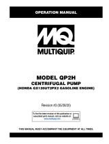
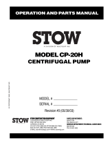
Figure 1. QP305SLT/QPT305SLT Dimensions
22.4 IN.
(57 CM.)
19.3 IN.
(49 CM.)
26.8 IN.
(68 CM.)

PAGE 10 — QP305SLT/QPT305SLT CENTRIFUGAL PUMPS • OPERATION MANUAL — REV. #5 (03/25/20)
SPECIFICATIONS (ENGINE)
Table 2. Specifications (Engines)
Engine
Model
HONDA GX340K1PKT2/
GX340U1PKT2/GX340UT2PKT2
Type
Air-cooled 4 stroke, Single
Cylinder, OHV,
Horizontal Shaft Gasoline
Engine
Bore x Stroke
3.46 in. x 2.28 in.
(88 mm x 64 mm)
Displacement 163 cc (9.9 cu-in)
Max Output 5.5 H.P./3,600 R.P.M.
Fuel Tank Capacity
Approx. 1.6 U.S. Gallons
(6.1 Liters)
Fuel Unleaded Automobile Gasoline
Lube Oil Capacity 1.16 quarts (1.1 liters)
Speed Control Method Centrifugal Fly-weight Type
Starting Method Recoil Start
Dimension
(L x W x H)
15.0 x 17.7 x 17.4 in.
(380 x 450 x 443 mm)
Dry Net Weight
69.4 lbs (31.5 Kg.)
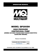
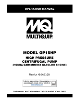
Figure 2. QP305SLT/QPT305SLT Performance Curve
US GALLONS
3.3 FT
23.3 FT
16.7 FT
10 FT

QP305SLT/QPT305SLT CENTRIFUGAL PUMPS • OPERATION MANUAL — REV. #5 (03/25/20) — PAGE 11
and leaks. A small suction leak in the hose or fittings could
prevent the pump from priming.
Elevation
Higher elevations will effect the performance of the pump.
Due to less atmospheric pressure at higher altitudes,
pumps DO NOT have the priming ability that they have at
sea level. This is due to the “thinner air” or lack of oxygen
at higher altitudes.
A general rule of thumb is that for every 1,000 feet of
elevation above sea level a pump will lose one foot of
priming ability.
For example, in Flagstaff, Arizona where the elevation is
approximately 7,000 feet, the pump would have a suction
lift of only 18 feet rather than the 25 feet at sea level.
Table 3 shows suction lift at various elevations.
Table 3. Suction Lift at Various Elevations
Altitude
Feet
(Meters)
Suction Lift in Feet (Meters)
Sea Level 10.0 (3.048) 15.0 (4.572) 20.0 (6.096) 25.0 (7.620)
2,000 (610) 8.80 (2.680) 13.2 (4.023) 17.6 (5.364) 22.0 (6.705)
4,000 (1,219) 7.80 (2.377) 11.7 (3.566) 15.6 (4.754) 19.5 (5.943)
6,000 (1,829) 6.90 (2.103) 10.4 (3.169) 13.8 (4.206) 17.3 (5.273)
8,000 (2,438) 6.20 (1.889) 9.30 (2.834) 12.4 (3.779) 15.5 (4.724)
10,000 (3,048) 5.70 (1.737) 8.60 (2.621) 11.4 (3.474) 14.3 (4.358)
Table 4 shows percentage drops in performance as
elevation increases.
Table 4. Performance Loss at Various Elevations
Altitude
Feet (Meters)
Discharge Flow Discharge Head
Sea Level 100% 100%
2,000 (610) 97% 95%
4,000 (1,219) 95% 91%
6,000 (1,829) 93% 87%
8,000 (2,438) 91% 83%
10,000 (3,048) 88% 78%
GENERAL INFORMATION
APPLICATION
The QP305SLT/QPT305SLT centrifugal pump is a high
pressure pump designed to be used for dewatering
applications. The suction port on the QP305SLT/
QPT305SLT uses a 3-inch diameter opening. There are
three discharge ports on the pump, 2 are 1-inch in diameter
and the third is 1.5-inches in diameter. This pump can
discharge water at a rate of approximately 145 gallons/
minute (gpm) or 550 liters/minute (lpm).
Centrifugal or self-priming pumps are designed to purge
air from the suction line and create a partial vacuum in the
pump body. The reduced atmospheric pressure inside the
pump allows water to flow through the suction line and into
the pump body. The centrifugal force created by the rotating
impeller pressurizes the water and expels it from the pump.
Power Plant
This centrifugal pump is powered by an 9.5 HP, air-cooled
4-stroke, single-cylinder HONDA GX340 gasoline engine
that incorporates a low “Oil Alert Feature”.
Oil Alert Feature
In the event of low oil or no oil, the HONDA GX340 engine
has a built-in oil alarm engine shutdown feature. If the oil
level is low the engine will automatically shut down.
Standard Centrifugal Pump
Standard centrifugal pumps provide an economical
choice for general purpose dewatering. These types of
pumps should only be used in clear water applications
(agricultural, industrial, residential) as they have a limited
soild handling capability of only 10% by volume.
Suction Lift
This pump is intended to be used for dewatering applications
and is capable of suction lifts up to 25 feet at sea level. For
optimal suction lift performance keep the suction hose or
line as short as possible. In general always place the pump
as close to the water as possible.
Pump Support
The pump should always be placed on solid stationary
ground in a level position.
NEVER place the pump on soft soil. The suction hose or
pipe connection should always be checked for tightness

PAGE 12 — QP305SLT/QPT305SLT CENTRIFUGAL PUMPS • OPERATION MANUAL — REV. #5 (03/25/20)
PUMP COMPONENTS
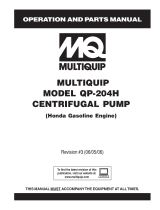
Figure 3 shows a typical application using the QP305SLT/QPT305SLT centrifugal pump. Please note that this pump is
intended for the removal of clean water.
Figure 3. QP305SLT/QPT305SLT Pump Application
1. Discharge Port 1.5-Inch — Connect a flexible rubber
hose to this 1.5-inch discharge port on the pump. Make
sure that the hose lays flat and is not kinked. Use only
recommended type discharge hose. Contact Multiquip
Parts Department for ordering information.
2. Discharge Port 1-Inch — Connect a flexible rubber
hose to these 1-inch discharge ports on the pump.
Make sure that the hose lays flat and is not kinked.
Use only recommended type discharge hose. Contact
Multiquip Parts Department for ordering information.
3. Fill Cap — Prior to operation, the pump casing should
be filled with water. Remove this cap to add water to
the pump. After the initial prime, a sufficient amount of
water will be retained in the casing so that the operator
will not need to re-prime later.
4. Worm Clamp — Used to secure the hose to the inlet
and outlet ports on the pump. Use two clamps to secure
the hose on the inlet side of the pump.
5. Discharge Hose — Connect a flexible rubber
hose to the discharge port on the pump. Make sure
that the hose lays flat and is not kinked. Use only
recommended type discharge hose. Contact Multiquip
Parts Department for ordering information.
6. Pump — The model QP305SLT/QPT305SLT is a
3-inch high pressure centrifugal pump and should
only be used in clear water applications (agricultural,
industrial, residential) as they have a limited soild
handling capability of only 10% by volume.
7. Drain Plug — Remove this plug to drain water from
the pump.
8. Suction Hose — Connect a flexible rubber hose to
the suction port on the pump. Make sure that the hose
lays flat and is not kinked. Use only recommended type
suction hose. Contact Multiquip Parts Department for
ordering information.
9. Strainer — Always attach a strainer to bottom side of
the suction hose to prevent large objects and debris
from entering the pump. Strainer should be positioned
so that it will remain completely under water. Running
the pump with the strainer above water for long periods
can damage pump.

QP305SLT/QPT305SLT CENTRIFUGAL PUMPS • OPERATION MANUAL — REV. #5 (03/25/20) — PAGE 13
6. Choke Lever — Used in the starting of a cold engine,
or in cold weather conditions. The choke enriches the
fuel mixture.
7. Air Cleaner — Prevents dirt and other debris from
entering the fuel system. Remove wing-nut on top of
air filter cannister to gain access to filter element.
8. Spark Plug — Provides spark to the ignition system.
Set spark plug gap to 0.6 - 0.7 mm (0.028 - 0.031 inch).
Clean spark plug once a week.
9. Muffler — Used to reduce noise and emissions.
10. Fuel Tank — Holds unleaded gasoline. For additional
information refer to engine owner's manual.
NOTICE
Operating the engine without an air filter, with a
damaged air filter, or a filter in need of replacement
will allow dirt to enter the engine, causing rapid engine
wear.
WARNING
Engine components can generate
extreme heat. To prevent burns,
DO NOT touch these areas while the
engine is running or immediately after
operating. NEVER operate the engine
with the muffler removed.
Figure 4. Engine Controls and Components
INITIAL SERVICING
The engine (See Figure 4) must be checked for proper
lubrication and filled with fuel prior to operation. Refer to the
manufacturers engine manual for instructions and details
of operation and servicing. The engine shown above is a
HONDA engine, operation for other types of engines may
vary somewhat.
1. Fuel Filler Cap — Remove this cap to add unleaded
gasoline to the fuel tank. Make sure cap is tightened
securely. DO NOT over fill.
2. Throttle Lever — Used to adjust engine RPM speed
(lever advanced forward SLOW, lever back toward
operator FAST).
3. Engine ON/OFF Switch — ON position permits engine
starting, OFF position stops engine operations.
4. Recoil Starter (pull rope) — Manual-starting method.
Pull the starter grip until resistance is felt, then pull
briskly and smoothly.
5. Fuel Valve Lever — OPEN to let fuel flow, CLOSE to
stop the flow of fuel.
DANGER
Adding fuel to the tank should be done
only when the engine is stopped and has
had an opportunity to cool down. In the
event of a fuel spill, DO NOT attempt to
start the engine until the fuel residue has
been completely wiped up, and the area
surrounding the engine is dry.
BASIC ENGINE

PAGE 14 — QP305SLT/QPT305SLT CENTRIFUGAL PUMPS • OPERATION MANUAL — REV. #5 (03/25/20)
INSPECTION (ENGINE)
CAUTION
DO NOT attempt to operate the pump
until the Safety Information, General
Information and Inspection sections
of this manual have been read and
thoroughly understood.
BEFORE STARTING
1. Read safety instructions at the beginning of manual.
2. Clean the pump, removing dirt and dust, particularly
the engine cooling air inlet, carburetor and air cleaner.
3. Check the air filter for dirt and dust. If air filter is dirty,
replace air filter with a new one as required.
4. Check carburetor for external dirt and dust. Clean with
dry compressed air.
5. Check fastening nuts and bolts for tightness.
Engine Oil Check
1. To check the engine oil level, place the pump on secure
level ground with the engine stopped.
2. Remove the filler dipstick from the engine oil filler hole
(See Figure 5) and wipe clean.
Figure 5. Engine Oil Dipstick (Removal
3. Insert and remove the dipstick without screwing it into
the filler neck. Check the oil level shown on the dipstick.
4. If the oil level is low (See Figure 6), fill to the edge
of the oil filler hole with the recommended oil type
(Table 5). Maximum oil capacity is 1.16 quarts
(1.1 liters).
Figure 6. Engine Oil DipStick (Oil Level
Fuel Check
1. Remove the gasoline cap located on top of fuel tank.
2. Visually inspect to see if the fuel level is low. If fuel is
low, replenish with unleaded fuel.
3. When refueling, be sure to use a strainer for filtration.
DO NOT top-off fuel. Wipe up any spilled fuel
immediately!
UPPER LIMIT
LOWER LIMIT
Table 5. Oil Type
Season Temperature Oil Type
Summer 25°C or Higher SAE 10W-30
Spring/Fall 25°C~10°C SAE 10W-30/20
Winter 0°C or Lower SAE 10W-10
DANGER
Motor fuels are highly flammable and can
be dangerous if mishandled. DO NOT
smoke while refueling. DO NOT attempt
to refuel the pump if the engine is hot!
or running.

QP305SLT/QPT305SLT CENTRIFUGAL PUMPS • OPERATION MANUAL — REV. #5 (03/25/20) — PAGE 15
7. The discharge hose is usually a collapsible
(thin-walled) hose, however if a thin-walled discharge
hose is not available, a rigid suction hose can be
substituted in its place.
8. Make sure the suction strainer (See Figure 3) is
clean and securely attached to the water end of the
suction hose. The strainer is designed to protect the
pump by preventing large objects from being pulled in
to the pump.
1. Place pump as near to water as possible, on a firm
flat, level surface.
2. To prime pump, remove fill cap (See Figure 3) and fill
pump casing with water. If the pump casing is not filled
with water before starting, it will not begin pumping.
3. Attach suction and discharge hoses to the pump. Check
that all hoses are securely attached to the pump. Make
certain suction hose (See Figure 3) does not have
any air leakage. Tighten hose clamps and couplings
as required.
4. It is recommended that 2 clamps be used when
securing the suction hose to the inlet side (suction)
of the pump.
5. Remember suction hoses must be rigid enough not to
collapse when the pump is in operation.
6. Check that the discharge hose (See Figure 3) is not
restricted. Place hose so that it lays as straight as it is
possible on the ground. Remove any twists or sharp
bends from hose which may block the flow of water.
NOTICE
Suction and discharge hoses are available from
Multiquip. Contact your nearest dealer for more
information.
CAUTION
The strainer should be positioned so it will remain
completely under water. Running the pump with the
strainer above water for long periods can damage the
pump.
SETUP

PAGE 16 — QP305SLT/QPT305SLT CENTRIFUGAL PUMPS • OPERATION MANUAL — REV. #5 (03/25/20)
OPERATION
STARTING THE ENGINE
1. Place the engine fuel valve lever (See Figure 7) to the
ON position.
Figure 7. Engine Fuel Valve Lever (ON Position)
2. Move the throttle lever (See Figure 8) away from the
slow position, about 1/3 of the way toward the fast
position.
Figure 8. Throttle Lever (1/3 Start Position
3. Place the choke lever (See Figure 9) in the CLOSED
position if starting a cold engine.
Figure 9. Engine Choke Lever (Closed)
CAUTION
DO NOT attempt to start the engine unless the pump
has previously been primed with water. Severe pump
damage will occur if pump has not been primed.
4. Place the choke lever (See Figure 10) in the OPEN
position if starting a warm engine or the temperature
is warm.
Figure 10. Engine Choke Lever (Open)
5. Place the engine ON/OFF switch (See Figure 11) in
the ON position.
Figure 11. Engine ON/OFF Switch (ON Position)
6. Grasp the starter grip (See Figure 12) and slowly pull
it out. The resistance becomes the hardest at a certain
position, corresponding to the compression point. Pull
the starter grip briskly and smoothly for starting.
Figure 12. Starter Grip
7. If the engine has started and the choke lever was
moved to the CLOSED position to start the engine,
gradually move the choke lever to the OPEN position
(Figure 13) as the engine warms up. If the engine has
not started repeat steps 1 through 6.

QP305SLT/QPT305SLT CENTRIFUGAL PUMPS • OPERATION MANUAL — REV. #5 (03/25/20) — PAGE 17
OPERATION
Figure 13. Choke Lever (Open)
8. Before the pump is placed in to operation, run the
engine for several minutes. Check for fuel leaks, and
noises that would associate with a lose component.
9. To begin pumping, place the throttle lever (See
Figure 13) in the RUN position. If water is not flowing
out of the discharge port, turn off the engine and check
for and clear any obstructions within the suction hose.
Figure 14. Throttle Lever (Run)
WARNING
Water must always be flowing through the pump casing
while the engine is running. Loss of flow may be the
result of a loss of prime, restricted water flow or a dead-
head situation. Please note that in such a condition,
water in the pump can reach temperatures of 150-200°F
in 15 to 20 minutes. This can cause serious burns if
this hot water comes into contact with unprotected skin.
Before touching or opening the fill plug or drain plug,
first turn off the engine and allow the pump casing to
cool to the touch, and then open the pump carefully.
Be cautious of any built up water pressure.
CAUTION
ALWAYS run engine at full speed while pumping.
STOPPING THE ENGINE
Normal Shutdown
1. Move the throttle lever to the IDLE position
(See Figure 14) and run the engine for three minutes
at low speed.
Figure 15. Throttle Lever (Idle)
2. After the engine cools, turn the engine ON/OFF switch
to the OFF position (See Figure 15).
Figure 16. Engine ON/OFF Switch (OFF)
3. Place the fuel shut-off lever (See Figure 16) in the
OFF position
Figure 17. Fuel Valve Lever (OFF)
Emergency Shutdown
1. Move the throttle lever quickly to the IDLE position, and
place the engine ON/OFF switch in the OFF position.

PAGE 18 — QP305SLT/QPT305SLT CENTRIFUGAL PUMPS • OPERATION MANUAL — REV. #5 (03/25/20)
PUMP VACUUM TEST
To perform the pump vacuum test do the following:
1. Remove the pump fill cap (See Figure 3), and fill the
pump with water.
2. Start the engine as outlined in the initial start-up
section, and wait for the pump to begin pumping.
3. As shown in Figure 18, place a water hose inside
the discharge opening of the pump, and turn on the
water. This flow of water into the discharge opening
will prevent the pump from running dry.
4. Place the Pump Vacuum Tester (P/N 7000030) over the
pump suction (inlet) opening (See Figure 18) with the
vacuum gauge facing upwards. It may be necessary
to apply a small amount of water around the rubber
seal of the vacuum tester to make a good suction fit.
5. Check and make sure that there are no air leaks
between the vacuum tester and the inlet port on the
pump. If air leaks are present reseat vacuum tester.
6. Run the pump for a few minutes while monitoring the
vacuum gauge. If the gauge indicates a reading
between -25 and -20 in. Hg. (inches of mercury) then
it can be assumed that the pump is working correctly.
7. If the vacuum tester gauge indicates a reading below
-20 in. Hg, it can then be assumed that the pump is
not functioning correctly, and corrective action needs
to be taken.
8. To test the flapper valve, shutdown the engine. The
vacuum tester should remain attached to the pump
suction inlet port by vacuum. This indicates the pump's
flapper valve is seating properly to hold water in the
suction hose when the engine is stopped. This prevents
backflow and allows for faster priming when the engine
is restarted.
NOTICE
25 in. Hg (inches of mercury) translates into 25 feet of
lift at sea level.
MAINTENANCE (PUMP)
CAUTION
DO NOT attempt to start the engine unless the pump
has previously been primed with water. Severe pump
damage will occur if pump has not been primed.

QP305SLT/QPT305SLT CENTRIFUGAL PUMPS • OPERATION MANUAL — REV. #5 (03/25/20) — PAGE 19
MAINTENANCE (PUMP)
Figure 18. Pump Vacuum Tester
CAUTION
DO NOT run pump without water.

PAGE 20 — QP305SLT/QPT305SLT CENTRIFUGAL PUMPS • OPERATION MANUAL — REV. #5 (03/25/20)
ENGINE MAINTENANCE
Perform engine maintenance procedures as referenced by Table 6 below:
Table 6. Engine Maintenance Schedule
Description (3) Operation Before
First
Month or
10 hrs
Every 3
Months or
25 hrs
Every 6
Months or
50 hrs
Every
Year or
100 hrs
Every 2
Years or
200 hrs
Engine Oil
CHECK X
CHANGE X
Air Cleaner
CHECK X
CHANGE X (1)
All Nuts and
Bolts
Re-tighten If
Necessary
X
Spark Plug
CHECK-CLEAN X
REPLACE X
Cooling Fins CHECK X
Spark Arrester CLEAN X
Fuel Tank CLEAN X
Fuel Filter CHECK X
Idle Speed CHECK-ADJUST X (2)
Valve Clearance CHECK-ADJUST X (2)
Fuel lines CHECK Every 2 years (replace if necessary) (2)
1. Service more frequently when used in DUSTY areas.
2. These items should be serviced by your service dealer, unless you have the proper tools and are mechanically
proficient. Refer to the HONDA shop Manual for service procedures.
3. For commercial use, log hours of operation to determine proper maintenance intervals.
NOTICE
Refer to manufacturer engine manual for specific
servicing instructions.
MAINTENANCE (ENGINE)
/