DM OUTPUTS (SLOT 2)
DigitalMedia
Switcher
2
quickstart guide
DM-TX-Series
www.crestron.com
888.273.7876 201.767.3400
©2010 Specifications subject to
change without notice.
QUICKSTART DOC. 6804C (2024043) 01.10
For details, refer to the latest revision of the DM-TX-100, DM-TX-200,
and/or DM-TX-300N series DigitalMedia
™
Transmitter Guides, Doc. 6810,
6741, or 6907, respectively.
DigitalMedia
™
Transmitters
All brand names, product names, and trademarks
are the property of their respective owners.
DM-TX-Series
3
Connecting to DigitalMedia Room Controller or DigitalMedia Switcher
Using a DigitalMedia
™
cable (DM-CBL-P or DM-CBL-NP), connect the
transmitter(s) directly to a DigitalMedia Room Controller (if required, first connect
to a DigitalMedia Repeater and then connect the output of the repeater to a room
controller), or connect the transmitter(s) to a DigitalMedia Switcher (via a
DMC-CAT/DMC-F interface card).
NOTE: DigitalMedia cable should have a minimum length of 15 feet (4.6 meters).
1. Configurations with a transmitter connected to a room controller require a
power supply, PW-2407RU, connected either to the transmitter or to the room
controller. For configurations using DM CAT cables, the power supply must be
purchased; for configurations using fiber cable, the power supply is provided.
2. Configurations with a DigitalMedia Switcher may not require an additional
power supply; the switcher typically supplies power for the transmitter. Use the
Crestron Power Calculator to verify that there is enough DMNet power on the
switcher.
3. For detailed instructions on the DigitalMedia Room Controller (DM-RMC-100
and DM-RMC-100-F) or the DigitalMedia Switcher, refer to the latest version
of their respective guides (Doc. 6743, 6744, and 6755) which can be obtained
from the Crestron website (www.crestron.com/manuals).
4
100-250V~7.0A
50/60 Hz
G
CRESTRON
ELECTRONICS INC, ROCKLEIGH, NJ 07647 USA
RISK OF ELECTRIC SHOCK
DO NOT OPEN
AVIS: RISQUE DE CHOC ELECTRIQUE NE PAS OUVRIR
HDMI OUT
DVI-I IN
AUDIO IN
L R
+ - G + -
AUDIO IN
VIDEO IN
SPDIF L
R Y
Pb/Y
Pr/C/COMP
HDMI IN
DM OUT
D M
24 A B G
IR
S G USB HID
COM LAN
GND
TX
RX
RTS
CTS
SETUP
G
ELECTRONICS INC., ROCKLEIGH, NJ 07647 USA
CRESTRON
Setting Up Ethernet
1. Transmitters connected to a room controller use their own configu-
ration settings. The units ship in DHCP mode, but the following
static addresses can be set on the units by holding the SETUP
button depressed while the unit boots up:
• The DM-TX-100, 200, and 300 series units default to
192.168.1.231/232/233.
• The DM-RMC-100/100-F defaults to 192.168.1.241/242.
NOTE: This process overwrites any current settings. Also, for the
DM-TX-100/100-F, the USB console is enabled and HID functionality
is blocked until reboot.
Connecting AV Sources, Outputs, and Verifying Signals
Check that the DM input of the room controller or DigitalMedia Switcher are
connected to the transmitters, and connect/turn on power. Check the transmitter
LEDs, the output display, and verify the signal settings.
• Check the room controller PWR LED ( on/green).
• Check the DM LINK LED ( on/green).
• Check that the VIDEO LED is on/green when a video signal is detected.
The DM-TX-100/100-F does not have video switching because there is only one
AV input.
The DM-TX-200 has auto routing functionality by default:
• If no signal is present on HDMI IN, RGB IN and AUDIO IN will be
routed.
• If a signal is present on HDMI IN and no audio is embedded in the
video, (i.e., a DVI signal) HDMI IN video and AUDIO IN audio will be
routed.
• If a signal is present on HDMI IN with audio embedded in the signal,
HDMI IN audio and video will be routed.
The 300N/300N-F have front panel controls for making selections.
Setup of the IP address for the DigitalMedia transmitters depends on
the way the transmitters are configured within the DigitalMedia system.
DigitalMedia
Transmitter
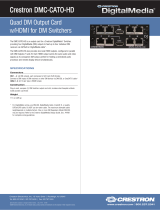
Connect the cable from the
PW-2407 power supply to
either end of the DigitalMedia
“DMNet” Cable, as shown in
the diagram to the right.
Connection to Room Controller (DM CAT)
Connection to DigitalMedia Switcher
DigitalMedia
Transmitter
Room Controller or
DigitalMedia Switcher
DigitalMedia
OR
PC/Laptop
OR
2. Transmitters connected to a DigitalMedia Switcher are
configured automatically by the switcher.
3. With a PC connected as shown in the diagram below,
use Crestron Toolbox
™
to set the IP addresses of the
transmitter and room controller or DigitalMedia Switcher.
DigitalMedia
Power Supply
PW-2407RU
(Not Supplied)
OR
Red
Orange
Gray
Black
24 A B G
Gnd
“DMNet”
Control & Power
From
PW-2407RU
HDMI
RGB
USB HID AUDIO
IN
PWR
DM
LINK
HDMI
IN
RGB IN
SETUP
RESET
DM OUT
D M
G B A 24
DigitalMedia
Transmitter
DM-RMC-100-F
Connection to Room Controller (Fiber)
HDMI OUT
DVI-I IN
AUDIO IN
L R
+ - G + -
AUDIO IN
VIDEO IN
SPDIF L
R Y
Pb/Y
Pr/C/COMP
HDMI IN
DM OUT
D M
24 A B G
IR
S G USB HID
COM LAN
GND
TX
RX
RTS
CTS
SETUP
G
ELECTRONICS INC., ROCKLEIGH, NJ 07647 USA
CRESTRON
DigitalMedia
Transmitter
DigitalMedia
Transmitter
Power
Supply
(Supplied)
Power
Supply
(Supplied)
Fiber configurations
require local power
supplies (supplied).
Power supply
(supplied) required
for fiber configurations.
Fiber
Cable
DigitalMediaOR
Fiber Cable
5
HDMI
COM
GND
TX
RX
RTS
CTS
SENS
S G
IR
1 2
S G S G
USB
RELAY
1 2
PWR
DM
LINK
VIDEO
CNTRL
SETUP
CRESTRON
DM-RMC-100-F
DM ROOM CONTROLLER
G 24
PWR
DM INPUT
D
M
LAN
Fiber Cable
DM-RMC-100
HDMI
COM
GND
TX
RX
RTS
CTS
SENS
S G
IR
1 2
S G S G
USB
RELAY
1 2
CRESTRON
DM-RMC-100
DM ROOM CONTROLLER
PWR
DM
LINK
VIDEO
CNTRL
SETUP
24 A B G
DM IN
D
M
LAN
RESET
USB
Cable
USB
Cable