Page is loading ...

SINGLE ZONE HIGH EFFICIENCY STANDARD
WALL MOUNTED INSTALLATION MANUAL
Single Zone High Efciency:
LS090HSV4, LS120HSV4, LS180HSV4

The instructions included in this manual must be followed to prevent product malfunction, property damage, injury, or death to the user or
other people. Incorrect operation due to ignoring any instructions will cause harm or damage. The level of seriousness is classified by the
symbols described below.
Do not throw away, destroy, or lose this manual.
Please read carefully and store in a safe place for future reference.
Content familiarity required for proper installation.
A summary list of safety precautions begins on page 3.
For more technical materials such as submittals, engineering
databooks, and catalogs, visit www.lghvac.com.
For continual product development, LG Electronics U.S.A., Inc., reserves the right to change specifications without notice.
©LG Electronics U.S.A., Inc.
This document, as well as all reports, illustrations, data, information, and other materials are the property of LG Electronics U.S.A., Inc.
PROPRIETARY DATA NOTICE
This document, as well as all reports, illustrations, data, information, and
other materials are the property of LG Electronics U.S.A., Inc., and are
disclosed by LG Electronics U.S.A., Inc., only in confidence.
This document is for design purposes only.
IM-SZ-HighEfficiencyInverter_HSV4-01-15

3
Safety Instructions
Due to our policy of continuous product innovation, some specifications may change without notification.
©LG Electronics U.S.A., Inc., Englewood Cliffs, NJ. All rights reserved. “LG” is a registered trademark of LG Corp.
SAFETY INSTRUCTIONS
The instructions below must be followed to prevent product malfunction, property damage, injury or death to the user or other people. Incor-
rect operation due to ignoring any instructions will cause harm or damage. The level of seriousness is classified by the symbols described
below.
INSTALLATION
TABLE OF SYMBOLS
This symbol indicates an imminently hazardous situation which, if not avoided, will result in death or serious
injury.
This symbol indicates a potentially hazardous situation which, if not avoided, could result in death or serious
injury.
This symbol indicates a potentially hazardous situation which, if not avoided, may result in minor or
moderate injury.
This symbol Indicates situations that may result in equipment or property damage accidents only.
This symbol indicates an action should not be completed.
Do not install, remove, or re-install the unit by yourself
(customer). Ask the dealer or an authorized technician to
install the unit.
Improper installation by the user may result in water leakage, re,
explosion, electric shock, physical injury or death.
For replacement of an installed unit, always contact an
authorized LG service provider.
There is risk of re, electric shock, explosion, and physical injury or death.
The unit is shipped with refrigerant and the service valves
closed. Do not open service valves on the unit until all
non-condensibles have been removed from the piping sys-
tem and authorization to do so has been obtained from the
commissioning agent.
There is a risk of physical injury or death.
Do not run the compressor with the service valves closed.
There is a risk of equipment damage, explosion, physical injury, or death.
Periodically check that the outdoor frame is not damaged.
There is a risk of explosion, physical injury, or death.
Replace all control box and panel covers.
If cover panels are not installed securely, dust, water and animals may
enter the unit, causing re, electric shock, and physical injury or death.
Always check for system refrigerant leaks after the unit has
been installed or serviced.
Exposure to high concentration levels of refrigerant gas may lead to ill-
ness or death.
Wear protective gloves when handling equipment. Sharp
edges may cause personal injury.
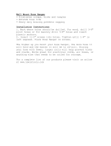
Dispose the packing materials safely.
• Packing materials, such as nails and other metal or wooden parts,
may cause puncture wounds or other injuries.
• Tear apart and throw away plastic packaging bags so that children
may not play with them and risk suffocation and death.
Install the unit considering the potential for strong winds or
earthquakes.
Improper installation may cause the unit to fall over, resulting in physical
injury or death.
Do not change the settings of the protection devices.
If the pressure switch, thermal switch, or other protection device is
shorted and forced to operate improperly, or parts other than those
specied by LG are used, there is risk of re, electric shock, explosion,
and physical injury or death.
Do not install the unit on a defective stand.
There is a risk of physical injury.
Don’t store or use ammable gas / combustibles near the unit.
There is risk of re, explosion, and physical injury or death.

4
Single Zone High Efciency Wall Mounted Installation Manual
Due to our policy of continuous product innovation, some specifications may change without notification.
©LG Electronics U.S.A., Inc., Englewood Cliffs, NJ. All rights reserved. “LG” is a registered trademark of LG Corp.
SAFETY INSTRUCTIONS
INSTALLATION - CONTINUED
Don’t install the unit where it’s directly exposed to ocean winds.
Ocean winds may cause corrosion, particularly on the condenser and
evaporator ns, which, in turn could cause product malfunction or inef-
cient performance.
When installing the unit in a low-lying area, or a location that
is not level, use a raised concrete pad or concrete blocks to
provide a solid, level foundation.
This may prevent water damage and reduce abnormal vibration.
Properly insulate all cold surfaces to prevent “sweating.”
Cold surfaces such as uninsulated piping can generate condensate that
may drip and cause a slippery oor condition and/or water damage to walls.
When installing the unit in a hospital, mechanical room, or
similar electromagnetic eld (EMF) sensitive environment,
provide sufcient protection against electrical noise.
Inverter equipment, power generators, high-frequency medical equip-
ment, or radio communication equipment may cause the air conditioner to
operate improperly. The unit may also affect such equipment by creating
electrical noise that disturbs medical treatment or image broadcasting.
Do not use the product for special purposes such as
preserving foods, works of art, wine coolers, or other
precision air conditioning applications. The equipment is
designed to provide comfort cooling and heating.
There is risk of property damage.
Do not make refrigerant substitutions. Use R410A only.
If a different refrigerant is used, or air mixes with original refrigerant, the
unit will malfunction and be damaged.
Keep the unit upright during installation to avoid vibration or
water leakage.
Do not install the unit in a noise sensitive area.
When connecting refrigerant tubing, remember to allow for
pipe expansion.
Improper piping may cause refrigerant leaks and system malfunction.
Take appropriate actions at the end of HVAC equipment life
to recover, recycle, reclaim or destroy R410A refrigerant
according to applicable U.S. Environmental Protection
Agency (EPA) rules.
Periodically check that the outdoor frame is not damaged.
There is a risk of equipment damage.
Install the unit in a safe location where nobody can step on
or fall onto it. Do not install the unit on a defective stand.
There is risk of unit and property damage.
Install the drain hose to ensure adequate drainage.
There is a risk of water leakage and property damage.
Don’t store or use ammable gas / combustibles near the unit.
There is risk of product failure.
Always check for system refrigerant leaks after the unit has
been installed or serviced.
Low refrigerant levels may cause product failure
The unit is shipped with refrigerant and the service valves
closed. Do not open service valves on the unit until all
non-condensibles have been removed from the piping system
and authorization to do so has been obtained from the com-
missioning agent.
There is a risk of refrigerant contamination, refrigerant loss and equip-
ment damage.
Do not run the compressor with the service valves closed.
There is a risk of equipment damage.
Be very careful when transporting the product.
• Do not attempt to carry the product without assistance.
• Some products use polypropylene bands for packaging. Do not use
polypropylene bands to lift the unit.
• Suspend the unit from the base at specified positions.
• Support the unit a minimum of four points to avoid slippage from
rigging apparatus.
If the air conditioner is installed in a small space, take
measures to prevent the refrigerant concentration from
exceeding safety limits in the event of a refrigerant leak.
Consult the latest edition of ASHRAE (American Society of Heating,
Refrigerating, and Air Conditioning Engineers) Standard 15. If the
refrigerant leaks and safety limits are exceeded, it could result in personal
injuries or death from oxygen depletion.
Install the unit in a safe location where nobody can step on or
fall onto it.
There is risk of physical injury or death.

5
Safety Instructions
Due to our policy of continuous product innovation, some specifications may change without notification.
©LG Electronics U.S.A., Inc., Englewood Cliffs, NJ. All rights reserved. “LG” is a registered trademark of LG Corp.
SAFETY INSTRUCTIONS
High voltage electricity is required to operate this system.
Adhere to the National Electrical Codes and these
instructions when wiring.
Improper connections and inadequate grounding can cause accidental
injury or death.
Always ground the unit following local, state, and National
Electrical Codes.
Turn the power off at the nearest disconnect before servicing
the equipment.
Electrical shock can cause physical injury or death.
Properly size all circuit breakers or fuses.
There is risk of re, electric shock, explosion, physical injury or death.
WIRING
The information contained in this manual is intended for use
by an industry-qualied, experienced, certied electrician
familiar with the U.S. National Electric Code (NEC) who is
equipped with the proper tools and test instruments.
Failure to carefully read and follow all instructions in this manual can
result in equipment malfunction, property damage, personal injury or death.
All electric work must be performed by a licensed electrician
and conform to local building codes or, in the absence of
local codes, with the National Electrical Code, and the
instructions given in this manual.
If the power source capacity is inadequate or the electric work is not per-
formed properly, it may result in re, electric shock, physical injury or death.
Refer to local, state, and federal codes, and use power wires
of sufcient current capacity and rating.
Wires that are too small may generate heat and cause a re.
Secure all eld wiring connections with appropriate wire
strain relief.
Improperly securing wires will create undue stress on equipment power
lugs. Inadequate connections may generate heat, cause a re and phys-
ical injury or death.

6
Single Zone High Efciency Wall Mounted Installation Manual
Due to our policy of continuous product innovation, some specifications may change without notification.
©LG Electronics U.S.A., Inc., Englewood Cliffs, NJ. All rights reserved. “LG” is a registered trademark of LG Corp.
SAFETY INSTRUCTIONS
Clean up the site after installation is nished, and check
that no metal scraps, screws, or bits of wiring have been left
inside or surrounding the unit.
Do not use this equipment in mission critical or special-
purpose applications such as preserving foods, works of art,
wine coolers or refrigeration. The equipment is designed to
provide comfort cooling and heating.
Oil, steam, sulfuric smoke, etc., can signicantly reduce the performance
of the unit, or damage its parts.
Provide power to the compressor crankcase heaters at least
six (6) hours before operation begins.
Starting operation with a cold compressor sump(s) may result in severe
bearing damage to the compressor(s). Keep the power switch on during
the operational season.
Do not block the inlet or outlet.
Unit may malfunction.
Securely attach the electrical part cover to the indoor unit
and the service panel to the outdoor unit.
Non-secured covers can result in re due to dust or water in the service
panel.
Periodically verify the equipment mounts have not
deteriorated.
If the base collapses, the unit could fall and cause property damage
or product failure.
Do not allow water, dirt, or animals to enter the unit.
There is risk of unit failure.
OPERATION
Do not provide power to or operate the unit if it is ooded or
submerged.
There is risk of re, electric shock, physical injury or death.
Use a dedicated power source for this product.
There is risk of re, electric shock, physical injury or death.
Do not operate the disconnect switch with wet hands.
There is risk of re, electric shock, physical injury or death.
Periodically verify the equipment mounts have not
deteriorated.
If the base collapses, the unit could fall and cause physical injury or death.
If gas leaks out, ventilate the area before operating the unit.
If the unit is mounted in an enclosed, low-lying, or poorly ventilated area,
and the system develops a refrigerant leak, it may cause re electric
shock, explosion, physical injury or death.
To avoid physical injury, use caution when cleaning or
servicing the air conditioner.
Do not allow water, dirt, or animals to enter the unit.
There is risk of re, electric shock, physical injury or death.
Avoid excessive cooling and periodically perform ventilation
to the unit.
Inadequate ventilation is a health hazard.
Do not touch the refrigerant piping during or after operation.
It can cause burns or frostbite.
Do not operate the unit with the panel(s) or protective
cover(s) removed; keep ngers and clothing away from
moving parts.
The rotating, hot, cold, and high-voltage parts of the unit can cause
physical injury or death.
Periodically, check power cord and plug for damage.
Cord must be replaced by the manufacturer, its service agent, or similar
qualied persons in order to avoid physical injury and/or electric shock.
Do not open the inlet grille of the unit during operation. Do
not operate the unit with the panels or guards removed. Do
not insert hands or other objects through the inlet or outlet
when the unit is plugged in. Do not touch the electrostatic
lter, if the unit includes one.
The unit contains sharp, rotating, hot, and high voltage parts that can
cause personal injury and/or electric shock.
Securely attach the electrical part cover to the indoor unit
and the service panel to the outdoor unit.
Non-secured covers can result in burns or electric shock due to dust or
water in the service panel.

7
Due to our policy of continuous product innovation, some specifications may change without notification.
©LG Electronics U.S.A., Inc., Englewood Cliffs, NJ. All rights reserved. “LG” is a registered trademark of LG Corp.
TABLE OF CONTENTS
Safety Instructions ................................................................................ 3
General Data .......................................................................................... 8
Unit Nomenclature ............................................................................... 8
Single Zone High Efciency Unit Specications .................................. 9
Electrical ............................................................................................ 10
R410A Refrigerant ............................................................................. 10
General Installation Guidelines ...........................................................11
Location Selection ..............................................................................11
Oceanside Applications ..................................................................... 12
Mounting Bolt Location ...................................................................... 13
Required Clearances ......................................................................... 14
Mounting of Indoor Unit Installation Plate .......................................... 15
Mounting of Indoor Unit ..................................................................... 16
Piping Preparation ............................................................................. 17
Piping Materials and Handling ........................................................... 18
Piping Support ................................................................................... 23
Underground Piping ........................................................................... 24
Refrigerant Piping Connections ......................................................... 26
Refrigerant Piping System Limitations ............................................... 26
Installation Overview ......................................................................... 26
Directional Pipe Formation ................................................................ 27
Drain Hose ......................................................................................... 28
Outdoor Unit Connections ................................................................. 29
Indoor Unit Connections .................................................................... 30
Bundling and Cutting Line ................................................................. 31
Refrigerant Piping Insulation ........................................................ 32-34
Air Purging ......................................................................................... 35
Leak Test/Soap Method Check .......................................................... 36
Evacuation of Lines ........................................................................... 37
Finishing Up ....................................................................................... 37
Remote Controller ............................................................................. 37
Pump Down, Cooling Only Mode ...................................................... 38
Electrical Wiring .................................................................................. 39
General Information and Safety Guidelines ....................................... 39
Power Wiring Specications and Best Practices ............................... 40
Controllers ......................................................................................... 41
Indoor Unit Electrical Connections ............................................... 42-43
Outdoor Unit Electrical Connections ............................................. 44-45
Self Diagnosis Functions ............................................................. 46-47
LG SIMS - Self Diagnosis Functions ........................................... 48-49
Troubleshooting .................................................................................. 50
Error Codes ................................................................................. 50-52
Refrigerant Leaks .............................................................................. 53
Installation Checklist ...................................................................... 54-55

8
Single Zone High Efciency Wall Mounted Installation Manual
Due to our policy of continuous product innovation, some specifications may change without notification.
©LG Electronics U.S.A., Inc., Englewood Cliffs, NJ. All rights reserved. “LG” is a registered trademark of LG Corp.
GENERAL DATA
Single Zone Wall Mount Indoor and Outdoor Units
LS
N 090 HSV 4
Generation
3 = Third
4 = Fourth
Indoor/Outdoor Product
HSV = High Efficiency
HV = Standard
HLV = Extended Pipe
HEV = Mega
HXV = Mega 115V
Nominal Capacity
(Nominal cooling capacity in Btu/h)
090/091 = 9,000
120/121 = 12,000
180/181 = 18,000
240 = 24,000
300/307 = 30,000
360 = 36,000
Type
N = Indoor Wall Mount Unit
U = Outdoor Heat Pump Unit
Family
LS= High Efficiency Wall Mount / Standard / Extended Pipe / Mega
Unit Nomenclature

9
Product Data
Due to our policy of continuous product innovation, some specifications may change without notification.
©LG Electronics U.S.A., Inc., Englewood Cliffs, NJ. All rights reserved. “LG” is a registered trademark of LG Corp.
GENERAL DATA
Single Zone High Efciency Unit Specications
Type Single Zone High Efciency Units
System Model Number (IDU/ODU)
LS090HSV4
(LSN090HSV4/LSU090HSV4)
LS120HSV4
(LSN120HSV4/LSU120HSV4)
LS180HSV4
(LSN180HSV4/LSU180HSV4)
Nominal Cooling Capacity (Btu/h) 9,000 11,200 18,200
Cooling Power Input
1
(kW) 0.68 0.90 1.45
Nominal Heating Capacity (Btu/h)
1
10,800 13,300 22,000
Heating Power Input
1
(kW) 0.70 1.0 1.76
COP 4.51 3.90 3.66
EER 13.3 12.5 12.6
SEER 21.5 21.5 20.5
HSPF 10.8 11.0 9.7
Power Supply (V/Hz/Ø) 208-230/60/1
Outdoor Unit Operating Range
2
Cooling (°F DB) 14 to 118
Heating (°F WB) -4 to +65
Indoor Unit Operating Range
2
Cooling (°F WB) 53 to 75
Heating (°F DB) 60 to 86
Unit Data
Refrigerant Type
3
R410A
Refrigerant Control EEV
IDU Sound Pressure
4
dB(A) (H/M/L/Sleep) 38/33/23/19 39/33/23/19 45/40/35/29
ODU Sound Pressure
4
dB(A) 45 45 53
Power/Communication Cable
5
(No. x AWG) 4 x 18
IDU Net/Shipping Weight (lbs) 20/26 20/26 31/36
ODU Net/Shipping Weight (lbs) 75/79 75/79 121/131
Compressor
Compressor Type (Qty) Single Rotary (1) Single Rotary (1) Twin Rotary (1)
Fan
IDU Type (Qty) Cross Flow (1)
ODU Type (Qty) Propeller (1)
Motor/Drive Brushless Digitally Controlled/Direct
Airflow Rate
IDU Max/H/M/L (CFM) 423/353/272/191 423/353/272/191 735/622/509/399
ODU Max (CFM) 1,165 1,165 2,119
Piping
Liquid Line (in, OD) 1/4 1/4 3/8
Vapor Line (in, OD) 3/8 3/8 5/8
Condensation Line (OD, ID) 27/32, 5/8 27/32, 5/8 27/32, 5/8
Additional Refrigerant Charge (oz/ft) 0.22 0.22 0.38
Pipe Length
6
(ft) (Min./Max.) 6.6/65.6 6.6/65.6 9.8/98.4
Piping Length
6
(no add’l refrigerant, ft) 41.0 41.0 24.6
Max Elevation Difference (ft) 32.8 32.8 49.2
Table 1: Single Zone High Efciency Unit Specications
EEV: Electronic Expansion Valve IDU: Indoor Unit ODU: Outdoor Unit
1
Power Input is rated at high speed.
2
Optional Low Ambient Wind Baffle Kit allows operation down to 0°F in cooling mode.
3
Take appropriate actions at the end of HVAC equipment life to recover, recycle, reclaim or destroy
R410A refrigerant according to applicable regulations (40 CFR Part 82, Subpart F) under section 608 of
CAA.
4
Sound Pressure levels are tested in an anechoic chamber under ISO Standard 1996.
5
All power/communication cables to be minimum 18 AWG, 4-conductor, stranded, shielded and must
comply with applicable and national code.
6
Piping lengths are equivalent.
Power wiring is field supplied and must comply with the applicable local and national codes.
This unit comes with a dry helium charge.
This data is rated 0 ft above sea level with 24.6 of refrigerant line per indoor unit and a 0 ft level
difference outdoor and indoor units.
Cooling capacity rating obtained with air entering the indoor unit at 80ºF dry bulb (DB) and 67ºF wet bulb
(WB) and outdoor ambient conditions of 95ºF dry bulb (DB) and 75ºF wet bulb (WB).
Heating capacity rating obtained with air entering the indoor unit at 70ºF dry bulb (DB) and 59ºF wet bulb
(WB) and outdoor ambient conditions of 47ºF dry bulb (DB) and 43ºF wet bulb (WB).

10
Single Zone High Efciency Wall Mounted Installation Manual
Due to our policy of continuous product innovation, some specifications may change without notification.
©LG Electronics U.S.A., Inc., Englewood Cliffs, NJ. All rights reserved. “LG” is a registered trademark of LG Corp.
GENERAL DATA
Model Number Nom. Tons
Compressor
Qty
Compressor
(A) Cool/Heat
Fan Qty ODU Fan (A) IDU Fan (A) MCA (A) MOP (A)
LS090HSV4 3/4 1 8.3/8.3 1 0.40 0.40 10 15
LS120HSV4 1 1 8.3/8.3 1 0.40 0.40 10 15
LS180HSV4 1-1/2 1 14.6/14.6 1 0.25 0.40 19 25
Table 2: Single Zone High Efciency Indoor Unit Electrical Data
Electrical/R410A Refrigerant
R410A Refrigerant
R410A refrigerant has a higher operating pressure in comparison to R22 refrigerant and, therefore, all piping system materials installed must
have a higher resisting pressure than the materials traditionally used in R22 systems.
R410A refrigerant is an azeotrope of R32 and R125, mixed at 50:50, so the ozone depletion potential (ODP) is 0. Many countries have
approved of and encouraged R410A for use as an alternate refrigerant.
Electrical
• Do not use any piping that has not been approved for use in high-pressure refrigerant systems. Improper piping may cause refrigerant
leaks and system malfunction.
• Piping wall thickness must comply with the applicable local, state, and federal codes for the 551 psi design pressure of R410A.
• Because R410A is a combination of R32 and R125, the required additional refrigerant must be charged in its liquid state. If the refrig-
erant is charged in its gaseous state, its composition changes and the system will not work properly.
Do not place the refrigerant cylinder in direct sunlight. There is risk of re, explosion, and physical injury or death.
Do not use any piping that has not been approved for use in high-pressure refrigerant systems. There is risk of re, explosion and
physical injury or death. Improper piping may also cause refrigerant leaks. If the refrigerant leaks and safety limits are exceeded, it could
result in personal injuries or death from oxygen depletion.

11
General Installation Guidelines
Due to our policy of continuous product innovation, some specifications may change without notification.
©LG Electronics U.S.A., Inc., Englewood Cliffs, NJ. All rights reserved. “LG” is a registered trademark of LG Corp.
GENERAL INSTALLATION GUIDELINES
Location Selection
Selecting the Best Location
DANGER
• To avoid the possibility of fire, do not install the unit in an area where combustible gas may generate, flow, stagnate, or leak.
• Do not install the unit in a location where acidic solution and spray (sulfur) are often used as it can cause bodily injury or death.
• Do not use the unit in environments where oil, steam, or sulfuric gas are present as it can cause bodily injury or death.
Install a fence to prevent vermin from crawling into the unit or unauthorized individuals from accessing it.
Select a location for installing the outdoor unit that will meet the following conditions:
• Where the unit will not be subjected to direct thermal radiation from other heat sources.
• Where operating sound from the unit will not disturb inhabitants of surrounding buildings.
• Where the unit will not be exposed to direct, strong winds.
• Where there is enough strength to bear the weight of the unit.
• Include space for drainage to ensure condensate flows properly out of the unit when it is in heating mode.
• Include enough space for air flow and for service access.
To ensure the outdoor unit operates properly, certain measures are required in locations where there is a possibility of heavy snowfall or severe wind-
chill or cold:
1. Prepare for severe winter wind chills and heavy snowfall, even in areas of the country where these are unusual phenomena.
2. Position the outdoor unit so that its airflow fans are not buried by direct, heavy snowfall. If snow piles up and blocks the airflow, the
system may malfunction.
3. Remove any snow that has accumulated 3-15/16 inches or more on the top of the outdoor unit.
4. Place the outdoor unit on a raised platform at least 19-11/16 inches higher than the average annual snowfall for the area. In environments
where there is a possibility of heavy snow, the frame height must be more than two (2) times the amount of average annual snowfall, and
should not exceed the width of the outdoor unit. If the frame width is wider than the outdoor unit, snow may accumulate.
5. Install a snow protection hood.
6. To prevent snow and heavy rain from entering the outdoor unit, install the suction and discharge ducts facing away from direct winds.
7. Additionally, the following conditions should be taken into consideration when the unit operates in defrost mode:
• If the outdoor unit is installed in a highly humid environment (near an ocean, lake, etc.), ensure that the site is well-ventilated and has a lot of
natural light. (Example: Install on a rooftop.)
• Sidewalks or parking lots near the outdoor unit may accumulate moisture after unit operates in defrost mode that can turn to ice.
Ambient Air Conditions
• Avoid exposing the outdoor unit to steam, combustible gases, or other corrosive elements.
• Avoid exposing the unit to discharge from boiler stacks, chimneys, steam relief ports, other air conditioning units, kitchen vents, plumbing
vents, or substances that may degrade performance or cause damage to the unit.
• When installing multiple outdoor units, avoid placing the units where discharge of one outdoor unit will blow into the inlet side of an adjacent unit.
Avoid exposing the unit to sources of extreme temperature or gases to prevent serious bodily injury.
The indoor unit may take longer to provide heat, or heating performance will be reduced in winter if the unit is installed:
1. In a narrow, shady location.
2. Near a location that has a lot of ground moisture.
3. In a highly humid environment.
4. In an area in which condensate does not drain properly.

12
Single Zone High Efciency Wall Mounted Installation Manual
Due to our policy of continuous product innovation, some specifications may change without notification.
©LG Electronics U.S.A., Inc., Englewood Cliffs, NJ. All rights reserved. “LG” is a registered trademark of LG Corp.
GENERAL INSTALLATION GUIDELINES
• Avoid installing the outdoor unit where it would be directly exposed
to ocean winds.
• Install the outdoor unit on the side of the building opposite from
direct ocean winds.
• Select a location with good drainage.
• Periodically clean dust or salt particles off of the heat exchanger
with water.
• If the outdoor unit must be placed in a location where it would
be subjected to direct ocean winds, install a concrete windbreak
strong enough to block any winds.
• Windbreak should be more than 150% of the outdoor unit’s height.
There must be 2 to 3-1/2 inches of clearance between the outdoor
unit and the windbreaker for purposes of air flow.
Additional anti-corrosion treatment may need to be applied to the
outdoor unit at oceanside locations.
Ocean winds may cause corrosion, particularly on the condenser and
evaporator ns, which, in turn could cause product malfunction or
inefcient performance.
Oceanside Applications
Figure 1: Oceanside Placement Using Windbreak
Figure 2: Placement Using Building as Shield
Oceanside Applications
Use of a Windbreak to Shield from Sea Wind
Sea wind
Windbreak
Oceanside Applications
Use of a Building to Shield from Sea Wind
Sea wind
Sea wind
Building
Building
If a windbreak is not possible, a building or larger structure must
be used to shield the outdoor unit from direct exposure to the sea
wind. The unit should be placed on the side of the building directly
opposite to the direction of the wind as shown in Figure 2.

13
General Installation Guidelines
Due to our policy of continuous product innovation, some specifications may change without notification.
©LG Electronics U.S.A., Inc., Englewood Cliffs, NJ. All rights reserved. “LG” is a registered trademark of LG Corp.
GENERAL INSTALLATION GUIDELINES
Mounting Bolt Location
General Mounting
Securely attach the outdoor unit to a condenser pad, base rails, or
another mounting platform that is securely anchored to the ground or
building structure. Attach the outdoor unit with a bolt and nut on a con-
crete or rigid mount. See Figure 3. Follow applicable local codes for
clearance, mounting, anchor and vibration attenuation requirements.
All referenced materials are to be eld-supplied. Images are not to scale.
Figure 3: Outdoor Unit Mounting Methods
Bolt
Placement
& Anti-Vibration
Pad
Piping Connection
Top of Unit
Foundation
Mounting Platform
The underlying structure or foundation must be designed to support
the weight of the unit. Avoid placing the unit in a low lying area
where water may accumulate. When installing the outdoor unit on
the wall, or roof top, anchor the mounting base securely to account
for wind, earthquake or vibration.
Tie-Downs and Wind Restraints
The strength of the Duct-free Split Single Zone Inverter system
frame is adequate to be used with field-provided wind restraint tie-
downs. The overall tie-down configuration must be approved by a
local professional engineer.
Always refer to local code when designing a wind restraint system.
Snow and Ice Conditions
In climates that experience snow build-up, place the unit on a raised platform to ensure condenser airflow. The raised support platform must
be high enough to allow the unit to remain above possible snow drifts. Mount the unit on a field-provided snow stand at a minimum height
that is equal to the average annual snowfall plus 20 inches. Design the mounting base to prevent snow accumulation on the platform in front
or back of the unit case. If necessary, provide a field fabricated hood to keep snow and ice and/or drifting snow from accumulating on the coil
surfaces. Use inlet and discharge duct or hoods to prevent snow or rain from accumulating on the fan inlet and outlet guards. Best practice
prevents snow from accumulating on top of the unit. Consider tie-down requirements in case of high winds or where required by local codes.
When deciding on a location to place the outdoor unit, be sure to choose an area where run-off from defrost will not accumulate and freeze on
sidewalks or driveways.
Proper airflow through the Single Zone outdoor unit coil is critical for correct unit operation. When installing, consider service, inlet and outlet,
and minimum allowable space requirements as illustrated in the diagrams below.
Minimum Clearance Requirements for Single Zone
Specific clearance requirements in the diagrams on the next page are for the single zone wall mount systems. Figure 4 shows the overall
minimum clearances that must be observed for safe operation and adequate airflow around the outdoor unit.
When placing the outdoor unit under an overhang, awning, sunroof or other “roof-like structure, observe the clearance requirements (as shown
in Figure 5) for height in relation to the unit. This clearance ensures that heat radiation from the condenser is not restricted around the unit. See
Figures 6 and 7 for recommendations when other obstacles are present.
Adhere to all clearance requirements if installing the unit on a roof. Be sure to level the unit and ensure that the unit is adequately anchored.
Consult local codes for rooftop mounting requirements.
Outdoor Unit Clearance

14
Single Zone High Efciency Wall Mounted Installation Manual
Due to our policy of continuous product innovation, some specifications may change without notification.
©LG Electronics U.S.A., Inc., Englewood Cliffs, NJ. All rights reserved. “LG” is a registered trademark of LG Corp.
GENERAL INSTALLATION GUIDELINES
Required Clearances
Figure 4: Outdoor Unit Clearances
Outdoor Unit Clearance
12
28
24
12
24
Unit : inch
Do not place the unit where animals and/or plants will be in the path of the warm air, or where the warm air and/or noise will disturb neighbors.
Figure 5: Outdoor Unit Sunroof/Awning Clearances
More than
12
More than
12
Sunroof
Fence or
obstacles
More than
28
Unit : inch
More than
24
9/12k Indoor Units: ≥5
18k Indoor Units: ≥8
More than 4
More than 4
At least 6.5 from the floor
Unit: Inch
Indoor Unit Clearance
Follow recommended best practices when choosing an indoor loca-
tion for the Single Zone indoor unit.
• Keep unit away from any indoor steam or excessive heat.
• No obstacles should be placed around unit.
• Condensation drain (Leakage piping) should be routed away from
the unit.
• Do not install near doorway.
• Clearance gap between any wall or enclosure and the left or right
side of the unit must be greater than 4 inches.
• From the top of the unit to the ceiling there must be greater than 5
or 8 inches of clearance (depending on indoor unit model).
• Unit should be at least 6.5 feet from the oor for adequate clearance.
Figure 6: Clearances Where There Are Obstacles on Both Air
Inlet and Outlet Sides (Obstacle on the Outlet Side is Lower
Than the Outdoor Unit)
Figure 7: Clearances Where There are Obstacles Above and on Both Air Inlet
and Outlet Sides (Obstacle on the Outlet Side is Lower Than the Outdoor Unit)
Figure 8: Indoor Unit Clearance Recommendations
Minimum
28
Minimum
12
Unit: Inch
Minimum
12
79
24
Minimum 28
Unit: Inch

15
General Installation Guidelines
Due to our policy of continuous product innovation, some specifications may change without notification.
©LG Electronics U.S.A., Inc., Englewood Cliffs, NJ. All rights reserved. “LG” is a registered trademark of LG Corp.
GENERAL INSTALLATION GUIDELINES
Mounting of Indoor Unit Installation Plate
Follow the procedure and best practices below when mounting the
indoor unit’s plate to a wall.
Procedure
1. Before installation of the plate, confirm the position the screw
types (A or B) between chassis and installation plate.
2. Mount the installation plate horizontally by aligning the centerline
using a leveling tool.
3. Use provided screws when mounting the plating.
• If mounting the unit on concrete wall, use field supplied anchor
bolts.
4. Observe the left and right rear piping clearance when drilling into
the wall, as shown in Figure 11 (090HSV4, 120HSV4) and Figure
12 (180HSV4).
Select location carefully. Unit should be anchored to a strong wall to pre-
vent unnecessary vibration.
• When choosing a location for the wall mount plate, be sure to take
into consideration routing of wiring for power outlets within the wall.
Contacting wiring can cause serious bodily injury or death.
• Use caution when drilling holes through the walls for the purposes
of piping connections. Power wiring can cause serious bodily injury
or death.
Mounting Installation Plate to Wall (090HSV4, 120HSV4, 180HSV4)
Ø2-19/32
4-
27/32
3- 24/32
Left
rear piping
Installation Plate
Place a level on raised tab
Unit Outline
8-
17/32
6-
29/32
17-13/32 17-13/32
Unit: Inch
090HSV4, 120HSV4
Right
rear piping
Ø2-19/32
Figure 9: Installation Plate Screws - 090HSV4, 120HSV4
Unit: Inch
Ø2-19/32
Ø2-19/32
2 -11/16
2-3/16
Right rear
piping
Left rear
piping
Installation Plate
Measuring Tape
Measuring Tape
Hanger
Place a level on raised tab
Unit Outline
8-3/32
4-3/32
18-3/32 22-13/32
180HSV4
Ø65
123
A Type : 95
B Type : 170
A Type B Type
Right rear piping
Left rear piping
Place a level on raised tab
Unit
Outline
217
175
(Unit : mm)
A Type : 442
B Type : 434
A Type : 442
B Type : 439
Ø65Ø65
Installation Plate
Refer to “Drilling Piping Hole in the Wall” on page 16 as
you follow procedure to install plate.
A-Type
B-Type
Figure 10: Installation Plate Screws - 180HSV4
Figure 11: Installation Plate - 090HSV4, 120HSV4 Figure 12: Installation Plate - 180HSV4

16
Single Zone High Efciency Wall Mounted Installation Manual
Due to our policy of continuous product innovation, some specifications may change without notification.
©LG Electronics U.S.A., Inc., Englewood Cliffs, NJ. All rights reserved. “LG” is a registered trademark of LG Corp.
GENERAL INSTALLATION GUIDELINES
Mounting of Indoor Unit
Drilling Piping Hole in the Wall
Follow the left or right piping clearance recommendations as shown in Figure 9 and 10.
1. Using a 2-5/8 (ø 65mm) inch hole core drill bit, drill a hole at either the right or left
side of the wall mounting (Figure 13).
• The slant of the hole should be 3/16” to 5/16” from level with the slant being upward
on the indoor unit side and downward on the outdoor unit side.
2. Finish off the newly drilled hole as shown with bushing and sleeve covering.
• Sleeve and bushing prevents damage to the tubing/bundling of the piping.
(3/16"~5/16")
Indoor
WALL
Outdoor
Bushing
Core Drill
Sleeve
Figure 13: Drilling Piping Hole
Mounting the Indoor Unit to the Installation Plate
Installation plate
Indoor unit
3”
Spacer
1
2
Preparing for Piping/Electrical Connection
1. To prepare indoor unit for piping, disengage bottom on indoor unit from installation
plate by reversing step 3 from previous procedure.
• This step will separate the indoor unit’s bottom side from the wall mount in order
to route drain hose correctly. See Figure 17 for a reference of the rear view of the
indoor unit.
2. Swing drain hose holder (L-bracket) out and anchor as shown in Figure 15,
against installation plate.
3. Optionally, go to Refrigerant Piping Connections section of this manual to
continue with piping connections to the indoor unit.
4. Optionally, go to Electrical Connections section of this manual to continue
with conduit/electrical wiring to the indoor unit.
Figure 14: Mounting Unit on Installation Plate
Figure 15: Mounting Unit on Installation Plate
Figure 16: Mounting Bottom of Unit to Installation Plate
Figure 17: Rear View of IDU
side of the indoor unit from the wall .
Installation Plate
Drain Hose
Holder
L-bracket
Type 'C' Screws
Bottom of
Indoor Unit
Indoor Unit
Piping
Through
Wall
Installation Plate
Drain Hose
Drain Hose Holder
1. Hook the indoor unit onto the upper portion of the installation plate (Figure 14).
2. Engage the hooks at the top of the indoor unit with the upper edge of the installation
plate.
• Ensure that the hooks are properly seated on the installation plate by moving it left
and right.
3. Move the bottom of indoor unit towards the installation plate to anchor to wall (Figure
145).
• It helps to press the lower left and right sides of the unit against the installation plate
until the hooks engage into their slots.
• You will hear a clicking sound as the bottom attaches to the installation plate
successfully.
4. Finish by inserting and tightening two type “C” screws into the bottom of the installa-
tion plate (Figure 16).
• Pay attention to the positioning of the piping through any wall as shown in the figure,
as you insert the screws to the indoor unit.

17
General Installation Guidelines
Due to our policy of continuous product innovation, some specifications may change without notification.
©LG Electronics U.S.A., Inc., Englewood Cliffs, NJ. All rights reserved. “LG” is a registered trademark of LG Corp.
GENERAL INSTALLATION GUIDELINES
Piping Preparation
• Do not allow the refrigerant to leak during brazing; if the refrigerant combusts, it generates a toxic gas which can cause physical injury or death.
• Do not braze in an enclosed location, and always test for gas leaks before/after brazing. Gas leaks can cause physical injury or death.
• After brazing, check for refrigerant gas leaks. Refrigerant gas leaks can cause physical injury or death.
3. Flaring the pipe end.
• Use the proper size flaring tool to finish flared connections as
shown.
• ALWAYS create a 45° flare when working with R410A. See Warn-
ing on this page.
Creating a Flare Fitting
One of the main causes of refrigerant leaks is defective ared
connections. Create ared connections using the procedure at right (Fig-
ure 19).
1. Cut the pipe to length.
• Measure the distance between the indoor unit and the outdoor unit.
• Cut the pipes a little longer than measured distance.
• Cut the cable 4.9 ft longer than the pipe length.
2A. Remove the burrs.
• Completely remove all burrs from pipe ends.
• When removing burrs, point the end of the copper pipe down to
avoid introducing foreign materials in the pipe.
2B. Slide the flare nut onto the copper tube.
4. Carefully inspect the flared pipe end.
• Compare the geometry with the figure to the right and dimensions
as detailed in Figure 18.
• If the flare is defective, cut it off and re-do procedure.
• If flare looks good, blow clean the pipe with dry nitrogen.
90°
2
45°
2
A
R=0.4~0.8
Figure 18: Dimensions of the Flare
Pipe “A” Thickness
Vapor (in. O.D.) Liquid (in. O.D.) Vapor (in.) Liquid (in.) Vapor (in.) Liquid (in.)
1/2 1/4 1/8 1/16 1/8 1/8
5/8 3/8 1/8 1/16 1/16 1/8
Table 3: Flared Connection Dimensions
Piping Preparation
1. Do not use kinked pipe caused by excessive bending in one specif-
ic area on its length.
2. Braze the pipes to the service valve pipe stub of the outdoor unit.
When selecting are ttings, always use a 45° tting rated for use with
high pressure refrigerant R410A. Failure to do so may result in refrig-
erant leaks which in turn could result in personal injuries or death from
oxygen depletion. Selected ttings must also comply with local, state, or
federal standards.
Figure 19: Creating a Flare Fitting
Single Zone Pipe Connections
Copper
tube
90°
Slanted Uneven Rough
Pipe
Reamer
Point
down
Flare nut
Copper
tube
Bar
Copper pipe
Clamp handle
Red arrow
Cone
Yoke
Handle
Bar
"A"
Slanted
Inside is shiny with no scratches
Smooth
Even length
Damaged
surface
Cracked Uneven
thickness
Incorrect Flares
1.
2A. 2B.
3.
4.

18
Single Zone High Efciency Wall Mounted Installation Manual
Due to our policy of continuous product innovation, some specifications may change without notification.
©LG Electronics U.S.A., Inc., Englewood Cliffs, NJ. All rights reserved. “LG” is a registered trademark of LG Corp.
GENERAL INSTALLATION GUIDELINES
Union
Figure 20: Tightening the Flare Nuts.
Pipe size (Inches O.D.) Tightening torque (ft-lbs) Width of the are (A [inches])
1/4Ø 13.9 - 18 1/8
3/8Ø 24.5 - 30.3 1/8
1/2Ø 39.7 - 47.7 1/8
5/8Ø 45.5 - 59.2 1/16
Table 4: Tightening Torque for Flare Nuts.
Tightening the Flare Nuts
1. When connecting the flare nuts, coat the flare (inside and outside) with polyvinyl ether (PVE)
refrigeration oil only.
2. Initially hand tighten the flare nuts using three (3) or four (4) turns.
3. To finish tightening the flare nuts, use both a torque wrench and a backup wrench.
4. After all the piping has been connected and the caps have been tightened, check for refrigerant gas leaks.
Loosening the Flare Nuts
Always use two (2) wrenches to loosen the flare nuts.
Do not use polyolyester (POE) or any other type of mineral oil as a thread lubricant. These lubricants are not compatible with PVE oil used in
this system and create oil sludge leading to equipment damage and system malfunction.
Piping Preparation/Piping Materials and Handling
Pipes used for the refrigerant piping system must include the specified thickness, and the
interior must be clean.
While handling and storing, do not bend or damage the pipes, and take care not to contami-
nate the interior with dust, moisture, etc. See Table 5 for care of piping.
Dry Clean Airtight
Principles No moisture should be inside the piping. No dust should be inside the piping. No leaks should occur.
Problems
Caused
- Significant hydrolysis of refrigerant oil.
- Refrigerant oil degradation.
- Poor insulation of the compressor.
- System does not operate properly.
- EEVs, capillary tubes are clogged.
- Refrigerant oil degradation.
- Poor insulation of the compressor.
- System does not operate properly.
- EEVs and capillary tubes become
clogged.
- Refrigerant gas leaks / shortages.
- Refrigerant oil degradation.
- Poor insulation of the compressor.
- System does not operate properly.
Solutions
- Remove moisture from the piping.
- Piping ends should remain capped until
connections are complete.
- Do not install piping on a rainy day.
- Connect piping properly at the unit’s side.
- Remove caps only after the piping is
cut, the burrs are removed, and after
passing the piping through the walls.
- Evacuate system to a minimum of 500
microns and ensure the vacuum holds at
that level for 24 hours
- Remove dust from the piping.
- Piping ends should remain capped until
connections are complete.
- Connect piping properly at the side of
the unit.
- Remove caps only after the piping is cut
and burrs are removed.
- Retain the cap on the piping when
passing it through walls, etc.
- Test system for air tightness.
- Perform brazing procedures that comply
with all applicable standards.
- Perform flaring procedures that comply
with all applicable standards.
- Perform flanging procedures that
comply with all applicable standards.
- Ensure that refrigerant lines are pressure
tested to 550 psig.
Moisture
Dust
Leaks
Figure 21: Keep Piping Capped While Storing
Table 5: Three Principles of Refrigerant Piping
Piping Materials and Handling

19
General Installation Guidelines
Due to our policy of continuous product innovation, some specifications may change without notification.
©LG Electronics U.S.A., Inc., Englewood Cliffs, NJ. All rights reserved. “LG” is a registered trademark of LG Corp.
GENERAL INSTALLATION GUIDELINES
Figure 22: Refrigerant Pipe Brazing.
Pressure-reducing
Valve
Valve
Taping
Nitrogen
Pipe to
be brazed
Refrigerant
Piping
It is imperative to keep the piping system free of contaminants and debris such as copper
burrs, slag, or carbon dust during installation. Contaminants can result in mechanical
failure of the system.
Brazing Practices
Piping Materials and Handling
All joints are brazed in the field. Duct Free System Single Zone Inverter refrigeration system components contain very small capillary tubes,
small orifices, electronic expansion valves, oil separators, and heat exchangers that can easily become blocked. Proper system operation
depends on the installer using best practices and utmost care while assembling the piping system.
• While brazing, use a dry nitrogen purge operating at a minimum pressure of three (3) psig and maintain a steady flow.
• Blow clean all pipe sections with dry nitrogen prior to assembly.
• Use a tubing cutter, do not use a saw to cut pipe. De-burr and clean all cuts before assembly.
• Store pipe stock in a dry place. Keep pipe capped and clean.
• Use adapters to assemble different sizes of pipe.
• Do not use flux, soft solder, or anti-oxidant agents.
• Use a 15% silver phosphorous copper brazing alloy to avoid overheating and produce good flow.
• Protect isolation valves, electronic expansion valves, and other heat-sensitive control components from excessive heat with a wet rag or a
heat barrier spray product.
Refrigerant Piping System Insulation
All refrigerant piping, eld-provided isolation ball valves, service valves, and elbows shall be completely insulated using closed cell pipe insulation. The
liquid and vapor lines must be insulated separately.
To prevent heat loss/heat gain through the refrigerant piping, all refrigerant piping including liquid lines and vapor lines shall be insulated separately.
Insulation shall be a minimum 1/2″ thick, and thickness may need to be increased based on ambient conditions and local codes.
All insulation joints shall be glued with no air gaps. Insulation material shall t snugly against the refrigeration pipe with no air space between it and the
pipe. Insulation passing through pipe hangers, inside conduit, and/or sleeves must not be compressed. Protect insulation inside hangers and supports
with a second layer. All pipe insulation exposed to the sun and outdoor elements shall be properly protected with PVC, aluminum vapor barrier, or
alternatively placed in a weather-resistant enclosure such as a pipe rack with a top cover and meet local codes.
The design engineer should perform calculations to determine if the factory-supplied insulation jackets are sufcient to meet local codes and avoid
sweating. Add additional insulation if necessary. Mark all pipes at the point where the insulation jacket ends. Remove the jacket. Install eld provided
insulation on the run-out and main trunk pipes rst. Peel the adhesive glue protector slip from the insulation jacket and install the clam-shell jacket over
the tting.
For specic insulation procedures, see Refrigerant Piping Connections section in this installation manual.

20
Single Zone High Efciency Wall Mounted Installation Manual
Due to our policy of continuous product innovation, some specifications may change without notification.
©LG Electronics U.S.A., Inc., Englewood Cliffs, NJ. All rights reserved. “LG” is a registered trademark of LG Corp.
GENERAL INSTALLATION GUIDELINES
Piping Materials and Handling
Table 8: ACR Copper Tubing Dimensions and Physical Characteristics
1-4
Nominal Pipe
Outside
Diameter (in)
Actual Outside
Diameter (in)
Drawn Temper Annealed Temper
Nominal Wall
Thickness (in)
Weight (lb/ft)
Cubic ft per
Linear ft
Nominal Wall
Thickness (in)
Weight (lb/ft)
Cubic ft per
Linear ft
1/4 0.250 -- -- -- 0.030 0.081 .00020
3/8 0.375 0.030 0.126 .00054 0.032 0.134 .00053
1/2 0.500 0.035 0.198 .00101 0.032 0.182 .00103
5/8 0.625 0.040 0.285 .00162 0.035 0.251 .00168
3/4 0.750 0.042 0.362 .00242 0.042 0.362 .00242
7/8 0.875 0.045 0.455 .00336 0.045 0.455 .00336
1-1/8 1.125 0.050 0.655 .00573 0.050 0.655 .00573
1
All dimensions provided are in accordance with ASTM B280 – Standard.
2
Design pressure = 551 psig.
3
ACR Tubing is available as hard drawn or annealed (soft) and are suitable for use with R410A refrigerant.
4
The Copper Tube Handbook, 2010, Copper Development Association Inc., 260 Madison Avenue, New York, NY 10016.
• Commercially available piping often contains dust and other materials. Always blow it clean with a dry inert gas.
• Prevent dust, water or other contaminants from entering the piping during installation. Contaminants can cause mechanical failure.
Selecting Field-Supplied Copper Tubing
Copper is the only approved refrigerant pipe material for use with Duct Free System Single Zone products, and LG recommends seamless
phosphorous deoxidized ACR type copper pipe, hard-drawn rigid type “K” or “L”, or annealed-tempered, copper pipe.
• Drawn temper (rigid) ACR copper tubing is available in sizes 3/8 through 2-1/8 inches (ASTM B 280, clean, dry, and capped).
• Annealed temper (soft) ACR copper tubing is available in sizes 1/4 through 2-1/8 inches (ASTM B 280, clean, dry, and capped).
Tube wall thickness should meet local code requirements and be approved for an operating pressure of 551 psi. If local code does not
specify wall thickness, LG suggests using tube thickness per table below. When bending tubing, try to keep the number of bends to a minimum, and
use the largest radii possible to reduce the equivalent length of installed pipe; also, bending radii greater than ten (10) pipe diameters can minimize
pressure drop. Be sure no traps or sags are present when rolling out soft copper tubing coils.
Table 6: ACR Copper Tubing Material
Type Seamless Phosphorous Deoxidized
Class UNS C12200 DHP
Straight Lengths H58 Temper
Coils O60 Temper
OD (in) 1/4 3/8 1/2 5/8 3/4 7/8 1-1/8 1-3/8 1-5/8
Material Rigid Type “K” or “L” and Soft ACR Acceptable Rigid Type “K” or “L” Only
Min. Bend
Radius (in)
.563 .9375 1.5 2.25 3.0 3.0 3.5 4.0 4.5
Min. Wall
Thickness (in)
.03 .03 .035 .040 .042 .045 .050 .050 .050
Table 7: Piping Tube Thicknesses
/