Page is loading ...

WARNING
Failure to comply with the following
warnings could result in personal injury
or property damage.
50T35-743
Integrated Furnace Control
FAILURE TO READ AND FOLLOW ALL INSTRUCTIONS CAREFULLY BEFORE
INSTALLING OR OPERATING THIS CONTROL COULD CAUSE PERSONAL
INJURY AND/OR PROPERTY DAMAGE.
PART NO. 37-6533A
0414
DESCRIPTION
INSTALLATION INSTRUCTIONS
The 50T35-743 Integrated Furnace Control is a replacement for Goodman B18099-06, B18099-08, B18099-10 and
B18099-13 HSI modules
PRECAUTIONS
Operator: Save these instructions for future use!
FIRE HAZARD
• Do not exceed the specified voltage.
• Replace existing control with exact model and
dash number.
• Protect the control from direct contact with water
(dripping, spraying, rain, etc.).
• If the control has been in direct contact with water,
replace the control.
• Label all wires before disconnection when servic-
ing controls. Wiring errors can cause improper
and dangerous operation.
• Route and secure wiring away from flame.
SHOCK HAZARD
• Disconnect electric power before servicing .
• Ensure proper earth grounding of appliance.
• Ensure proper connection of line neutral and line
hot wires.
EXPLOSION HAZARD
• Shut off main gas to appliance until installation is
complete.
Installation should be done by a qualified heating and air
conditioning contractor or licensed electrician.
If in doubt about whether your wiring is millivolt, line, or low
voltage, have it inspected by a qualified heating and air
conditioning contractor or licensed electrician.
Do not exceed the specification ratings.
All wiring must conform to local and national electrical
codes and ordinances.
This control is a precision instrument, and should be
handled carefully. Rough handling or distorting compo-
nents could cause the control to malfunction.
Following installation or replacement, follow
manufacturer’s recommended installation/service instruc-
tions to ensure proper operation.
CAUTION
Do not short out terminals on gas valve or pri-
mary control. Short or incorrect wiring may dam-
age the thermostat.
White-Rodgers is a division
of Emerson Electric Co.
www.white-rodgers.com

2
INSTALLATION
Remove both access panels.
For GMP & GMPV series units, cut the white jumper wire
between pins 1 & 4 of the 9 pin connector.
For GMPN & GMN series units, DO NOT cut the white
jumper wire.
Remove the edgecard connector and other wires from the
existing module. Discard the thermostat wires re-
moved from the board (R, W & G).
Remove the existing HSI module. Care should be exer-
cised as not to damage the nylon standoffs.
Install the 50T35-743 module.
Reconnect the edgecard connector making sure of good
contact.
Push the 9 pin connector into the HSI module. It can go in
only one way. DO NOT force.
Reconnect the supplied thermostat wires.
Remove the red wire from the 24 volt side of the secondary
side of the transformer and discard.
Remove the blue ground wire from the transformer. DO
NOT discard.
Remove the blue wire from the transformer and discard.
Place the red wire from the 9 pin connector on to "24 volt"
of the secondary side of the transformer.
Place the blue wire from the 9 pin connector on to
"Common" terminal of the secondary side of the
transformer. This wire has a piggy back terminal.
Place the blue ground wire, which was previously re-
moved, on to the "Common" terminal of the trans-
former.
Replace the access panels.
Restore gas and electrical power to the furnace.
Verify the sequence of operation as noted in the Installa-
tion & Operating Instructions.
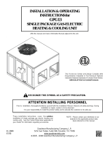
SELECTING THE BLOWER OFF DELAY
In the heating mode, the blower off delay can be selected
to obtain a 90, 120 or 150 seconds period. This can be
accomplished by changing the position of a plastic jumper
located on the ignition control. See the drawing below for
the location of this jumper.
The control is factory set to give a (150) second blower off
delay. See drawing below for the jumper position for all
available settings:
Notes:
• If the jumper is removed, the control will default to a
(150) second blower off delay in the heating mode.
• The blower on time in the heating mode is (30)
seconds and is non-adjustable.
• The blower on time in the cooling mode is (7) seconds
and is non-adjustable.
• The blower off delay in the cooling mode is (60)
seconds and is non-adjustable.
• Caution is to be exercised not to bend the metal pins
when changing the time delay from the factory setting.
STATUS
90
120
150
P3
JUMPER SET
STATUS
90
120
150
P3
JUMPER SET
STATUS
90
120
150
P3
JUMPER SET
FOR 90 SEC.
FOR 120 SEC.
FOR 150 SEC.
BLOWER
TIME OFF
JUMPER
90
120
150
STATUS
P3
TWIN
W
G
R
Black
White
24 v. Red
Com. Blue
GND. Blue
TRANSFORMER
115v. Supply
The Emerson logo is a
trademark and a service mark
of Emerson Electric Co.
/