Q-See QS408-803-5 User manual
- Category
- Digital Video Recorders (DVR)
- Type
- User manual

1
H.264 NETWORK DVR
QS Series
User Manual
MODEL QS434
QS464
QS408
QS206
QS4474

2 3
© 2011 Q-See. Reproduction in whole or in part without written permission is prohibited. All
rights reserved. This manual and software and hardware described herein, in whole or in part,
may not be reproduced, translated, or reduced to any machine-readable form without prior
written approval.
Trademarks: All brand names and products are trademarks or registered trademarks of their
respective owners.
Q-See is a registered trademark of DPS, Inc.
Disclaimer: The information in this document is subject to change without notice. The
manufacturer makes no representations or warranties, either express or implied, of any kind
with respect to completeness of its contents.
Manufacturer shall not be liable for any damages whatsoever from misuse of this product.
Thank You for Choosing a Q-See Product!
All of our products are backed by a conditional service warranty covering all hardware for 12
months from the date of purchase. Additionally, our products also come with a free exchange
policy that covers all manufacturing defects for one month from the date of purchase.
Permanent upgrading service is provided for the software and is available at www.Q-See.com.
Be certain to make the most of your warranty by completing the registration form online. In
addition to warranty and technical support benefits, you’ll receive notifications of product
updates along with free downloadable firmware updates for your DVR. Register today at
www.Q-See.com!
Please see the back of this manual for exclusions.
This manual is written for the QS series of DVRs and was accurate at the time it was
completed. However, because of our ongoing effort to constantly improve our products,
additional features and functions may have been added since that time and on-screen
displays may change. We encourage you to visit our website at www.Q-see.com to check for
the latest firmware updates and product announcements.
Throughout the manual we have highlighted warnings and other important information that will
assist you in operating your new system in a safe and trouble-free manner. Please take the
time to read and follow all instructions and pay attention to alerts as shown below:
About this Manual
NOTE! Text in blue boxes with the Information icon offer additional guidance
and explanations about how to make the most out of your system.
IMPORTANT! Red boxes with this icon indicate warnings. To prevent
possible injury or damage to the product, read all warnings before use.
Rev. 2.2 8/1/11

4 5
1. INTRODUCTION 7
Features and Specifications 8
2. INSTALLATION AND CONNECTION 10
QS206 12
QS408 14
QS434 16
QS464 18
QS4474 20
3. CONTROLS 22
3.1 Mouse Control 22
Virtual Keyboard 23
3.2 Remote Control 24
4. BASIC OPERATION 26
4.1 Power On/Off 26
Standby Mode 26
LCD On/Off 26
Shutdown 26
4.2 Shortcut Menu 27
4.3 System Login 27
4.4 Main Menu 28
4.5 Basic Settings 29
Language 29
Date/Time 30
Password 31
Display 32
Video/Audio 33
4.6 Hard Drive (HDD) Management 34
Formatting the Internal Hard Drive 34
4.7 Playback 35
Video Search 35
File List 36
Using the On-Screen Playback Controls 37
4.8 Backup 38
Using the Playback Software 39
5. RECORDING 42
5.1 Recording Configuration 42
5.2 Recording Schedule 43
5.3 Mask Field 44
5.4 Motion Detect 45
6. ADVANCED FEATURES 46
6.1 Alarm 47
6.2 Email Setup 48
6.3 System Info 49
6.4 System 49
Restoring Factory Settings 50
Restarting the DVR (Soft-Reset) 50
Upgrading the Firmware 50
6.5 Pan-Tilt-Zoom Cameras (PTZ) 51
7. HARD DRIVE INSTALLATION 52
APPENDIX 53
Product Specifications 53
Frequently Asked Questions 55
Q-SEE PRODUCT WARRANTY 59
Questions or Comments? Contact Us 60
TABLE OF CONTENTS

6 7
To prevent damage to your Q-See product or injury to yourself or to others, read and
understand the following safety precautions in their entirety before installing or using this
equipment. Keep these safety instructions where all those who use the product will read them.
nCheck the unit and any accessories included in the package immediately after opening. If
items are missing or damaged, repackage and return to the point of purchase.
n
Use the proper power source. Only use the power adapter supplied with your system. Do
not use this product with a power source that applies more than the specified voltage (100-
240V AC).
nNever insert anything metallic into the DVR. Inserting anything into the DVR or its case can
be a source of dangerous electric shock.
nDo not operate in dusty areas.
nDo not expose this product to rain or use near water. If this product accidentally gets wet,
unplug it and contact an authorized dealer immediately.
nKeep product surfaces clean and dry. To clean the outside case of the DVR, gently wipe
using a lightly dampened cloth (only use water, do not use solvents).
nDo not operate this DVR without the cover securely in place. Do not attempt to do any
repairs to the DVR yourself. If there are unusual sounds or smells coming from the DVR,
unplug it immediately and contact Q-See technical support. Under no circumstances
should the cover be removed while the device is connected to a power source. You should
only remove the cover to install/replace the hard disk drive (See Chapter 7) or replace the
standard 3v lithium cell battery on the motherboard. These are the only user serviceable
parts. You may need to replace the battery if the internal clock resets itself after a power
outage
nHandle DVR box carefully. If you accidentally drop your DVR on any hard surface, it may
cause a malfunction. If the DVR doesn’t work properly due to physical damage, contact an
authorized dealer for repair or exchange.
nMake sure there is proper air circulation around the unit. This DVR system uses a hard drive
for video storage which generates heat during operation. Do not block air holes located on
the bottom, top, sides and back of the DVR as they are designed to keep the system cool
while running. Install or place this product in an area where there is ample air circulation.
nProvide proper ventilation. This DVR has a built-in fan that properly ventilates the system.
Do not cover or impede this fan.
INTRODUCTION
CHAPTER 1
WARNING! ELECTRIC SHOCK RISK!

8 9
FEATURES AND SPECIFICATIONS
This product offers the following features:
Smartphone Compatible
Access live footage directly from your iPhone, iPad or smartphones running Windows Mobile,
Android, Symbian or BlackBerry operating systems. Your DVR can also be set to e-mail your
hand held-device whenever specific activity occurs, such as motion detection.
View Your Video Feed Online with No Extra Service Fees
View your DVR’s live or recorded video footage on any Internet accessible computer with
Internet Explorer, Mozilla Firefox and Google Chrome (using IE plug-in).
Stay Notified with Customizable Email Alerts
Set your system up to notify you when an event has occurred at the location you are
monitoring. Notification alerts can easily be adjusted to your specifications.
Advanced Motion Detection Activated Recording
Advanced motion detection settings ensure that false alarms are not triggered. The easy to
use motion detect set up screen allows you to mask out certain areas which experience heavy
movement in order to avoid false alarms and avoid unnecessary record triggering.
Multiple Backup Options
A built-in USB port gives you the option of backing up and transferring your video footage
using a flash drive or external USB hard drive. You can also connect to an external CD/
DVD writer to burn your file footage right onto a compact disc or DVD disc. Files can also be
accessed from your DVR system to a remote computer location by logging on remotely.
Connect to a TV or PC Monitor Easily
This system comes with both a VGA and BNC out port to allow you to connect to a TV or
computer monitor for viewing purposes.
User-Friendly LCD Control Functions
Front panel button control allows instant booting up and system standby at the press of a
button. LCD monitor can be set to go into energy efficient stand-by mode.
Included Mouse and Remote Control
In addition to front panel button controls, system can also be booted up and put into standby
mode using the included remote control or mouse.
Storage Function
Encrypted file format to ensure data security and avoid vicious data modification.
Compression Format
Supports multiple-channel audio and video. Independent hardware decodes the audio and
video signal from each channel to maintain video and audio synchronization.
Audio Recording
Up to eight channels of audio recording capability depending on model.
24/7 Scheduled Recording
Choose which days of the week and hours of the day you want to set your DVR to record or
not record.
Multiple Playback Options and Advanced Search Functions
Supports real-time recording on each channel independently. Search through recorded files
while you are playing live footage, monitoring through a remote location using a supported
internet browsing application and backing up system files. A variety of playback modes
include: slow play, fast play, and backward play.
Network Monitoring
Supports network remote real-time monitoring (available bandwidth permitting), remote record
search and remote PTZ control.
Alarm Activation Function
Several relay alarm outputs enable you to pair your system with an on-site alarm system.
Communication Ports
s RS485 port can be used for PTZ camera control.
s Standard Ethernet port allows you to access the DVR from a network or the Internet.
PTZ camera control
s Supports PTZ decoder via RS485.
s Supports the PelcoD and PelcoP protocols.
NOTE! Depending on your point of purchase, your DVR may have the hard
disk drive already installed. If your drive was packaged separately, or if you
wish to upgrade your installed drive up to a 1 Terabyte (QS434 and QS408) or
a 2 Terabyte (QS206) drive, please see Chapter 7 at the back of this manual
which covers installing the drive.

10 11
Both displays may be used at the same time, however they will both show the same images
and they cannot be combined. The mouse cursor will only appear on one screen at a time and
this may be selected by rolling the mouse scroll wheel forward (VGA) or backwards (television).
The second display may be used as a “Spot” monitor in a location away from the DVR to allow
another person to view, but not control, the system.
INSTALLATION AND
CONNECTION
CHAPTER 2
IMPORTANT! The default resolution of this DVR is 1024 x 768 pixels. Some
monitors smaller than 19” may not display video properly.
Please note that it is important to keep in mind common safety guidelines when installing your
DVR or connecting additional devices – including turning off and unplugging your DVR before
installing internal components.
POWER
The DVR’s power supply plugs into the DC power socket on the back of the DVR. It is
absolutely essential that you only use the power supply that came with the DVR to ensure
proper operation and to avoid damage.
We also recommend that you use an uninterrupted power supply (UPS) so that the system will
continue to operate in the event of a power loss. In addition, you should connect the DVR into
a UL-1449 rated surge protector. It should have a joule rating of at least 400, a response time
of 10 nanoseconds or less and a clamping voltage of no more than 330 volts.
Some models feature a power switch on the rear panel, while all models have a soft power
switch on the front. For those models with a rear panel power switch, it must be flipped to the
On position to start the DVR. The other models will power up as soon as they are plugged in.
When shutting down the DVR, it is essential that you do so by pressing and holding the soft
power switch on the front until the DVR enters standby mode. Once the display goes blank,
you may either flip the rear power switch to Off or unplug the DVR.
If you wish to restart the DVR from standby mode, then you may do so by pressing and
holding the soft power switch again.
USB PORTS
With the exception of the Model QS464, the port on the front of the DVR is reserved for
external USB drives - whether to back up saved files or to install a firmware upgrade. The
USB mouse should be plugged into the port on the back of the DVR. The QS464 has dual
USB ports on the front panel with the upper port used for the external drive and the lower port
available for use by the mouse. The QS464 features a third USB port on the rear panel for use
by the mouse should you prefer.
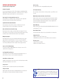
VIDEO DISPLAY
The DVR can output video to either a
standard VGA monitor or television. The
monitor is connected via a VGA monitor cable
(not included) to the VGA port on the rear of
the DVR. The QS4474 does not include a
VGA port. The television is connected to the
BNC Video Out port on the DVR’s back panel
through the use of the included BNC (Male)
to RCA (Female) adapter cable (Picture 2-1)
which plugs into the RCA Video In port on
the back of the television.
PICTURE 2-1
AUDIO
Depending on the model of your DVR, you can record one or more channels of audio to
accompany your video recording. When there are an equal number of video and audio inputs,
the audio will be recorded on the corresponding channel. On DVRs with only one or two
audio inputs, the audio signal will be recorded on the first channel(s) so you should connect
an audio-capable camera to those channels. Likewise, if you are co-locating a microphone to
capture audio to accompany a camera’s video signal, then the camera should be connected
into the first channel or channels.
Also depending upon your model, the audio
connection ports will either be BNC (like the
video ports) or RCA. Microphones, such as
Q-See’s QSPMIC (Picture 2-2) generally
have RCA connectors. If your DVR has RCA
audio inputs, then these will connect directly
to the DVR. For those models with the BNC
connectors, you will need to use a BNC (Male
to RCA (Female) adapter cable shown in
Picture 2-1.
For output, most readily available speakers,
such as those used in audio systems will
have an RCA connector. The QS4474 has a
built-in internal speaker.
The connections and ports of the various models are presented on the following pages.

12 13
1
2
3
4
5
VGA
USB
AUDIO IN CVBS OUTAUDIO
OUT
VIDEO IN
1
GND
COM1
NO1
COM2
NO2
GND
485A-2
485B-2
GND
485A-1
485B-1
GND
+12V
GND
2 3 4 5 6 7 8 9 10 11 12 13 14
16 15
ALM IN
RJ45
DC +12V
IN
2
1
3 4 5 6 87 9
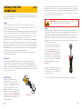
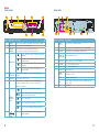
Item #
Connector Description
1 VIDEO IN Video input for connecting analog video signal input (BNC)
2
DC 12V/3A Power Connection
3 VGA OUTPUT To connect to VGA monitor
4 NETWORK For connecting Ethernet cable
5 USB Mouse port
6
ALARM INPUT 8 I/O Alarm input
ALARM
OUTPUT
I/O Output for alarm
RS485 RS485 for connecting PTZ
+12V
Power supply for DC relay, the current is 100MA (to prevent
short circuits)
7 AUDIO IN Audio input for connecting audio signal (2 feeds)
8
AUDIO
OUTPUT
For connection to amplified speaker
9 VIDEO OUT Video output for connecting TV (BNC)
Item # Name/ Symbol Description
1 STANDBY Press to set the system in standby mode. Press again to wake.
2 MENU/EXIT Press to open/close the main menu.
3 CHANNEL/
NUMBERS
Press the number buttons to view the selected channel full-
screen; press buttons 1-0 to input passwords and user IDs.
4
NAVIGATION
▲
Press to move cursor up; in PTZ mode, press to pan
camera up.
▼
Press to move cursor down; in PTZ mode, press to
pan camera down.
◄
Press to move cursor left; in PTZ mode, press to pan
camera left.
►
Press to move cursor right; in PTZ mode, press to
pan camera right.
5 LED
INDICATORS
Shows status of hard drive, recording, alarm, HDD full and
network.
6 IR SENSOR IR Receiver for remote control.
7
OK
In menus, press to confirm selections; in PTZ mode, press to
change the navigation buttons to control a connected PTZ
camera (not included)
8
DURING
PLAYBACK
PRESS:
◄ ◄
Increase reverse playback speed 1X, 2X, 4X.
n
/
►
Press to freeze playback to one frame, then press
again to advance frame-by-frame.
►
Press to start playback
► ►
|
Press to slow playback speed by 1/2, 1/4, 1/8.
► ►
Press to increase forward playback speed 1X, 2X,
4X.
9
USB Connect a USB flash drive for data backup and
firmware upgrades
QS206
FRONT PANEL
HDD REC ALM FULL NET
OK
MENU
EXIT
1 2 3 4 5
6 7 8 9 0
QS206
16CH H.264 Digital Video Recorder
21 4 63 5
7 8 9
REAR PANEL

14 15
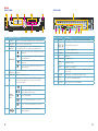
Item #
Connector Description
1 Power Switch Power On/Off
2 USB Mouse port
3 AUDIO IN Audio input for connecting audio signal (8 feeds)
4
AUDIO
OUTPUT
For connection to amplified speaker
5 VIDEO IN Video input for connecting analog video signal input (BNC)
6
DC 12V/3A Power Connection
7 NETWORK For connecting Ethernet cable
8 VGA OUTPUT To connect to VGA monitor
9 VIDEO OUT Video output for connecting TV (BNC)
10
ALARM INPUT 8 I/O Alarm input
ALARM
OUTPUT
I/O Output for alarm
RS485 RS485 for connecting PTZ
+12V
Power supply for DC relay, the current is 100MA (to prevent
short circuits)
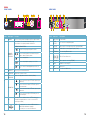
QS408
FRONT PANEL
REAR PANEL
1
2
3
4
5
6
7
8
VGA
USB
AUDIO IN AUDIO VIDEO IN
VIDEO
OUT
1 3 5 7
2 4 6 8
1 3 5 7
2 4 6 8
GND
+12V
485B
485A
GND
NO
COM
GND
ALARM IN
RJ45
ON/OFF
DC +12V
IN
-
+
2 41 3
6 8 107 9
5
HDD REC ALM FULL NET
OK
1
4
7
QS408
MENU
EXIT
2 3
5 6
8 9 0
1
3
54
8
6
7 9
2
Item # Name/ Symbol Description
1 STANDBY Press to set the system in standby mode. Press again to wake.
2 LED
INDICATORS
Shows status of hard drive, recording, alarm, HDD full and
network.
3
NAVIGATION
▲
Press to move cursor up; in PTZ mode, press to pan
camera up.
▼
Press to move cursor down; in PTZ mode, press to
pan camera down.
◄
Press to move cursor left; in PTZ mode, press to pan
camera left.
►
Press to move cursor right; in PTZ mode, press to
pan camera right.
4
DURING
PLAYBACK
PRESS:
◄ ◄
Increase reverse playback speed 1X, 2X, 4X.
n
/
►
Press to freeze playback to one frame, then press
again to advance frame-by-frame.
►
Press to start playback
► ►
|
Press to slow playback speed by 1/2, 1/4, 1/8.
► ►
Press to increase forward playback speed 1X, 2X,
4X.
5 IR SENSOR IR Receiver for remote control.
6 MENU/EXIT Press to open/close the main menu.
7
CHANNEL/
NUMBERS
Press buttons 1-8 to view that channel full-screen
Press buttons 1-0 (“0” is located next to the playback buttons) to
input passwords and user IDs.
7
OK
In menus, press to confirm selections; in PTZ mode, press to
change the navigation buttons to control a connected PTZ
camera (not included)
9
USB Connect a USB flash drive for data backup and
firmware upgrades

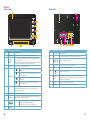
16 17
1
2
3
4
VGA
USB
1
+5V
GND
485B
485A
GND
1NO
1COM
GND
3
2 4
1 3
2 4
ALM IN
RJ45
DC +19V
IN
AUDIO INAUDIO OUT
VIDEO OUT
VIDEO IN
-
+
1 2
5
4
6 87 9
3
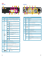
Item #
Connector Description
1
AUDIO
OUTPUT
For connection to amplified speaker
2 VIDEO IN Video input for connecting analog video signal input (BNC)
3 AUDIO IN Audio input for connecting audio signal (4 feeds)
4
DC 19V Power Connection
5 VIDEO OUT Video output for connecting TV (BNC)
6 NETWORK For connecting Ethernet cable
7 VGA OUTPUT To connect to VGA monitor
8
ALARM INPUT 8 I/O Alarm input
ALARM
OUTPUT
I/O Output for alarm
RS485 RS485 for connecting PTZ
+12V
Power supply for DC relay, the current is 100MA (to prevent
short circuits)
9 USB Mouse port
Item # Name/ Symbol Description
1 STANDBY Press to set the system in standby mode. Press again to wake.
2 MENU/EXIT Press to open/close the main menu.
3
CHANNEL/
NUMBERS
Press buttons 1-4 to view that channel full-screen
Press buttons 1-0 to input passwords and user IDs.
4
NAVIGATION
▲
Press to move cursor up; in PTZ mode, press to pan
camera up.
▼
Press to move cursor down; in PTZ mode, press to
pan camera down.
◄
Press to move cursor left; in PTZ mode, press to pan
camera left.
►
Press to move cursor right; in PTZ mode, press to
pan camera right.
5 LED
INDICATORS
Shows status of hard drive, recording, alarm, HDD full and
network.
6 IR SENSOR IR Receiver for remote control.
7
OK
In menus, press to confirm selections; in PTZ mode, press to
change the navigation buttons to control a connected PTZ
camera (not included)
8
DURING
PLAYBACK
PRESS:
◄ ◄
Increase reverse playback speed 1X, 2X, 4X.
n
/
►
Press to freeze playback to one frame, then press
again to advance frame-by-frame.
►
Press to start playback
► ►
|
Press to slow playback speed by 1/2, 1/4, 1/8.
► ►
Press to increase forward playback speed 1X, 2X,
4X.
9
USB Connect a USB flash drive for data backup and
firmware upgrades
HDD REC ALM FULL NET
OK
MENU
EXIT
1 2 3 4 5
6 7 8 9 0
21 4 63 5
7 8 9
QS434
FRONT PANEL
REAR PANEL

18 19
VGA
1
485A
485B
3
2 4
1
2
RJ45
DC +12V
IN
AUDIO INAUDIO OUT
VIDEO OUT
VIDEO IN
-
+
ON/OFF
1 2 4
7
6
8
109
3 5
Item #
Connector Description
1 Power Switch Power On/Off
2
AUDIO
OUTPUT
For connection to amplified speaker
3 VIDEO IN Video input for connecting analog video signal input (BNC)
4 AUDIO IN Audio input for connecting audio signal (2 feeds)
5 NETWORK For connecting Ethernet cable
6
DC 12V Power Connection
7 VIDEO OUT Video output for connecting TV (BNC)
8 RS485 RS485 for connecting PTZ
9 USB Mouse port
10 VGA OUTPUT To connect to VGA monitor
Item # Name/ Symbol Description
1 STANDBY Press to set the system in standby mode. Press again to wake.
2
CHANNEL/
NUMBERS/
PLAYBACK
Press buttons 1-4 to view that channel full-screen
Press buttons 1-0 to input passwords and user IDs.
DURING PLAYBACK PRESS:
◄ ◄
Increase reverse playback speed 1X, 2X, 4X.
n
/
►
Press to freeze playback to one frame, then press
again to advance frame-by-frame.
►
Press to start playback
► ►
|
Press to slow playback speed by 1/2, 1/4, 1/8.
► ►
Press to increase forward playback speed 1X, 2X,
4X.
3 MENU/EXIT Press to open/close the main menu.
4 IR SENSOR IR Receiver for remote control.
5 LED
INDICATORS
Shows recording status and motion detection (Alarm).
6
NAVIGATION
▲
Press to move cursor up; in PTZ mode, press to pan
camera up.
▼
Press to move cursor down; in PTZ mode, press to
pan camera down.
◄
Press to move cursor left; in PTZ mode, press to pan
camera left.
►
Press to move cursor right; in PTZ mode, press to
pan camera right.
7
OK
In menus, press to confirm selections; in PTZ mode, press to
change the navigation buttons to control a connected PTZ
camera (not included)
8
USB The upper port is to connect a USB flash drive for
data backup and firmware upgrades.
The lower port is to connect a USB mouse.
QS464
1 2 3 4 5
6 7 8 9 0
MENU
EXIT
OK
21 4 863 5 7
REC ALARM
USB 2.0
USB MOUSE
QS464
FRONT PANEL
REAR PANEL

20 21
Item #
Connector Description
1 Power Switch Power On/Off
2 FAN Cooling fan exhaust port. This should not be blocked.
3
DC 12V Power Connection
4 VIDEO IN BNC connectors for up to four cameras
5 RJ45 For connecting Ethernet cable
6
USB port for the mouse
7
AUDIO
PORTS
BNC ports. Input for a single audio channel. Output to an
external speaker. Connecting an external speaker will not affect
the DVR’s internal speaker.
8 RS485 RS485 for connecting PTZ camera
9 VIDEO OUT Video output for connecting to a TV (BNC)
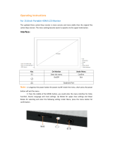
Item # Name/ Symbol Description
1 SCREEN 7” LCD screen
2 LCD ON/OFF Turns the screen on or off. The DVR will still operate.
3
STANDBY/
DISPLAY
MODE
Pressing and holding will bring up the menu to put the DVR to
sleep or turn it off.
Pressing and releasing the button will cycle through the individual
channels or display all four channels simultaneously.
4 MENU/EXIT Press to open/close the main menu.
5
NAVIGATION
▲
Press to move cursor up; in PTZ mode, press to pan
camera up.
▼
Press to move cursor down; in PTZ mode, press to
pan camera down.
◄
Press to move cursor left; in PTZ mode, press to pan
camera left.
►
Press to move cursor right; in PTZ mode, press to
pan camera right.
6
OK
In menus, press to confirm selections; in PTZ mode, press to
change the navigation buttons to control a connected PTZ
camera (not included)
7 IR SENSOR IR Receiver for remote control.
8 LED
INDICATORS
Shows power, recording status, motion detection (Alarm), hard
drive and network connection status
9
USB The upper port is to connect a USB flash drive for
data backup and firmware upgrades.
The lower port is to connect a USB mouse.
SPEAKER
QS4474
FRONT PANEL
REAR PANEL
HDD NETALMREC
Standby
POWER
LCD
ON/OFF
MENU
EXIT
OK
QS4474
1
2
3
7 9
8
4
6
5
RS485-A
RS485-B
GND
DC +12V
IN
RJ45
1 2 3 4
IN OUT
VIDEO IN AUDIO
ON OFF
-
+
VIDEO OUT
1 2
3 5 7 94 6 8

22 23
CHAPTER 3 CONTROLS
CLICK-AND-DRAG Select motion detection zone
Select privacy mask zone
SCROLL WHEEL Scroll forward to select VGA monitor
Scroll backwards to switch to TV/RCA monitor
This DVR can be controlled through the USB mouse or with the remote control. We have
found that the majority of our customers prefer to operate their DVRs using the USB mouse
because of its ease of use and flexibility and our manual is set up with this in mind. For your
convenience, we also include a remote control which allows you to perform most of the
day-to-day functions from a distance. It functions as a typical remote control with additional
buttons allowing you to navigate through menus and control functions. We recommend that
you configure your DVR using the mouse controls, reserving the remote control for operations
such as live viewing, file search and playback. For the purposes of this manual, instructions
will be given for using the mouse but the other modes are also presented in this chapter.
3.1 MOUSE CONTROL
The mouse operates in a manner similar to how it is used on a conventional computer; point-
and-click, right-click, double click and so on. How these functions are used is based on the
context of where they are used. Some examples are:
LEFT CLICK: Selecting an item
Opening a menu
Checking a box or motion detection status
Selecting letters, numbers or symbols on the virtual keyboard.
DOUBLE CLICK: Selecting an event for playback
Selecting a screen to zoom into from multi-screen mode
CONTROLS
CHAPTER 3
PICTURE 3-1
VIRTUAL KEYBOARD
The virtual keyboard is contextual. For example, it will only show digits when the field is for
numeral entries. In fields where letters and symbols can be entered, users can switch between
various formats – numbers, upper case, lower case and symbols – by selecting the blue tab in
the upper right corner of the keyboard.
Available keyboards include:
PICTURE 3-2
RIGHT CLICK
Exits any window. Exits
any menu or reopens
previous menu.
Opens Pop-Up
Shortcut Menu
M A I N M E N U
K E Y L O C K
C H N S W I T C H
D I G I T A L Z O O M
V I D E O S E A R C H
P T Z
M U T E
M A N U A L R E C
S T O P R E C
R O T A T I O N
The keyboards are used by clicking on the desired character. Characters are deleted with the
key. To finish entering your text, click the key. Clicking outside of the keyboard will
close it.
NUMBERS
UPPER CASE
LETTERS
LOWER CASE
LETTERS
a b c d e f g abc
h i j k l m n
o p q r s t u
v w x y z
1 2 3 4 123
5 6 7 8
9 0
A B C D E F G ABC
H I J K L M N
O P Q R S T U
V W X Y Z

24 25
CHAPTER 3 CONTROLS
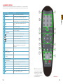
3.2 REMOTE CONTROL
The buttons on the Remote Control operate in the same manner as on a conventional DVR
remote. Some buttons have multiple functions depending on which menu is being accessed.
PICTURE 3-3
# Name/Symbol Function
1 STANDBY Press to turn standby mode ON/OFF.
2 LOGIN/LOCK If “Security” has been enabled in the Setup menu,
press to open the user password login screen.
3 Number/Channel buttons While in menus, press buttons 0~9 to enter values;
during live viewing, press to view channels full-screen.
4
Press to switch between quad and full-screen
displays.
5 MENU Opens the main menu.
6 PTZ Press to open the PTZ control window.
7 EXIT Close menu windows.
8 Navigation/OK:
/CH+
Move cursor in menus up; Channel Up.
/FWD
Move cursor in menus to the right
/REW
Move cursor in menus left
/CH-
Move cursor in menus down; Channel down.
OK In menus, press to confirm selections; during
playback and preview, press to view system
information
9 +/ - : In menus, press to
adjust values.
10 RECORD: Press to start
manual recording.
11 STOP: Press to stop manual
recording.
12 EXTRA: For future use.
13 Playback controls:
Increase reverse playback speed 2X, 4X, 8X
Press to start playback
Press to increase forward playback speed 2X, 4X, 8X
Press to slow playback speed by 1/2, 1/4, 1/8
Press to freeze playback to one frame, then press
again to advance frame-by-frame
TIP: When using the remote
control to enter password and
camera titles, select the field
using the navigation buttons,
press ENTER, and then press
the number buttons.

26 27
CHAPTER 4 BASIC OPERATION
BASIC OPERATION
CHAPTER 4
This chapter is intended to help you get your DVR up and running before you activate any
advanced features which are covered in later chapters. You can use the mouse, remote
control and the buttons on the front of the DVR to operate your system, but for convenience,
we will be discussing operations using the mouse.
4.1 POWER ON/OFF
Connect the power cable to the DC power port on the rear panel. If your DVR has a power
switch on the rear channel you will need to flip it to the “On” position. If the DVR is not
equipped with a power switch, it will power up when connected to a power source.
At startup, the system performs a basic system check and runs an initial loading sequence.
After a few moments, the system loads a live display view.
STANDBY MODE
The system can be put into Standby Mode. Power will remain to the system but will not be
recording. You may put your system into Standby Mode by one of two methods:
To Start Standby Mode:
Press and hold the POWER or STANDBY (depending on model) button on the front
panel or remote control until the prompt closes. The system enters standby mode.
Select “Standby” in the pop-up Shortcut menu (described in the next section)
To Wake Up from Standby Mode:
Press and hold the POWER button on the front panel or remote control until the system
beeps. The system will begin powering up.
LCD ON/OFF
On the QS4474, you can turn the LCD monitor off while allowing the DVR to continue to
operate. Simply press and release the LCD ON/OFF button to the right of the LCD screen.
Pressing it again will turn the LCD back on.
SHUTDOWN
When the DVR will not be in use for an extended period of time, it is recommended that you
shut it down completely. To do so, follow the above instructions to put the DVR into Standby
mode. Once the DVR has gone into hibernation, turn off the power switch (if present) and then
disconnect it from its power source - preferably by turning off the surge protector that it is
plugged into.
PICTURE 4-1
M A I N M E N U
K E Y L O C K
C H N S W I T C H
D I G I T A L Z O O M
V I D E O S E A R C H
P T Z
M U T E
M A N U A L R E C
S T O P R E C
R O T A T I O N
MULTIPICTURE: Choose multi-screen mode
PTZ: Opens the PTZ control menu
VIDEO SEARCH: Open the Search Menu to
view recorded video
MUTE: Mute listen-in audio on the system
START RECORD: Start manual recording
STOP RECORD: Stop manual recording
START CRUISE: Activates preset PTZ cruise
STANDBY: Click to go into standby mode
ROTATION: Start full screen cycle through
channels
To close the Shortcut menu, click anywhere on screen.
4.2 SHORTCUT MENU
The Shortcut menu gives direct access to many of the system’s functions, features and
options without having to go through a series of intermediiate steps.
Right-clicking with the mouse anywhere on the screen will bring up the Shortcut menu.
MAIN MENU: Opens the main system menu
IMPORTANT! To protect your system, you should always power down the
DVR as described above before unplugging it or using the power switch.
PICTURE 4-2
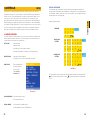
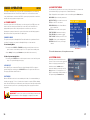
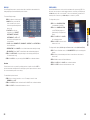
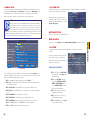
4.3 SYSTEM LOGIN
By default, passwords are disabled on the
system. You do not need to enter a password
when accessing any system menus. The
default user name is admin and the
password is blank (no password). Just click
Apply However, for security purposes, it is
highly recommended to enable passwords on
the system using the Password menu.

28 29
CHAPTER 4 BASIC OPERATION
PICTURE 4-3
PICTURE 4-4
PICTURE 4-5
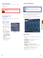
4.4 MAIN MENU
To access the Main Menu, right-click anywhere onscreen with the mouse to open the
Shortcut menu and select MAIN MENU. Pressing the Menu or MENU/EXIT button on the
remote control or front panel of the DVRm, respectively, will also open the Main Menu.
*Audio capable cameras or powered microphones (not included) are required for audio
recording on the system.
Symbol Name Function
SEARCH Search for recorded video on the system.
RECORD Configure recording parameters (quality, resolution), set record
modes, and enable/disable audio recording.*
HDD Display hard drive status and format the internal hard drive of the
system.
BASIC Open the Basic Setup Menu, which lets you set the system
language, date and time, Device IDs and passwords, and configure
audio and video settings.
ADVANCE Opens the Advanced Setup Menu, which lets you view system
info, configure alarm, PTZ, mobile, and network settings.
EXIT Closes the Main Menu.
Placing the mouse over an icon will display
iinformation about its contents and/or
function.
4.5 BASIC SETTINGS
Set the system language, date and time, passwords, and configure audio and display
options.
The Basic Setup menu contains the following
submenus: Language, Date/Time,
Password, Display, and Video/Audio.
LANGUAGE
English is the only language available at this
time.
IMPORTANT! After changing the Video Format, the device will need to be
restarted.

30 31
CHAPTER 4 BASIC OPERATION
PICTURE 4-6
PICTURE 4-7
PICTURE 4-8
PICTURE 4-9
IMPORTANT! Date and time should be properly set before continuing so that
you can easily locate recorded events. Inaccurate dates and times on files may
affect their admissibility as evidence.
DATE/TIME
To set the date and time:
STEP 1. Click DATE/TIME and configure
the following options:
• DATE: Enter the day, month, and year.
• DATE FORMAT: Select DD/MM/YYYY,
MM/DD/YYYY, or YYYY/MM/DD
• TIME: Enter the time
• TIME FORMAT: Use the drop-down
menu and select 12 HOURS or 24
HOURS
• DST: Use the drop-down menu to
select ON/OFF to enable/disable
Daylight Savings Time
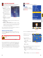
PASSWORD
When you first startup your system, you are automatically logged in as the ADMIN under
Device ID000000. By default, passwords are disabled on the system. You will not need a
password to log in or access menus. You will not need a password to access your system
using the browser-based remote software.
The system employs two levels of user authorities connected to a Device ID. The authorities
are as follows:
• ADMIN (administrator): Has full control of the system, and can change both administrator
and user passwords and enable/disable password checking
• USER (normal user): Only has access to live viewing, search, playback, and other limited
authorities.
For security reasons, it is highly recommended to enable passwords on your system. If you
enable passwords, you must select a 6-digit ADMIN password and a 6-digit USER password.
The QS434 and QS464 only support one Admin and one User account.
• ZONE: Select the correct time zone based on your current location. If you are uncertain
of your time zone, you can find it at http://www.worldtimezone.com
STEP 2. Click MODIFY DATE AND TIME. Click CLOSE in the confirmation window.
STEP 3. Click APPLY. The new date and time are saved.
Daylight Savings Time
To set daylight savings time:
STEP 1. Under DST, select ON. DST options appear.
STEP 2. Under DST MODE select one of the following:
• CUSTOM: Set customized start and end times for DST (go to step 4)
• DEFAULT: The Default setting will apply DST from the second Sunday of March to the
second Sunday in November (Go to step 3)
• If using the DEFAULT, click APPLY.
• If setting a CUSTOM DST, use the drop-down menus to select a week and month for
the start and end times.
STEP 3. Click APPLY. Click CLOSE in the confirmation window.
STEP 4. Click EXIT in each menu until all windows are closed. Type date via numeric key.
You can change the Device ID and password
of the ADMIN and the USER from the
Password menu.
To open the Password/Security menu, click
on Basic in the Main Menu and then select
Password.
To change your Device ID and Password:
STEP 1. Click the field beside Device ID
and enter a 6-digit numerical Device
ID using the Virtual Keyboard. For
example: changing the ID to 000010.
STEP 2. Under Password, select
ENABLE.
STEP 3. Click the field beside Admin
Password to enter a 6-digit
numerical password using the Virtual
Keyboard. Re-enter the password in
the corresponding field.
STEP 4. Click the field beside User
Password to enter a 6-digit
numerical password using the Virtual
Keyboard. Re-enter the password in
the corresponding field.
The ADMIN and USER passwords must
not be the same.
STEP 5. Click Apply to save your
changes. Click Close in the
confirmation window.
STEP 6. Click Exit in each menu until all
windows are closed.

32 33
CHAPTER 4 BASIC OPERATION
DISPLAY
Use the Display Setup menu to customize channel titles, show/hide the date and time in live
viewing and playback, and enable/disable preview channels.
PICTURE 4-10
PICTURE 4-11
To customize Display settings:
STEP 1. Configure the following options:
• NAME: Click any of the fields and
enter a new title for the selected
channel using the Virtual Keyboard
(mouse only)
• POSITION: Reposition the
channel title; select TOPLEFT,
BOTTOMLEFT, TOPRIGHT,
BOTTOMRIGHT, or OFF. If OFF,
the title will not be displayed for the
selected channel
• COLOR: Adjust CHROMATICITY, LUMINOSITY, CONTRAST, and SATURATION for
the selected channel
• PREVIEW TIME: Select ON/OFF to show/ hide the date and time during live viewing
• RECORD TIME: Select ON/OFF to show/hide the date and time during playback.
STEP 2. Click NEXT PAGE to change the settings for the remaining channels (8 and
16-channel models only).
STEP 3. Click APPLY to save your settings. Click CLOSE in the confirmation window.
Preview
Preview channels can be very useful if your display monitor is in public view. Select OFF for
preview channel and it will appear black on the display to give the impression that no cameras
are connected and the system is not recording.
To enable/disable preview channels:
STEP 1. Choose a channel you wish to conceal. For example, channel 3. Under
PREVIEW, select OFF.
STEP 2. Click APPLY. Channel 3 will turn black. Click CLOSE in the confirmation window.
STEP 3. Click EXIT in all menus until all windows are closed.
VIDEO/AUDIO
Use the Video/Audio menu to set the resolution and camera video system on the DVR. You
will need to have microphones or audio-equipped cameras connected to your DVR (through
the Audio In ports) in order to record sound. To listen to recorded audio, you must have an
external speaker connected to your Audio Out port on the back of your DVR.
To configure video options:
STEP 1. Under VGA RESOLUTION,
select 800x600 or 1024x768.
STEP 2. Under CAMERA SYSTEM,
select NTSC (North and most of
South America) or PAL (Brazil and
Europe).
STEP 3. Click APPLY. Click CLOSE in
the confirmation window.
STEP 4. Click EXIT in all menus until all
windows are closed.
To configure audio options (Available only on Channels 1 and 2 on the QS464 and QS206):
STEP 1. From the Video/Audio menu, click VOLUME SETUP. A split-screen display view
appears.
STEP 2. Click any channel and adjust the slider to increase/decrease the volume for
listen-in audio.
STEP 3. Click X to return to the Video/Audio menu.
STEP 4. Click APPLY. Click CLOSE in the confirmation window.
STEP 5. Click EXIT in all menus until all windows are closed.

34 35
CHAPTER 4 BASIC OPERATION
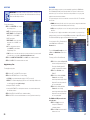
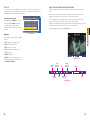
4.7 PLAYBACK
View recorded video on the system through the Search menu.
PICTURE 4-13
PICTURE 4-13
M A I N M E N U
K E Y L O C K
C H N S W I T C H
D I G I T A L Z O O M
V I D E O S E A R C H
P T Z
M U T E
M A N U A L R E C
S T O P R E C
R O T A T I O N
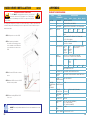
VIDEO SEARCH
Select VIDEO SEARCH in the Shortcut
Menu (Picture 4-13) or select it in the Main
Menu (Picture 4-14).
Click PLAY to play back the last minute of
recorded video (Quick Search).
To search for a particular event:
STEP 1. Select a specific channel to
view or select All.
STEP 2. Enter a date using the Virtual
Keyboard
STEP 3. Click Search
PICTURE 4-15
PICTURE 4-12
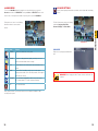
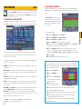
4.6 HARD DRIVE (HDD) MANAGEMENT
This window displays essential information about the system’s internal hard drive,
and lets you format the internal hard drive and external USB flash drive.
The HDD menu displays the following:
• HDD STATUS: The system will display
“OK” for normal operation. This DVR
supports up to a 1TB or 2TB hard
drive depending on the model.
• SIZE: The size (in gigabytes) of the
internal hard drive. The size of your
system`s internal hard drive will vary
by model
• FREE SPACE: The space (in gigabytes)
remaining on the system`s internal
hard drive.
• AVAILABLE TIME: The recording time (in hours) remaining on the HDD based on your
current record settings
• OVERWRITE: Select ENABLE or DISABLE. If Overwrite is enabled prior to recording,
the system will record over the oldest video data once the hard drive is full. If Overwrite
is disabled, the system will stop recording once the hard drive is full and the “FULL”
LED on the front panel of the system will light up.
If there is no hard drive in DVR, or the DVR cannot read the hard drive, or the hard drive is not
formatted, it will display an “H” in the video preview interface.
FORMATTING THE INTERNAL HARD DRIVE
If you installed a new hard drive, you must format the hard drive in the DVR before it can be
used. Clicking on the HDD Format button will begin the formatting process. After formatting,
the system will restart.
CAUTION! Formatting the hard drive erases all video data! This step cannot
be undone!
To install a new hard drive, or to replace a defective one, please see Chapter 7.
Most currently available USB flash drives are compatible with this DVR, however if you need
to reformat your flash drive - say to erase old data - then clicking on the USB Format button
while the drive is connected to the upper USB port on the front of the DVR will allow you to
reformat it. This button is not for use with any external USB hard drive you may connect to
the DVR for backup. External hard drives will need to be formatted using the Fat32 format and
this can be done by connecting the drive to the USB port on a PC and reformatting it from
there.
BASICHDDSEARCH RECORD EXITADVANCE
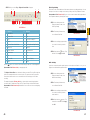
SE A R CH
When you first open the Search menu it will display the current date.
CH N
RE C ORD STA T E
DA T E
EX I T
FI L E L I ST
AL L
JU L .
14 T H
RE C ORD SEA R CH
07 / 14/ 2 011
SE A RCH 0 9 :07 P LAY
00 01 02 03 0 4 05 06 0 7
08 09 10 11 1 2 13 14 1 5
16 17 18 19 2 0 21 22 2 3
01 02 03 04 05 0 6 0 7 0 8 09 10 11 12 13 14 15 16
17 18 19 20 21 2 2 2 3 2 4 25 26 27 28 29 30 31
Recorded events (Alarm and Motion Detection-triggered recordings) appear in red while
scheduled recordings will be shown in green.
STEP 4. Click a date in the Month Grid to select the date of the video.
STEP 5. Click on an hour block to begin playback of the video file(s) recorded during that
period.
or
STEP 6. Select File List to see a list of recorded files. (Shown in Picture 4-16)
1 2 3
4
5
6

36 37
CHAPTER 4 BASIC OPERATION
MUTE
31
CH1
7/25/2011 23:48:25
PICTURE 4-17
PICTURE 4-18
PICTURE 4-16
TY P E
EX I T
BA C K UP
OT H E R
AL L
LA S T
NE X T
PR E
FI R S T
AL L
C H TIM E SIZE TYP E B AK
FI L E LI S T
00 : 0 0:0 0
SE A R CH
01 0 7:5 5 :53 - 0 7:5 7 :17 4. 7 M N o rmal
01 0 7:5 7 :19 - 0 7:5 9 :23 6. 7 M A l arm
01 0 7:5 9 :25 - 0 8:0 0 :33 3. 7 M A l arm
01 0 8:0 0 :36 - 0 8:0 1 :47 3. 8 M A l arm
01 0 8:0 1 :47 - 0 8:0 2 :26 2. 2 M N o rmal
01 0 8:0 2 :26 - 0 8:0 8 :15 18. 3 M A l arm
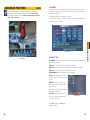
USING THE ON-SCREEN PLAYBACK CONTROLS
The DVR can play back a single channel in full screen or up to four channels in multi-view
mode.
Move the mouse slightly to display the onscreen playback controls. You can also use the
playback control buttons on the remote control or on front panel of the DVR.
The controls operate in the same manner as those found on any VCR, DVR or other video
player. You can play, pause, fast forward, rewind, and slow down playback.
Drag the slider to adjust the volume (You must have had an audio-capable camera connected
to this channel at the time of the event). Select the box to mute the audio.
Click X to quit playback and return to the Search menu.
MUTE
31
Digital
Zoom
Pause
Viewing
Mode
(Click to change)
Volume
Rewind
(2x, 4x, 8x)
Play Exit
Playback
Fast Forward
(2x, 4x, 8x)
Slow
Advance
(1/2, 1/4, 1/8)
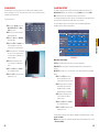
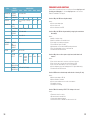
FILE LIST
You can use the File List Shortcut Menu to see a detailed list of all the recorded video on your
system. Clicking on a file will begin playback. In the case of multiple files, you may need to use
the Next button to see another page of recorded files.
To narrow search results:
Under TYPE, select NORMAL to view only
normal recordings, ALARM, to view alarm
recordings (includes alarm and motion
detection), or ALL to view all video on your
system.
Navigation
Use the buttons on the side panel to navigate
the file list:
• FIRST: Jump to the first page of the list
• PRE: Turn to the previous page
• NEXT: Turn to the next page
• LAST: Jump to the last page of the list
• ALL: Select all files
• OTHER: Clear all files
• BACKUP: After selecting a file(s), click to
begin copying the data to a USB flash drive.
See Section 4.8 Backup.

38 39
CHAPTER 4 BASIC OPERATION
STEP 5. Click BACKUP from the side-
panel to immediately begin copying
the files to the USB flash drive.
The download progress will be
displayed in the status window.
PICTURE 4-19
PICTURE 4-20
PICTURE 4-21
PICTURE 4-22
PICTURE 4-23
Backing Up Recorded Data
STEP 1. Connect a blank USB flash
drive to the top USB port on the front
panel of the DVR.
STEP 2. Open the Search menu and
search for recorded data on the
system.
STEP 3. Click FILE LIST.
STEP 4. Select the files you want to
backup and click the BAK box next
to the file name (See Picture 4-19).
Select multiple files if desired. Click
ALL to select all files; click OTHER to
deselect all files.
4.8 BACKUP
Once you have located a recorded video event on your system’s hard drive, you can copy it to
a USB flash drive. Most USB flash drives are compatible with this DVR.
NOTE! The size of each file is shown in the File List menu. Use this to help
you find a USB flash drive large enough to hold all the files you wish to backup.
CAUTION! DO NOT remove the USB flash drive during backup.
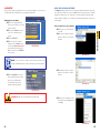
USING THE PLAYBACK SOFTWARE
The Playback software included on the accompanying software disk will play back the video
files created by your DVR. These files have a .264 file extension and will not play on standard
media player software unless you convert them to .avi format using the Playback program.
Install the Playback software to your computer as normal before attempting to view video you
have backed up.
To view a video file on your computer
STEP 1. Copy one or more backup files
to your PC.
STEP 2. Launch the Playback software
and select “Open Local File” from the
File Menu.
STEP 3. Navigate to the file you wish to
play back. It should have a .264 file
extension.
STEP 4. Once you’ve loaded the file into
the program, click the Play menu and
select Play.
TYPE
EXIT
BACKUP
OTHER
ALL
LAST
NEXT
PRE
FIRST
ALL
CH TIME
SIZE TY P E BAK
FILE LIST
00:00:00
SEARCH
01 07:55:53-07:57 : 1 7 4 . 7 M N o r m a l
01 07:57:19-07:59 : 2 3 6 . 7 M A l a r m
01 07:59:25-08:00 : 3 3 3 . 7 M A l a r m
01 08:00:36-08:01 : 4 7 3 . 8 M A l a r m
01 08:01:47-08:02 : 2 6 2 . 2 M N o r m a l
01 08:02:26-08:08 : 1 5 1 8 . 3 M A l a r m
Page is loading ...
Page is loading ...
Page is loading ...
Page is loading ...
Page is loading ...
Page is loading ...
Page is loading ...
Page is loading ...
Page is loading ...
Page is loading ...
Page is loading ...
-
 1
1
-
 2
2
-
 3
3
-
 4
4
-
 5
5
-
 6
6
-
 7
7
-
 8
8
-
 9
9
-
 10
10
-
 11
11
-
 12
12
-
 13
13
-
 14
14
-
 15
15
-
 16
16
-
 17
17
-
 18
18
-
 19
19
-
 20
20
-
 21
21
-
 22
22
-
 23
23
-
 24
24
-
 25
25
-
 26
26
-
 27
27
-
 28
28
-
 29
29
-
 30
30
-
 31
31


Q-See QS408-803-5 User manual
- Category
- Digital Video Recorders (DVR)
- Type
- User manual
Ask a question and I''ll find the answer in the document
Finding information in a document is now easier with AI
Related papers
Other documents
-
itsensor RS485 User guide
-
 WIMAXIT M1560CTV2 User guide
-
NIGHT OWL 4BL-45GB User manual
-
-
-
Sunforce 69019 Operating instructions
-
NIGHT OWL Night Owl User manual
-
-
-
