
UX
UX
880
80
0
Speaker / System Processor
Speaker / System Processor
INPUT CHANNELS
INPUT CHANNELS
OUTPUT CHANNELS
OUTPUT CHANNELS
ETHERNET
ETHERNET
Clip
Clip
Lim
Lim
-12
-12
Sig
Sig
Clip
Clip
Lim
-12
-12
Sig
Sig
Clip
Clip
Lim
Lim
-12
-12
Sig
Sig
Clip
Clip
Lim
Lim
-12
-12
Sig
Sig
Clip
Clip
Lim
Lim
-12
-12
Sig
Sig
Clip
Clip
Lim
Lim
-12
-12
Sig
Sig
Clip
Clip
Lim
Lim
-12
-12
Sig
Sig
Clip
Clip
Lim
Lim
-12
-12
Sig
Sig
Clip
Clip
-6
-6
-12
-12
Sig
Sig
Clip
Clip
-6
-6
-12
-12
Sig
Sig
Clip
Clip
-6
-6
-12
-12
Sig
Sig
Clip
Clip
-6
-6
-12
-12
Sig
Sig
U-NET
U-NET
1
2
LEVELCH
X-OVER LIM
EQ PROG
DELAY UTIL
MUTE MUTE MUTE MUTE MUTE MUTE MUTE MUTE MUTE MUTE MUTE MUTE
A
B
CD
12345678
Crossover
Limiter
EQ
SELECT
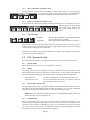
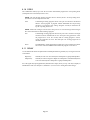
UX8800
DIGITAL SIGNAL PROCESSOR / CROSSOVER
OWNER’S MANUAL
Page is loading ...

1 IMPORTANT SAFETY INSTRUCTIONS - READ THIS FIRST
Read and heed all warnings and safety instructions in this Manual before using the product. Failure to
follow all precautions can result in equipment damage, personal injury, or death.
1.1 Important Safety Instructions for Electronic Products
The lightning flash with arrowhead symbol within an equilateral triangle is intended to alert the user to the
presence of uninsulated "dangerous voltage" within the product's enclosure that may be of sufficient
magnitude to constitute a risk of electric shock to persons.
The exclamation point within an equilateral triangle is intended to alert the user of the presence of important
operating and maintenance (servicing) instructions in the literature accompanying the appliance.
1. Read these instructions.
2. Keep these instructions.
3. Heed all warnings.
4. Follow all instructions.
5. Do not use this apparatus near water.
6. Clean only with dry cloth.
7. Do not block any ventilation openings. Install in accordance with the manufacturer's
instructions.
8. Do not install near any heat sources such as radiators, heat registers, stoves, or other apparatus
(including amplifiers) that produce heat.
9. Do not defeat the safety purpose of the polarized or grounding-type plug. A polarized plug has
two blades with one wider than the other. A grounding type plug has two blades and a third
grounding prong. The wide blade or the third prong is provided for your safety. If the provided
plug does not fit into your outlet, consult an electrician for replacement of the obsolete outlet.
10. The power plug at the wall must remain accessible to be able to disconnect power from the
apparatus.
11. Protect the power cord from being walked on or pinched particularly at plugs, convenience
receptacles, and the point where they exit from the apparatus.
12. Only use attachments/accessories specified by the manufacturer.
13. Use only with the cart, stand, tripod, bracket, or table specified by the manufacturer, or sold
with the apparatus. When a cart is used, use caution when moving the cart/apparatus
combination to avoid injury from tip-over.
14. Unplug this apparatus during lightning storms or when unused for long periods of time.
15. Refer all servicing to qualified service personnel. Servicing is required when the apparatus has
been damaged in any way, such as power-supply cord or plug is damaged, liquid has been
spilled or objects have fallen into the apparatus, the apparatus has been exposed to rain or
moisture, does not operate normally, or has been dropped.
16. This apparatus shall not be exposed to dripping or splashing, and no object filled with liquid,
such as vases, shall be placed on the apparatus.
17. This apparatus has been designed with Class-I construction and must be connected to a mains
socket outlet with a protective earthing connection (the third grounding prong).
18. This apparatus does not exceed the Class A/Class B (whichever is applicable) limits for radio
noise emissions from digital apparatus as set out in the radio interference regulations of the
Canadian Department of Communications.
ATTENTION: Le présent appareil numérique n'émet pas de bruits radioélectriques dépassant las
limites applicables aux appareils numériques de class A/de class B (selon le cas) prescrites
dans le règlement sur le brouillage radioélectrique édicté par les ministere des communications
du Canada.
Page iii

19. If the loudspeaker is exposed to changes in temperature and humidity, internal condensation
may develop. If powered up with such condensation, electronic failure could result. When
exposed to environmental changes, allow the loudspeaker at least 30 minutes to acclimate to a
new temperature before connecting to the ac mains and operating.
20. EAW loudspeakers can produce sound levels capable of causing permanent hearing damage
from prolonged exposure. The higher the sound level, the less exposure needed to cause such
damage. Avoid prolonged exposure to the high sound levels from the loudspeaker.
DANGER: There is danger of explosion if battery is incorrectly replaced. Replace only with
the same or equivalent type. This applies to any loudspeakers with a battery.
WARNING: TO REDUCE THE RISK OF FIRE OR ELECTRIC SHOCK, DO NOT
EXPOSE THIS APPLIANCE TO RAIN OR MOISTURE. DO NOT EXPOSE THE
APPARATUS TO DRIPPING OR SPLASHING AND DO NOT PLACE OBJECTS FILLED
WITH LIQUIDS, SUCH AS DRINKS, ON THE APPARATUS.
1 CONSIGNES DE SÉCURITÉ - À LIRE EN PREMIER
Lisez et respectez toutes les consignes de sécurité de ce manuel avat d'utiliser le produit. Le non-respect de
ces consignes de sécurité peut entraîner des dommages matériels ou des accidents aux personnes qui
peuvent être fatals.
1.1 Consignes de Sécurité Importantes Relatives aux Produits
Électronique
Le symbole del'éclair dans le triangle équilatéral prévient l'utilisateur de la présence d'une "tension
électrique dangereuse" dans le produit constituant un risque d'électrocution.
Le point d'exclamation dans le triangle équilatéral prévient l'utilisateur de la résence d'instructions
importantes relatives à l'utilisation et à la maintenance du produit dans le manuel fourni avec le produit.
1. Lisez ces instructions.
2. Conservez ces instructions.
3. Respectez toutes les mises en garde.
4. Suivez toutes les intructions.
5. Ne pas utiliser cet appareil près d'une source liquide.
6. Nettoyer uniquement avec un tissu sec.
7. Ne pas obstruer les ouïes de ventilation. Installer selon les instructions du fabriquant.
8. Ne pas installer près d'une source de chaleur cmme des radiateurs, convecteurs, poêles, ou près
de tout appareil (ce qui comprend les amplificateurs de puissance) produisant de la chaleur.
9. Ne pas modifier la sécurité offerte par les fiches secteur polarisées ou avec mise à la terre. Les
fiches polaisées sont équipées de deux lames, dont une plus large que l'autre. Les fiches avec
mise à la terre disposent d'un troisième plot. La mise à la terre garantit la sécurité des
utilisateurs. Si la fiche fournie ne correspond pas au format de vos prises sectur, consultez un
électricien qui pourra les remplacer.
10. La fiche secteur dans la prise murale doit rester accessible pour permettre la déconnexion de
l'appareil du secteur.
11. Protéger le cordon secteur de toute dégradation de sorte que les personnes e puissent pas
marcher dessus. Veiller à ne pas pincer le cordon secteur, de sa sortie de l'appareil, jusqu'à la
connexion dans la prise murale ou autre.
12. Utiliser uniquement les fixations/accessoires spécifiés par le fabriquant.
13. Utiliser uniquemen le chariot, pied, tripode, fixation, ou la table spécifiés par le fabriquant, ou
vendus avec l'appareil. Lors de l'utilisation d'un chariot, vérifier la stabilité de l'ensemble
chariot/équipement pour éviter toute chute et tout accident.
Page iv
Page is loading ...
Page is loading ...
Page is loading ...
Page is loading ...
Page is loading ...

1.2 EC Declaration of Conformity
Eastern Acoustic Works, as the manufacturer, hereby certifies that, in its delivered version,
Product Model: UX8800
Product Description: Audio digital signal processor
complies with the provisions of these directives and standards:
European Council Directive on Low Voltage, 73/23/EEC
European Council Directive on Electromagnetic Compatibility 89/336/EEC and 93/68/EEC
EN 60065:2002 Audio, video, and similar electronic apparatus - safety requirements
EN 55103-1:1997 Electromagnetic compatibility. Product family standard for audio, video,
audio-visual, and entertainment lighting control apparatus for professional use - Emission
EN 55103-2:1997 Electromagnetic compatibility. Product family standard for audio, video,
audio-visual, and entertainment lighting control apparatus for professional use - Immunity
The Technical Report/File is maintained at:
LOUD Technologies Inc. Worldwide Headquarters
16220 Wood-Red Road NE
Woodinville, WA98072 USA
Tel: +1 425 892 6500
Tel: 866 858 5832
Fax: +1 425 487 4337
e-mail: info@eaw.com
Authorized Representative:
Kevin Cyrus
Director of Compliance
LOUD Technologies Inc.
Issued: April 2007
1.3 FCC Information to the User
This equipment has been tested and found to comply with the limits for a Class Adigital device, pursuant to
part 15 of the FCC Rules. These limits are designed to provide reasonable protection against harmful
interference when the equipment is operated in a commercial environment. This equipment generates,
uses, and can radiate radio frequency energy and, if not installed and used in accordance with the
instruction manual, may cause harmful interference to radio communications. Operation of this equipment
in a residential area is likely to cause harmful interference in which case the user will be required to correct
the interference at his own expense.
Page x

CONTENTS
1 IMPORTANT SAFETY INSTRUCTIONS - READ THIS FIRST . . . . . . . . . . . . . . . . . . . . . . . . . . . . . . . . . . .iii
1.1 Important Safety Instructions for Electronic Products . . . . . . . . . . . . . . . . . . . . . . . . . . . . . . . . . . . . . . . . . . . .iii
1 CONSIGNES DE SÉCURITÉ - À LIRE EN PREMIER . . . . . . . . . . . . . . . . . . . . . . . . . . . . . . . . . . . . . . . . . .iv
1.1 Consignes de Sécurité Importantes Relatives aux Produits Électronique . . . . . . . . . . . . . . . . . . . . . . . . . . . . .iv
1 PRECAUZIONI DI SICUREZZA - DA LEGGERE PER PRIMO . . . . . . . . . . . . . . . . . . . . . . . . . . . . . . . . . . .v
1.1 Importanti Norme di Sicurezza per L'uso di Elettronico Prodotti . . . . . . . . . . . . . . . . . . . . . . . . . . . . . . . . . . . .v
1 PRECAUCIONES DE SEURIDAD - LEA ESTO PRIMERO . . . . . . . . . . . . . . . . . . . . . . . . . . . . . . . . . . . . . .vii
1.1 Aviso Importante de Seguridad para Electrónico Productos . . . . . . . . . . . . . . . . . . . . . . . . . . . . . . . . . . . . . . . .vii
1 SICHERHEITSHINWEISE - ZUERST LESEN . . . . . . . . . . . . . . . . . . . . . . . . . . . . . . . . . . . . . . . . . . . . . . . . .viii
1.1 Wichtige Sicherheitsanweisungen für Elektronische Produkte . . . . . . . . . . . . . . . . . . . . . . . . . . . . . . . . . . . . . .viii
1.2 EC Declaration of Conformity . . . . . . . . . . . . . . . . . . . . . . . . . . . . . . . . . . . . . . . . . . . . . . . . . . . . . . . . . . . . . . .x
1.3 FCC Information to the User . . . . . . . . . . . . . . . . . . . . . . . . . . . . . . . . . . . . . . . . . . . . . . . . . . . . . . . . . . . . . . . .x
CONTENTS . . . . . . . . . . . . . . . . . . . . . . . . . . . . . . . . . . . . . . . . . . . . . . . . . . . . . . . . . . . . . . . . . . . . . . . . . . . . .1
2 UNPACKING . . . . . . . . . . . . . . . . . . . . . . . . . . . . . . . . . . . . . . . . . . . . . . . . . . . . . . . . . . . . . . . . . . . . . . . . . . . .2
2.1 Contents . . . . . . . . . . . . . . . . . . . . . . . . . . . . . . . . . . . . . . . . . . . . . . . . . . . . . . . . . . . . . . . . . . . . . . . . . . . . . . . .2
2.2 Shipping Damage . . . . . . . . . . . . . . . . . . . . . . . . . . . . . . . . . . . . . . . . . . . . . . . . . . . . . . . . . . . . . . . . . . . . . . . . .2
2.3 Returning a Processor to EAW . . . . . . . . . . . . . . . . . . . . . . . . . . . . . . . . . . . . . . . . . . . . . . . . . . . . . . . . . . . . . . .2
3 INTRODUCTION . . . . . . . . . . . . . . . . . . . . . . . . . . . . . . . . . . . . . . . . . . . . . . . . . . . . . . . . . . . . . . . . . . . . . . . .3
3.1 UX8800 Description . . . . . . . . . . . . . . . . . . . . . . . . . . . . . . . . . . . . . . . . . . . . . . . . . . . . . . . . . . . . . . . . . . . . . . .3
3.2 Features and Benefits . . . . . . . . . . . . . . . . . . . . . . . . . . . . . . . . . . . . . . . . . . . . . . . . . . . . . . . . . . . . . . . . . . . . . .3
3.3 Networking Capabilities . . . . . . . . . . . . . . . . . . . . . . . . . . . . . . . . . . . . . . . . . . . . . . . . . . . . . . . . . . . . . . . . . . . .3
3.4 Front Panel . . . . . . . . . . . . . . . . . . . . . . . . . . . . . . . . . . . . . . . . . . . . . . . . . . . . . . . . . . . . . . . . . . . . . . . . . . . . .4
3.5 Rear Panel . . . . . . . . . . . . . . . . . . . . . . . . . . . . . . . . . . . . . . . . . . . . . . . . . . . . . . . . . . . . . . . . . . . . . . . . . . . . . . .4
4 UX8800 INSTALLATION . . . . . . . . . . . . . . . . . . . . . . . . . . . . . . . . . . . . . . . . . . . . . . . . . . . . . . . . . . . . . . . . . .5
4.1 Physical Installation . . . . . . . . . . . . . . . . . . . . . . . . . . . . . . . . . . . . . . . . . . . . . . . . . . . . . . . . . . . . . . . . . . . . . . .5
4.2 AC Mains Connections . . . . . . . . . . . . . . . . . . . . . . . . . . . . . . . . . . . . . . . . . . . . . . . . . . . . . . . . . . . . . . . . . . . .5
4.3 Audio Connections . . . . . . . . . . . . . . . . . . . . . . . . . . . . . . . . . . . . . . . . . . . . . . . . . . . . . . . . . . . . . . . . . . . . . . . .6
4.4 Network Connections . . . . . . . . . . . . . . . . . . . . . . . . . . . . . . . . . . . . . . . . . . . . . . . . . . . . . . . . . . . . . . . . . . . . . .6
5 OPERATION - INITIAL SETUP . . . . . . . . . . . . . . . . . . . . . . . . . . . . . . . . . . . . . . . . . . . . . . . . . . . . . . . . . . . . .9
5.1 Power On /Off . . . . . . . . . . . . . . . . . . . . . . . . . . . . . . . . . . . . . . . . . . . . . . . . . . . . . . . . . . . . . . . . . . . . . . . . . . .9
5.2 Front Panel Controls . . . . . . . . . . . . . . . . . . . . . . . . . . . . . . . . . . . . . . . . . . . . . . . . . . . . . . . . . . . . . . . . . . . . . . .9
5.3 UTIL (System Set-Up) . . . . . . . . . . . . . . . . . . . . . . . . . . . . . . . . . . . . . . . . . . . . . . . . . . . . . . . . . . . . . . . . . . . .10
6 OPERATION - SYSTEM PROCESSOR MODE . . . . . . . . . . . . . . . . . . . . . . . . . . . . . . . . . . . . . . . . . . . . . . . .12
6.1 Introduction . . . . . . . . . . . . . . . . . . . . . . . . . . . . . . . . . . . . . . . . . . . . . . . . . . . . . . . . . . . . . . . . . . . . . . . . . . . . .12
6.2 Select System Processor Mode . . . . . . . . . . . . . . . . . . . . . . . . . . . . . . . . . . . . . . . . . . . . . . . . . . . . . . . . . . . . . .12
6.3 Signal Routing . . . . . . . . . . . . . . . . . . . . . . . . . . . . . . . . . . . . . . . . . . . . . . . . . . . . . . . . . . . . . . . . . . . . . . . . . . .12
6.4 CH (Input Channels A to D) . . . . . . . . . . . . . . . . . . . . . . . . . . . . . . . . . . . . . . . . . . . . . . . . . . . . . . . . . . . . . . . . .12
6.5 CH (Output Channels 1 to 8) . . . . . . . . . . . . . . . . . . . . . . . . . . . . . . . . . . . . . . . . . . . . . . . . . . . . . . . . . . . . . . . .12
6.6 LEVEL . . . . . . . . . . . . . . . . . . . . . . . . . . . . . . . . . . . . . . . . . . . . . . . . . . . . . . . . . . . . . . . . . . . . . . . . . . . . . . . . .13
6.7 X-OVER (Output Channels 1 to 8) . . . . . . . . . . . . . . . . . . . . . . . . . . . . . . . . . . . . . . . . . . . . . . . . . . . . . . . . . . .13
6.8 LIM (Output Channels 1 to 8) . . . . . . . . . . . . . . . . . . . . . . . . . . . . . . . . . . . . . . . . . . . . . . . . . . . . . . . . . . . . . . .13
6.9 EQ . . . . . . . . . . . . . . . . . . . . . . . . . . . . . . . . . . . . . . . . . . . . . . . . . . . . . . . . . . . . . . . . . . . . . . . . . . . . . . . . . . . . .13
6.10 PROG . . . . . . . . . . . . . . . . . . . . . . . . . . . . . . . . . . . . . . . . . . . . . . . . . . . . . . . . . . . . . . . . . . . . . . . . . . . . . . . . . .14
6.11 DELAY . . . . . . . . . . . . . . . . . . . . . . . . . . . . . . . . . . . . . . . . . . . . . . . . . . . . . . . . . . . . . . . . . . . . . . . . . . . . . . . . .14
7 OPERATION - LOUDSPEAKER PROCESSOR MODE . . . . . . . . . . . . . . . . . . . . . . . . . . . . . . . . . . . . . . . . . .15
7.1 Introduction . . . . . . . . . . . . . . . . . . . . . . . . . . . . . . . . . . . . . . . . . . . . . . . . . . . . . . . . . . . . . . . . . . . . . . . . . . . . .15
7.2 Select Loudspeaker Processor Mode . . . . . . . . . . . . . . . . . . . . . . . . . . . . . . . . . . . . . . . . . . . . . . . . . . . . . . . . .15
7.3 Signal Routing . . . . . . . . . . . . . . . . . . . . . . . . . . . . . . . . . . . . . . . . . . . . . . . . . . . . . . . . . . . . . . . . . . . . . . . . . . .16
7.4 CH (Input Channels A to D) . . . . . . . . . . . . . . . . . . . . . . . . . . . . . . . . . . . . . . . . . . . . . . . . . . . . . . . . . . . . . . . . .16
7.5 CH (Output Channels 1 to 8) . . . . . . . . . . . . . . . . . . . . . . . . . . . . . . . . . . . . . . . . . . . . . . . . . . . . . . . . . . . . . . . .17
7.6 LEVEL (Input Channels A to D) . . . . . . . . . . . . . . . . . . . . . . . . . . . . . . . . . . . . . . . . . . . . . . . . . . . . . . . . . . . . .18
7.7 X-OVER (Input Channels A to D) . . . . . . . . . . . . . . . . . . . . . . . . . . . . . . . . . . . . . . . . . . . . . . . . . . . . . . . . . . . .18
7.8 EQ (Input Channels A to D) . . . . . . . . . . . . . . . . . . . . . . . . . . . . . . . . . . . . . . . . . . . . . . . . . . . . . . . . . . . . . . . . .19
7.9 PROG . . . . . . . . . . . . . . . . . . . . . . . . . . . . . . . . . . . . . . . . . . . . . . . . . . . . . . . . . . . . . . . . . . . . . . . . . . . . . . . . . .19
7.10 DELAY (Input Channels A to D) . . . . . . . . . . . . . . . . . . . . . . . . . . . . . . . . . . . . . . . . . . . . . . . . . . . . . . . . . . . . .19
8 LED INDICATORS . . . . . . . . . . . . . . . . . . . . . . . . . . . . . . . . . . . . . . . . . . . . . . . . . . . . . . . . . . . . . . . . . . . . . . .20
8.1 Ethernet . . . . . . . . . . . . . . . . . . . . . . . . . . . . . . . . . . . . . . . . . . . . . . . . . . . . . . . . . . . . . . . . . . . . . . . . . . . . . . . . .20
8.2 U-Net Indicators . . . . . . . . . . . . . . . . . . . . . . . . . . . . . . . . . . . . . . . . . . . . . . . . . . . . . . . . . . . . . . . . . . . . . . . . . .20
8.3 Input meters . . . . . . . . . . . . . . . . . . . . . . . . . . . . . . . . . . . . . . . . . . . . . . . . . . . . . . . . . . . . . . . . . . . . . . . . . . . . .20
8.4 Output Meters . . . . . . . . . . . . . . . . . . . . . . . . . . . . . . . . . . . . . . . . . . . . . . . . . . . . . . . . . . . . . . . . . . . . . . . . . . . .20
9 EAWPILOT . . . . . . . . . . . . . . . . . . . . . . . . . . . . . . . . . . . . . . . . . . . . . . . . . . . . . . . . . . . . . . . . . . . . . . . . . . . . .21
9.1 Extra Capabilities . . . . . . . . . . . . . . . . . . . . . . . . . . . . . . . . . . . . . . . . . . . . . . . . . . . . . . . . . . . . . . . . . . . . . . . . .21
10 MAINTENANCE AND SERVICE . . . . . . . . . . . . . . . . . . . . . . . . . . . . . . . . . . . . . . . . . . . . . . . . . . . . . . . . . . .22
10.1 Maintenance . . . . . . . . . . . . . . . . . . . . . . . . . . . . . . . . . . . . . . . . . . . . . . . . . . . . . . . . . . . . . . . . . . . . . . . . . . . . .22
10.2 Service . . . . . . . . . . . . . . . . . . . . . . . . . . . . . . . . . . . . . . . . . . . . . . . . . . . . . . . . . . . . . . . . . . . . . . . . . . . . . . . . .22
10.3 Return and Repair Issues . . . . . . . . . . . . . . . . . . . . . . . . . . . . . . . . . . . . . . . . . . . . . . . . . . . . . . . . . . . . . . . . . . .22
10.4 How To Contact EAW . . . . . . . . . . . . . . . . . . . . . . . . . . . . . . . . . . . . . . . . . . . . . . . . . . . . . . . . . . . . . . . . . . . . .22
11 TROUBLESHOOTING . . . . . . . . . . . . . . . . . . . . . . . . . . . . . . . . . . . . . . . . . . . . . . . . . . . . . . . . . . . . . . . . . . . .23
12 BLOCK DIAGRAMS . . . . . . . . . . . . . . . . . . . . . . . . . . . . . . . . . . . . . . . . . . . . . . . . . . . . . . . . . . . . . . . . . . . . .24
12.1 System Processor Mode . . . . . . . . . . . . . . . . . . . . . . . . . . . . . . . . . . . . . . . . . . . . . . . . . . . . . . . . . . . . . . . . . . . .24
12.2 Loudspeaker Processor Mode . . . . . . . . . . . . . . . . . . . . . . . . . . . . . . . . . . . . . . . . . . . . . . . . . . . . . . . . . . . . . . .25
APPENDIX . . . . . . . . . . . . . . . . . . . . . . . . . . . . . . . . . . . . . . . . . . . . . . . . . . . . . . . . . . . . . . . . . . . . . . . . . . . . . . . . . . . . . . .26
A Greybox Information . . . . . . . . . . . . . . . . . . . . . . . . . . . . . . . . . . . . . . . . . . . . . . . . . . . . . . . . . . . . . . . . . . . . . .26
B System Processor Mode Processing . . . . . . . . . . . . . . . . . . . . . . . . . . . . . . . . . . . . . . . . . . . . . . . . . . . . . . . . . . .26
Page 1

2 UNPACKING
2.1 Contents
1 UX8800 Digital Processor
1 set Internal support packaging
1 IEC Power cable 6 ft / 2 m with Nema 15-3 ac mains plug for 115V / 120 V
1 IEC Power cable 6 ft / 2 m with Schuko type ac mains plug for 220 V / 240 V
1 Ethernet crossover cable 7 ft / 2.1 m
1 4 A, slow-blow replacement fuse (in rear panel fuse drawer)
1 UX8800 Owner’s Manual (this document)
1 CD-ROM with EAWPilot control software and a trial version of Smaart v.6
1 Product registration instructions
2.2 Shipping Damage
If you find the processor is damaged after unpacking, save the packing materials for the carrier’s
inspection, notify the carrier immediately, and file a shipping damage claim. Although EAW will help in
any way possible, it is always the responsibility of the receiving party to file any shipping damage claim.
The carrier will help prepare and file this claim.
2.3 Returning a Processor to EAW
If the processor must be returned, contact EAW for a Return Authorization. Use the original shipping
carton and packing materials. If the shipping carton is damaged, contact EAWfor a new carton at a nominal
charge. EAW will not be responsible for damage caused by inadequate packing.
Page 2

Page 3
3 INTRODUCTION
Congratulations on purchasing the innovative UX8800 digital signal processor (DSP) from Eastern
Acoustic Works. While designed with the fundamental principles of close-coupled processing used since
the first MX Series Processors in the 1980s, the UX8800 uses EAW’s latest advances in digital technology
to provide optimum signal processing and management of EAW loudspeaker systems.
3.1 UX8800 Description
The UX8800 is a 4-input, 8-output digital signal processor that operates in either of two modes:
System Processor: The UX8800 functions as a user-controlled, digital signal processor for
loudspeakers or for other applications requiring similar processing functions.
Loudspeaker Processor: The UX8800 functions to provide sophisticated, EAW-engineered
digital processing for specific portable and installed EAW loudspeakers.
In System Processor mode, the UX8800 provides a complete suite of state-of-the art, digital signal
processing tools, including 10 EQ filters and signal delay (up to 1200 ms) for each input and output,as well
as gain, polarity, limiting, and crossover filters.
In Loudspeaker Processor mode, one can create up to four different EAW loudspeaker processors for
specific EAWloudspeaker products or loudspeaker arrays. These are referred to as “Greyboxes.” This term
comes from certain parameters not being user adjustable (“black-boxed”), certain parameters being user
adjustable (“white-boxed,” as it were), with the combination of black/white being grey. Greybox settings
consist of preset, EAW-engineered processing parameters for the crossovers, equalization, limiting, and
other settings as an integral part of that loudspeaker’s design and operation. These settings include EAW’s
digital processing invention called Gunness Focusing™. In addition, preset limiting parameters are
designed to maximize sonic performance during active limiting while providing robust driver protection.
These preset parameters are locked down to prevent inadvertent or purposeful modifications. However, the
user retains control of gain, input EQ, signal delay, and polarity for each Greybox loudspeaker.
The simplicity of the Loudspeaker Processor mode makes the UX8800 practical for entry level users and
fast to operate for professional users. This function provides for a high level of system consistency while
retaining all necessary user alignment controls.
3.2 Features and Benefits
• Multiple Mode operation – Allows use as standard system processor or as dedicated
loudspeaker processor.
• “Greybox” operation – Complete processing presets for EAW loudspeakers provides ease of
setup, consistency, and interoperability between EAW products and systems.
• Comprehensive and intuitive front panel control – Access to operational parameters making
computer control unnecessary for simple and quick adjustments.
• U-Net – EAW-designed signal and control networking between U-Net enabled products.
• Digital inputs (U-Net and AES/EBU) – Reduces the total number of A/D & D/A stages.
• EAWPilot software – Comprehensive software control of all hardware parameters.
• Gunness Focusing capable – Implements Gunness Focusing for specific EAW loudspeaker
systems using the “Greybox” mode.
• All filter parameters are compatible with EAW’s measurement and modeling software - Allows
the creation of advanced array processing.
• Advanced Greybox Limiting - Provides more robust driver protection and better sonic
performance based on specific EAW driver and loudspeaker performance characteristics.
3.3 Networking Capabilities
Standard Ethernet protocol and cabling is used to communicate with and control the processor. Both audio
and control signals can be transmitted between additional processors using the built-in U-Net network and
standard CAT-5 cabling with RJ-45 connectors. Up to 254 UX8800 processors can be linked using U-Net
so that all processors can be controlled by EAWPilot. The wiring configuration for U-Net can be a daisy-
chain (serial), a star, or a circular loop.

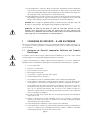
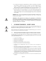
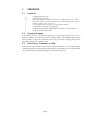
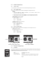
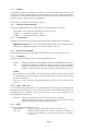
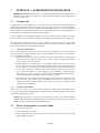
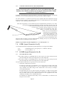
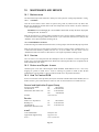
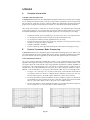
3.4 Front Panel
1. Ethernet For connection to a PC or to an Ethernet hub or switch; LEDs indicate connection status.
2. U-Net Indicators LEDs indicate U-Net status.
3. Input Channels A to D Selects the input channel for display of or editing its parameters selected by a Function button.
4. Input Channel Meters Provides input metering after the ADC (analog to digital converter).
5. Input Channel Mutes Mutes the output signal of the corresponding input channel.
6. LCD Display Displays parameters for function selected by the function buttons.
7. Encoder Knob Joystick control for navigating menus and changing parameter settings.
8. Function Buttons Selects the function to be displayed or edited in the LCD display.
9. Output Channels 1 to 8
Selects the output channel for display of or editing its parameters selected by a Function button.
10. Output Channel Meters
Provides output metering before the DAC (digital to analog converter).
11. Output Channel Mutes
Mutes the signal and U-Net outputs of the corresponding output channel.
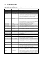
3.5 Rear Panel
12. IEC Receptacle ac mains input, 100 V to 240 V, 50 Hz to 60 Hz.
13. ac mains fuse 4 A, slow-blow (main and spare in IEC Receptacle drawer).
14. Power ac mains on and off.
15. Outputs 1 to 8 XLR connectors for audio outputs (analog).
16. Inputs A to D XLR connectors for audio inputs (analog for A to D or AES/EBU for A & C only).
17. U-Net 1 and 2 Network ports for audio input, audio output, and control connections to additional
UX8800s and other U-Net enabled products.
Page 4
UX
UX
880
80
0
Speaker / System Processor
Speaker / System Processor
INPUT CHANNELS
INPUT CHANNELS
OUTPUT CHANNELS
OUTPUT CHANNELS
ETHERNET
ETHERNET
Clip
Clip
Lim
Lim
-12
-12
Sig
Sig
Clip
Clip
Lim
-12
-12
Sig
Sig
Clip
Clip
Lim
Lim
-12
-12
Sig
Sig
Clip
Clip
Lim
Lim
-12
-12
Sig
Sig
Clip
Clip
Lim
Lim
-12
-12
Sig
Sig
Clip
Clip
Lim
Lim
-12
-12
Sig
Sig
Clip
Clip
Lim
Lim
-12
-12
Sig
Sig
Clip
Clip
Lim
Lim
-12
-12
Sig
Sig
Clip
Clip
-6
-6
-12
-12
Sig
Sig
Clip
Clip
-6
-6
-12
-12
Sig
Sig
Clip
Clip
-6
-6
-12
-12
Sig
Sig
Clip
Clip
-6
-6
-12
-12
Sig
Sig
U-NET
U-NET
1
2
LEVELCH
X-OVER LIM
EQ PROG
DELAY UTIL
MUTE MUTE MUTE MUTE MUTE MUTE MUTE MUTE MUTE MUTE MUTE MUTE
A
B
CD
12345678
Crossover
Limiter
EQ
SELECT
1
2
3
4
5
6
7
8
9
10
11
INPUTSOUTPUTS
87654321
2
1
U-NET
POWER
~100-240 VAC
50-60Hz 75W
ANALOG
PUSH
ANALOG/AES
ANALOG/AESANALOG
PUSH
PUSH
PUSH
D C B A
12
13
14
15
17
16

4 UX8800 INSTALLATION
4.1 Physical Installation
CAUTION: The UX8800’s operating temperature range is 32 F to 104 F degrees / 0 C to 40
C degrees. The UX8800 may not function properly in temperatures below this range and may
be damaged in temperatures above this range.
4.1.1 MOUNTING
The UX8800 is designed to mount in a standard, 19 in equipment rack occupying one EIArack space (1.75
in). When rack mounting, use screws with mating plastic washers to help protect the finish of the UX8800.
The UX8800 weighs approximately 10 lb / 4.5 kg.
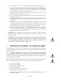
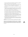
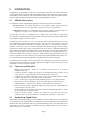
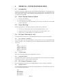
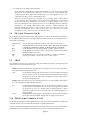
4.1.2 VENTILATION
An integral fan is used to properly ventilate the
UX8800. The fan is located to the rear of the left
side of the chassis. The air intake grilles are located
on the right side and on top of the chassis. Maintain
clearances around the left and right sides of the
chassis as shown in the drawing.
It is recommended to leave one empty rack space
above the UX8800 to provide 1.75 in / 45 mm
clearance above the top air intake holes for
additional ventilation.
4.2 AC Mains Connections
4.2.1 AC MAINS VOLTAGE
The UX8800 has a universal, auto-ranging power supply that operates from 100 Vto 240 V, 50 Hz to 60 Hz.
The UX8800 is compatible with these nominal ac mains:
100 V, 110 V, 115 V, 120 V, 127 V, 220 V, 230 V, and 240 V at 50 Hz to 60 Hz.
CAUTION: To maintain compliance ratings, keep the ac mains voltage between
100 V to 240 V.
4.2.2 IEC POWER CORD RECEPTACLE
An IEC-320 ac mains inlet on the rear panel accepts the detachable power cords supplied with the unit. Use
the power cord appropriate for these nominal ac mains supply voltages.
120 V ac mains: use the power cord with the NEMA 5-15 plug, EAW part # 640-01-00
220 V ac mains: use the power cord with the Schuko plug, EAW part # 640-02-02
CAUTION: It is the user’s responsibility to provide a proper ac mains plug for any
ac mains outlet configuration that differs from those supplied with the product.
4.2.3 GROUNDING
The chassis of this product is grounded through the grounding conductor of the power cord. To avoid
electric shock, plug the power cord into a properly wired and grounded receptacle before making any
connections to or operating the product.
DANGER: This equipment must be operated with the power cord grounding conductor
connected to a properly grounded ac outlet. Do not disconnect, “lift,” or otherwise remove this
ground connection. Without this connection, accessible parts, including knobs and controls
that may appear to be insulated, can render an electric shock that can cause injury or death to
operating personnel.
Page 5
MAINTAIN 1 in / 25 mm
CLEARANCE AROUND
SIDE AIR INTAKE GRILLES
RECOMMENDED:
MAINTAIN 1-3/4 in / 45 mm CLEARANCE
ABOVE TOP AIR INTAKE GRILLES
MAINTAIN 2 in / 50 mm
CLEARANCE AROUND
FAN EXHAUST GRILLE
AIR FLOW
VENTILATION CLEARANCES
POWER
~100-240 VAC
50-60Hz 75W

4.3 Audio Connections
4.3.1 SIGNAL CABLE
Use a good quality, 2-conductor shielded cable for all audio input and output connections.
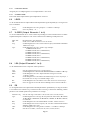
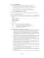
4.3.2 INPUT CONNECTIONS
The four, female, XLR-type connectors labeled Athrough D are audio input connectors.
NOTES:
1. Select the signal type, analog or AES/EBU, in the hardware Utilities menu or
EAWPilot/UX8800 settings window.
2. XLR connector B is inactive when AES/EBU is selected for XLR connector A & B.
3. XLR connector D is inactive when AES/EBU is selected for XLR connector C & D.
Analog Pin-Out: XLR A to XLR D
Electronically balanced, line level
Pin 1: Shield
Pin 2: + (plus or high)
Pin 3: - (minus or low)
AES/EBU Pin-Out: XLR A and XLR C
Transformer isolated, balanced.
Pin 1: Signal ground (shield)
Pin 2: Channel 1
Pin 3: Channel 2
4.3.3 OUTPUT CONNECTIONS
The eight, male, XLR-type connectors labeled 1 through 8 are the audio output connectors.
Analog: XLR 1 to XLR 8
Electronically balanced, line level.
Pin 1: shield
Pin 2: + (plus or high)
Pin 3: - (minus or low)
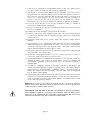
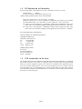
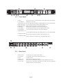
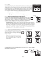
4.4 Network Connections
4.4.1 ETHERNET
The UX8800 communicates with a computer through its built-in, front panel, Ethernet port. This port is
configured as a standard NIC (network interface card). The UX8800 can be connected to an Ethernet
network using hub, switch, router, or wireless connections.
Cable: 8 conductor CAT-5 or better
Mating Connector: RJ-45 male
Wiring Configuration: Standard for connection to a network hub, switch, or router
Crossover type for direct connection to a computer’s NIC
Page 6
ETHERNET
ETHERNET
U-NET
1
2
21
ANALOG
PUSH
ANALOG/AES
ANALOG/AES
PUSH
PUSH
D C
A
ANALOG
PUSH
B
1 Shield
2+3- 2+ 3-
2 Signal
1 Signal Earth
(cable shield)
3 Signal
1 Shield
OUTPUT (analog) INPUT (analog) INPUT (digital - AES/EBU)

4.4.2 U-NET
The UX8800 can be networked with additional UX8800s and other U-Net enabled products
through its built-in U-Net ports. The rear panel U-Net 1 and U-Net 2 ports are bi-directional
communication ports used to communicate audio and/or control signals. Either or both ports may
be used to connect to other U-Net enabled products. When U-Net ports are connected, control
signals are automatically sent and received. Audio signals must be assigned to be sent and received
over U-Net channels using the CH function for the Input Channels and/or Output Channels.
Cable: 8 conductor CAT-5 cable or better
Mating Connector: RJ-45 male
Wiring Configuration: Standard or crossover (supplied)
NOTE: The U-Net ports auto-sense the cable wiring configuration.
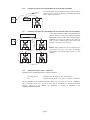
4.4.3 CONNECTING ONE PROCESSOR TO ONE COMPUTER
Use the processor’s front panel Ethernet port and the supplied Ethernet crossover cable to
connect directly to a computer’s 10, 10/100, or 100 Mbps Ethernet port. A user-supplied,
shorter or longer cable may be substituted. The UX8800’s Ethernet port is auto-
negotiating, meaning it will automatically exchange information over a link about speed
and duplex capabilities and negotiate these to the highest common denominator.
CAUTION: An Ethernet crossover cable is required when connecting two Ethernet ports in the
same layer of the OSI model (Open Systems Interconnection Reference Model). A computer’s
Ethernet port, meaning its NIC (network interface card), and the UX8800 are both OSI layer
3 ports. Therefore, an Ethernet crossover cable is REQUIRED when directly connecting the
UX8800 to a computer’s NIC. An Ethernet crossover cable reverses transmit and receive pin
connections between the connectors at each end of the cable.
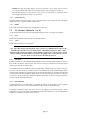
4.4.4 CONNECTING ONE COMPUTER TO MULTIPLE PROCESSORS USING U-NET
Use the front panel Ethernet port on one processor to
connect to a computer as in Section 4.5.1 above. This
processor serves as a bridge to the U-Net network.
Connect other processors and this processor together
using the U-Net ports.
NOTE: Audio signals may also be routed between
processors over the same U-Net cables by assigning
other U-Net inputs and outputs to the input and
output channels.
4.4.5 CONNECTING ONE PROCESSOR TO AN ETHERNET NETWORK
Use the front panel Ethernet port and a standard Ethernet cable to connect to a 10, 10/100, or 100 Mbps
Ethernet hub or switch on the network.
Page 7
PC
EAWP ILOT
UX8800 "A"
U-Net
1
U-Net
2
Ethernet
Ethernet
Hub or Switch
2
1
U-NET
PC
EAWP ILOT
UX8800 "A"
U-Net
1
U-Net
2
Ethernet
CROSSOVER CABLE
(SUPPLIED)
PC
EAWP ILOT
UX8800 "A"
U-Net
1
U-Net
2
U-Net
1
U-Net
2
U-Net
1
U-Net
2
U-Net
1
U-Net
2
UX8800 "C"
UX8800 "B"
UX8800 "D"
EthernetEthernet
Ethernet
Ethernet

4.4.6 CONNECTING MULTIPLE PROCESSORS TO AN ETHERNET NETWORK
Use the front panel Ethernet port and a standard Ethernet cable to
connect each processor to a 10, 10/100, or 100 Mbps Ethernet hub,
switch, or router on a network.
4.4.7 CONNECTING MULTIPLE PROCESSORS TO AN ETHERNET AND U-NET NETWORK
Use the front panel Ethernet port and a standard Ethernet
cable to connect processors to a 10, 10/100, or 100 Mbps
Ethernet hub, switch, or router on the network. Connect
additional processors to the Ethernet hub, switch, or
router or connect additional processors to the system
using the U-Net ports as in Section 4.4.4.
NOTE: Audio signals may also be routed between
processors over the same U-Net cables by assigning
Input Channel and Output Channel signals to U-Net
channels.
4.4.8 SOFTWARE INSTALLATION -- EAWPILOT
EAWPilot requires an IBM compatible PC equipped as follows:
Operating System: Windows Vista, XP, 2000, NT, ME, or Windows 98
I/O: Ethernet network interface card (NIC) 10, 10/100, or 100 Mbps
The latest EAWPilot can be downloaded from the EAW web site: www.eaw.com. Go to the “Downloads”
page or contact the factory and a copy will be sent to you on a CD-ROM. Once installed and with the
computer connected to the UX8800, open EAWPilot by clicking on EAWPilot in the
Start/Programs/EAW/EAWPilot.
Page 8
PC
EAWP ILOT
UX8800 "A"
U-Net
1
U-Net
2
Ethernet
Ethernet
Hub or Switch
To additional
UX8800(s)
PC
EAWP ILOT
UX8800 "A"
U-Net
1
U-Net
2
U-Net
1
U-Net
2
U-Net
1
U-Net
2
U-Net
1
U-Net
2
UX8800 "C"
UX8800 "B"
UX8800 "D"
EthernetEthernet
Ethernet
Ethernet
Ethernet Hub or Switch

5 OPERATION - INITIAL SETUP
WARNING: A digital processor provides a wide range of signal processing parameters. The
results of using incorrect or improper parameters with a loudspeaker can range from poor
sound quality to damage to the loudspeaker. Be sure any settings you make do not cause the
capabilities of the drivers in the loudspeaker system to be exceeded.
5.1 Power On /Off
CAUTION: Before powering on the processor, make all connections to the processor and
ensure there is no audio signal present at the processor’s inputs.
Use the UX8800’s rear panel power switch to turn the ac mains supply to the processor on and off.
Always follow prudent audio system practices and procedures for powering on equipment by powering up
all equipment in the direction of the signal flow order, meaning from the input to the output of the audio
system. Power down the equipment in the reverse of this order.
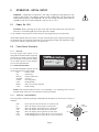
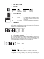
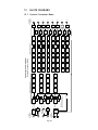
5.2 Front Panel Controls
5.2.1 DISPLAY
The LCD (liquid crystal display) screen,
along with the function buttons and joystick
provides the user interface for operating the
processor from the front panel. The display
can be adjusted for best viewing using the
UTIL / LCD Contrast function.
5.2.2 FUNCTION BUTTONS
Use the function buttons to display and edit
the operating parameters of the UX8800.
CH Channel setup
EQ Channel EQ
DELAY Channel signal delay
X-OVER Crossover
LEVEL Gain and polarity
LIM Output limiting
PROG Store and recall user programs
UTIL Global settings
NOTE: Some function buttons will have no corresponding screen depending on the mode of
operation and the channel selected. This will be indicated in the display.
5.2.3 JOYSTICK - DATA ENCODER
This is the primary control for operating the UX8800 from the front panel. The joystick has seven degrees
of motion.
Push Enters and exits edit mode for the selected menu item.
Up Moves the display cursor up between menu items.
Down Moves the display cursor down between menu items.
Left Moves the display cursor left between menu items.
Right Moves the display cursor right between menu items.
CW Scrolls through parameter values for the selected menu item.
CCW Scrolls through parameter values for the selected menu item.
Page 9
UX
UX
880
80
0
Speaker / System Processor
Speaker / System Processor
LEVELCH
X-OVER LIM
EQ PROG
DELAY UTIL
Crossover
Limiter
EQ
SELECT
PUSH
DOWN
UP
LEFT
RIGHT
ROTATE
COUNTER-
CLOCKWISE
ROTATE
CLOCKWISE

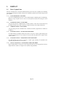
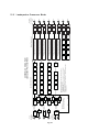
5.2.4 INPUT CHANNELS: BUTTONS A TO D
Pressing an INPUT channel button will illuminate the button and the display screen will display the
selected function’s parameters for this input. This action will also illuminate
the buttons for any output channels to which this input’s audio is routed.
5.2.5 OUTPUT CHANNELS: BUTTONS 1 TO 8
Pressing an OUTPUT button will illuminate the button and the display screen will display the selected
function’s parameters for this output.
This action will not illuminate the
input button routing audio to this
output.
5.2.6 MUTE BUTTONS
Input Mutes: Mutes the output signal of the corresponding Input Channel.
This does not mute the U-Net output.
Output Mutes: Mutes signal to both the output XLR and U-Net output.
Mute settings are not saved with and therefore not recalled from Program files saved in the processor’s
memories. However, the behavior of the mutes may be changed when a program is recalled according to
the Program Load setting made in the UTIL menus.
In contrast, mute settings are saved as part of EAWPilot files (*.ept files) and are uploaded to the processor
as part of the settings stored in those files.
5.3 UTIL (System Set-Up)
The UTIL function menu items are the global parameters for the processor. Set these parameters first.
5.3.1 DEVICE NAME
Enter a unique name for the processor, up to 16 alphanumeric characters.
5.3.2 MODE
Select the operating mode. When changing processor modes all settings will be reset to the factory default
settings for that mode. In order to avoid losing any custom settings, save them using the PROG function
before switching modes. During the mode change, the processor reboots itself and mutes all outputs.
System Processor The processor functions as a standard digital signal processor.
Loudspeaker Processor The processor functions using factory set “Greybox” settings for
particular EAW loudspeaker products.
5.3.3 INPUTS A&B / INPUTS C&D
Select the signal, Analog or AES (=AES/EBU), for Inputs A&B and Inputs C&D. The sample rate for the
AES signal can be 44.1 kHz, 48 kHz, 88.2 kHz, or 96 kHz. The sample-rate converter in the UX8800 will
convert the input sample rates to 48 kHz sample rate required for its internal processing.
NOTE: Input connector B is disabled when digital is selected for Inputs AB and Input connector D is
disabled when digital is selected for Inputs CD.
5.3.4 TEMPERATURE
Enter the ambient temperature. This value is used to calculate the displayed delay distances. These
distances depend on the speed of sound, which depends on the temperature of the air through which the
sound passes. The temperature is adjustable in one degree increments between 32 F degrees and 104 F
degrees or 0 C degrees to 40 C degrees, depending on the Units setting. In Loudspeaker Processor mode,
the temperature is also used to calculate the air loss pre-emphasis.
Page 10
INPUT CHANNELS
INPUT CHANNELS
A
B
CD
OUTPUT CHANNELS
OUTPUT CHANNELS
12345678
INPUTS
Clip
-6
-12
Sig
Sig
Clip
-6
-12
Sig
Sig
Clip
-6
-12
Sig
Sig
Clip
-6
-12
Sig
Sig
MUTE MUTE MUTE MUTE

5.3.5 HUMIDITY
This is only functional in Loudspeaker Processor mode. Enter the relative humidity. This value is used to
calculate the Air Loss Pre-emphasis filters. The air loss depends on the temperature, humidity, and distance
to the listeners. The humidity is adjustable between 10% and 100% in 1% increments. Below 10%, the
absorptive properties of air have not been well quantified.
If in System Processor mode, this setting may be ignored.
5.3.6 PROGRAM LOAD OPERATION
Select the mute options for when a saved program is recalled and loaded into active memory.
Current Mutes The current input and output mute settings are used.
All Mutes All inputs and outputs are muted.
No Mutes All inputs and outputs are unmuted.
5.3.7 LCD CONTRAST
Adjust the LCD contrast value over the range of 0 to 100% for the best display for the viewing angle.
IMPORTANT NOTE: If the contrast is so bad that the display cannot be read, adjust the contrast by
holding the UTIL button and turning the encoder until the display can be read.
5.3.8 UNIT OF MEASUREMENT
Select the unit of measurement used in display of the delay distance and temperature: metric or U.S.
5.3.9 IP ADDRESS
Configure the IP (Internet Protocol) address for the front panel Ethernet port:
Dynamic IPaddress is assigned by a network DHCP (Dynamic Host Configuration Protocol) server.
Static Manually enter an IP address, normally a “private” IP address. The first three number
groups in the IP address must be the same for both the computer and the UX8800. For
example: 192.168.0.N, with N being an integer from 1 to 254, unique to each device.
NOTES:
Private IP addresses are non-routable, meaning addresses that do not work over the Internet. Details
for configuring IP addresses is beyond the scope of this manual, however, this information is readily
available over the Internet.
It may be necessary to change the method EAWPilot uses to query devices and obtain their IP
addresses.
5.3.10 FRONT PANEL LOCK
Use this to lock the front panel functions, except the Mute buttons, from being operated. If you forget the
password, the processor must be reset. This will reset ALL parameters to the factory default settings, erase
all programs stored in Loudspeaker Processor memories, and erase the existing password. See the
Troubleshooting Section for details.
Panel Lock Follow the prompts and enter a Pass Code for locking the front panel.
Follow the prompts and enter the previously entered Pass Code to unlock the front
panel and allow parameter adjustments and other changes.
5.3.11 ABOUT
Select to view information about the processor:
Version Number: Displays the version of the firmware installed in the processor.
Device ID: Displays the unique hardware ID assigned at the factory. EAWPilot uses
this device ID to identify and recognize each particular device to which it
can connect.
Page 11

Page 12
6 OPERATION - SYSTEM PROCESSOR MODE
6.1 Introduction
System Processor mode configures the processor for standard, digital signal processing functions. These
functions consist of Input Channel and Output Channel processing that includes equalization filters, signal
delay, polarity, gain, crossover filters, limiting, and high/low-pass filters. All parameters are user
accessible and user adjustable.
6.2 Select System Processor Mode
1. Select the UTIL function.
2. Scroll down to and select: Mode
3. Select: System Processor. This will reboot the processor and reset all parameters to their default
settings for this mode.
6.3 Signal Routing
In order to pass signal, these tasks must be completed as detailed in the sections listed.
1. Select the type of input signal connected to the XLR input connectors (5.3.3).
2. Assign one or two sources (input connector signals) to each input channel (6.4.1).
3. Assign a source (an input channel) to each output channel (6.5.1).
6.4 CH (Input Channels A to D)
Use the CH function to set the parameters for Input Channels Ato D by selecting the Ato D buttons.
6.4.1 SRC - SOURCE 1 / SOURCE 2
Select either a single source or a sum of two sources. The same source can be selected for multiple Input
Channels. The source choices available depend on the configuration of the Input Channels as set in the
UTIL menu.
None
Analog A / AES A CH 1
Analog B / AES A CH 2
Analog C / AES B CH 1
Analog D / AES B CH 2
U-Net 1 to 32
6.4.2 CHANNEL NAME
Enter a name for the input channel, up to 16 alphanumeric characters.
6.4.3 U-NET OUT ASSIGN
Assign the summed, unprocessed sources to a U-Net output channel. This is useful for daisy-chaining a
single analog or AES source signal to multiple UX8800 units.
6.5 CH (Output Channels 1 to 8)
Use the CH function to set the parameters for Output Channels 1 to 8 by selecting the 1 to 8 buttons.
6.5.1 SOURCE SELECT
Select one of the Input Channels as a source for the Output Channel. The same Input Channel can be the
source for multiple Output Channels.
None
Input Channel A
Input Channel B
Input Channel C
Input Channel D

6.5.2 U-NET OUT ASSIGN
Assign the processed output signal to a U-Net output channel: U-Net 1 to 32
6.5.3 CHANNEL NAME
Enter a name for the output channel, up to 16 alphanumeric characters.
6.6 LEVEL
Use the LEVEL function to set Input Channel and Output Channel gain and polarity by selecting the Ato
D or 1 to 8 buttons.
Level: Scroll through and select the gain up to +/- 15 dB in 0.1 dB steps.
Polarity: Select the polarity: + or -.
6.7 X-OVER (Output Channels 1 to 8)
Use the X-OVER function to set crossover filters for providing an acoustic transition between a multi-
amplified loudspeaker’s subsystems. The crossover filters have the following variable parameters:
HPF / LPF High Pass Filter / Low Pass Filter
Filt: Set the selected HPF or LPF to be active or inactive.
Freq: Scroll through and select the crossover filter frequency from 20 Hz to 20 kHz in
1/24th Octave steps.
Type: Scroll through and select the crossover type and slope:
6 dB Butterworth, Bessel
12 dB Butterworth, Bessel, Linkwitz-Riley
18 dB Butterworth, Bessel
24 dB Butterworth, Bessel, Linkwitz-Riley
30 dB Butterworth, Bessel
36 dB Butterworth, Bessel, Linkwitz-Riley
42 dB Butterworth, Bessel
48 dB Butterworth, Bessel, Linkwitz-Riley
6.8 LIM (Output Channels 1 to 8)
Use the LIM function to set the compressor / limiter parameters:
Lim: Sets the Comp/Lim to In (active) or Out (inactive).
Thrsh: Scroll through and select the limiter threshold from 20 dBu to -10 dBu in 0.1 dB steps.
Ratio: Scroll through and select the compression ratio in integer increments:
1:1 to 20:1, or Inf:1.
Atk: Scroll through and select the limiter attack from 40 µs to 1 ms in 10 µs steps, 1
ms to 40 ms in 1 ms steps. The default setting is 1 ms.
Rel: Scroll through and select the limiter release from 10 ms to 2 s in 10 ms steps.
Knee: Select the aggressiveness of the onset of limiting between a hard or soft knee.
6.9 EQ
Use the EQ function to set the Input Channel and Output Channel equalization by selecting the A to D or
1 to 8 buttons. Each channel’s EQ section has 10 filters. Each EQ section has the following variable
parameters. The available parameters depend on the selected Type.
Parametric EQ: Sets the entire EQ section (filters 1 to 10) to In (active) or Out (inactive).
Type: Scroll through and select the type for each parametric filter: Bell, 6 dB LoShelf,
12 dB LoShelf, 6 dB HiShelf, 12 dB HiShelf, 6 dB HPF, 12 dB HPF, 6 dB LPF,
or 12 dB LPF.
BW: Scroll through and select the bandwidth for each filter: 0.02 to 10 octaves.
Freq: Scroll through and select the frequency for each filter: Variable from 20 Hz to
20 kHz in 1/24th octave steps.
Gain: Scroll through and select the gain for each filter: +/- 15 dB in 0.1 dB steps.
Filt: Sets the selected filter (1 to 10) to be In (active) or Out (inactive).
Page 13

6.10 PROG
The UX8800 has memory spaces for 50 user-savable and loadable programs for each operating mode
(Loudspeaker Processor and System Processor).
NOTE: The unit will only display programs stored in memory for the current operating mode:
System Processor or Loudspeaker Processor.
Load Scroll through existing programs stored in the processor memories to find and
load the desired program. A program contains information for all processing
parameters except for the mute settings. Programs can only be loaded for the
specific operating mode in use.
NOTE: While mute settings are not saved, the mute preferences set in the On Prgm Load setting in
the UTIL menu will be used when loading a program.
Save Scroll through existing programs stored in the processor’s memories and empty
memories to find a destination to save the current processing parameters. Name
the program to be saved. If a memory with an existing program is chosen,
rename the program to be saved. This will replace the existing program saved
into that memory.
Delete Scroll through the existing programs stored in the processor’s memories and choose
one to delete. You must confirm deletion before the program can be deleted.
6.11 DELAY
Use the DELAY function to set Input Channel and Output Channel signal delay by selecting the Ato D or
1 to 8 buttons.
Input delay: Normally used to set an overall delay for a loudspeaker or group of loudspeakers.
Output delay: Normally used to time align the outputs of a loudspeaker’s individual subsystems
or as an overall delay for a loudspeaker or group of loudspeakers.
Select the signal delay up to approximately 1200 ms in one sample (20.83 µs) steps. The delay is displayed
in both milliseconds (2 decimal places) and distance (feet or meters according to the units settings).
Page 14

7 OPERATION - LOUDSPEAKER PROCESSOR MODE
IMPORTANT NOTE: In this mode only certain functions and parameters are available for user
adjustment. These will vary depending on the input configuration and the specific loudspeaker or
array selected by the user.
7.1 Introduction
In Loudspeaker Processor mode the user can select from a list of specific EAW loudspeaker models and
arrays with factory-determined processor settings. This processing is not user accessible or adjustable.
EAW has designed the processing for each product listed and uploads it into specific, read-only memories
in the UX8800. As new loudspeaker products are released and older products are provided with Gunness
Focusing, these new settings can be uploaded into the UX8800.
The user configures one or more Input Channels by selecting a specific loudspeaker product for each. The
user then assigns the required number of outputs for each loudspeaker to that input channel as output “legs.”
In Loudspeaker Processor mode the user can also configure one or more inputs for generic signal
processing and assign it to one or more unused outputs as needed. This provides the same capabilities for
those channels as if they were in System Processor mode.
7.1.1 GREYBOX PROCESSING
When a specific loudspeaker or array is selected, there are three types of signal processing. The first two are
the processing for the Output Channels and are not user adjustable. The third type is input channel
processing that is user-adjustable.
1. Standard Processing: This consists of standard, digital processing functions, including signal
delay for driver time alignment, polarity, gain, crossover filters, and high/low-pass filters.
These settings are fixed at the factory.
2. Gunness Focusing: This consists of a precise and highly complex filter specifically designed
to correct physical and electro-acoustic anomalies inherent to the design of a loudspeaker and
which cannot be corrected using conventional digital signal processing functions. In order to
be correctable, each of these anomalies must remain constant with listener direction, signal
level, environmental differences, and loudspeaker age. These anomalies are grouped together
and treated using a single, though quite complex, Gunness Focusing filter that addresses the
entire audible frequency range. These settings are fixed at the factory.
3. Input Processing: This consists of standard digital processing functions, including signal delay
for overall delay, gain, polarity, EQ, and high/low-pass filters. These settings are user
adjustable and affect all Output Channels (legs) assigned to each input and thus the overall
performance of the loudspeaker.
7.1.2 GENERIC PROCESSING
When generic processing is selected for an Input Channel, the Input Channel and Output Channel
processing is configured for standard digital processing functions, including signal delay, gain, polarity,
EQ, limiting, and high/low-pass filters.
NOTE: When set for generic processing, the Input Channel processing can be adjusted using the
UX8800 front panel. However, Output Channel processing can only be adjusted using EAWPilot
software. It cannot be adjusted from the UX8800 front panel.
7.2 Select Loudspeaker Processor Mode
1. Select the UTIL function.
2. Scroll down to and select: Mode
3. Select: Loudspeaker Processor. This will reboot the processor and reset all parameters to their
default settings for this mode.
Page 15

7.3 Signal Routing
In order to pass signal, these tasks must be completed, as detailed in the sections listed.
1. Select the type of input signal connected to the XLR input connectors (5.3.3).
2. Assign one or two sources (input connector signals) to each input channel (7.4.1).
3. For each input channel, select a Greybox or Generic Processing (7.4.2).
4. Assign each Greybox or Generic Processing leg to an output channel (7.4.2.5).
7.4 CH (Input Channels A to D)
Use the CH function to set the parameters for Input Channels Ato D by selecting the Ato D buttons.
7.4.1 SRC - SOURCE 1 / SOURCE 2
Select either a single source or a sum of two sources. The same source can be selected for multiple Input
Channels. The source choices available depend on the configuration of the Inputs as set in the UTIL menu.
None
Analog A / AES A CH 1
Analog B / AES A CH 2
Analog C / AES B CH 1
Analog D / AES B CH 2
U-Net 1 to 32
7.4.2 TYPE
Type: Select the particular loudspeaker model to be used.
G.F. level: Focused means the processing uses Gunness Focusing
Legacy means the processing does not use Gunness Focusing
rev: The current revision number for the selected file
Desc: A description of the file contents.
When the TYPE function is selected, follow this sequence of steps:
1. Scroll through the list of loudspeaker and array products and select the desired Greybox model. Select
“Generic Processing” to have that Input Channel and the Output Channel(s) to which it is assigned
function in System Processor mode with all input and output parameters fully user adjustable.
When set for generic processing, the Input Channel processing can be adjusted using the
UX8800 front panel. However, Output Channel processing can only be adjusted using
EAWPilot software. It cannot be adjusted from the UX8800 front panel.
2. Reset Input DSP: Select Yes to reset the input settings (EQ, delay, polarity, and/or gain) to their
default values or select No to retain the current settings. This setting affects the entire
loudspeaker or array. The input name and signal routing settings are not affected.
3. HPF Freq: If enabled for the selected loudspeaker model, scroll through and select the
frequency. The range will depend on the particular loudspeaker model. This setting affects the
entire loudspeaker or array. (See Section 7.7 for details.)
4. LPF Freq: If enabled for the selected loudspeaker model, scroll through and select the
frequency. The range will depend on the particular loudspeaker model. This setting affects the
entire loudspeaker or array. (See Section 7.7 for details.)
5. Out: Select the output to be used for the loudspeaker’s subsystem (referred to herein as “leg”).
6. Amp Gain: Scroll through and select the Amp Gain for the amplifier connected to that output
channel. (See Section 7.5.3 for details.)
7. Vrms: Scroll through and select the Max Voltage (maximum rms voltage) for the amplifier
connected to that output channel. (See Section 7.5.4 for details).
8. Listener Distance: Scroll through and set the Listener Distance for the array or loudspeaker to
the closest part of the audience area covered by the portion of the array to which the pre-
emphasis is applied.
9. Repeat steps 3 to 7 as applicable for the other selected loudspeaker or array legs or subsystems.
Page 16
Page is loading ...
Page is loading ...
Page is loading ...
Page is loading ...
Page is loading ...
Page is loading ...
Page is loading ...
Page is loading ...
Page is loading ...
Page is loading ...
Page is loading ...
Page is loading ...
Page is loading ...
Page is loading ...
-
 1
1
-
 2
2
-
 3
3
-
 4
4
-
 5
5
-
 6
6
-
 7
7
-
 8
8
-
 9
9
-
 10
10
-
 11
11
-
 12
12
-
 13
13
-
 14
14
-
 15
15
-
 16
16
-
 17
17
-
 18
18
-
 19
19
-
 20
20
-
 21
21
-
 22
22
-
 23
23
-
 24
24
-
 25
25
-
 26
26
-
 27
27
-
 28
28
-
 29
29
-
 30
30
-
 31
31
-
 32
32
-
 33
33
-
 34
34
-
 35
35
-
 36
36
-
 37
37
-
 38
38
-
 39
39
-
 40
40


Ask a question and I''ll find the answer in the document
Finding information in a document is now easier with AI
Related papers
Other documents
-
Alesis DEQ830 User manual
-
TOA E-232 L User manual
-
LAB Gruppen IPD 2400 Quick start guide
-
Falcon 15 User manual
-
 Junger Audio Transmission Processor d05 User manual
-
HK Audio CPQ 10 User manual
-
 Scientific Atlanta Car Satellite Radio System D9225 User manual
-
Samson Stage v166 User manual
-
Martin M20.04 User manual
-
Kenwood Electronics SW-21HT User manual

