Hunter Fan 42686-01 User manual
- Category
- Household fans
- Type
- User manual
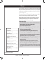
Hunter Fan 42686-01 is an addition to your home or office that will provide comfort and performance for many years. This installation and operation manual gives you complete instructions for installing and operating your fan. We are proud of our work and appreciate the opportunity to supply you with the best ceiling fan available anywhere in the world. This manual includes instructions for:
- Getting Ready
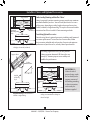
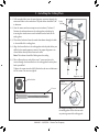
- Installing the Ceiling Plate
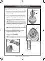
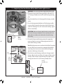
- Assembling the Fan
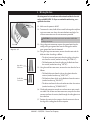
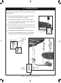
- Hanging and Wiring the Fan
- Installing the Canopy and Canopy Trim Ring
- Assembling the Blades
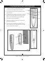
- Completing Your Installation With
Hunter Fan 42686-01 is an addition to your home or office that will provide comfort and performance for many years. This installation and operation manual gives you complete instructions for installing and operating your fan. We are proud of our work and appreciate the opportunity to supply you with the best ceiling fan available anywhere in the world. This manual includes instructions for:
- Getting Ready
- Installing the Ceiling Plate
- Assembling the Fan
- Hanging and Wiring the Fan
- Installing the Canopy and Canopy Trim Ring
- Assembling the Blades
- Completing Your Installation With


-
 1
1
-
 2
2
-
 3
3
-
 4
4
-
 5
5
-
 6
6
-
 7
7
-
 8
8
-
 9
9
-
 10
10
-
 11
11
-
 12
12
-
 13
13
-
 14
14


Hunter Fan 42686-01 User manual
- Category
- Household fans
- Type
- User manual
Hunter Fan 42686-01 is an addition to your home or office that will provide comfort and performance for many years. This installation and operation manual gives you complete instructions for installing and operating your fan. We are proud of our work and appreciate the opportunity to supply you with the best ceiling fan available anywhere in the world. This manual includes instructions for:
- Getting Ready
- Installing the Ceiling Plate
- Assembling the Fan
- Hanging and Wiring the Fan
- Installing the Canopy and Canopy Trim Ring
- Assembling the Blades
- Completing Your Installation With
Ask a question and I''ll find the answer in the document
Finding information in a document is now easier with AI
Related papers
-
 Hunter Fan 22434 Owner's manual
-
 Hunter Fan 25124 Owner's manual
-
 Hunter Fan 28714 Owner's manual
-
Hunter 21527 User manual
-
 Hunter Fan IN2TX13 User manual
-
Hunter Fan 27224 User manual
-
 Hunter Fan 27453 Owner's manual
-
 Hunter Fan 28728 Owner's manual
-
 Hunter Fan 21323 User manual
-
 Hunter Fan 25102 Owner's manual


