Page is loading ...

1
Operation & Service Manual
823209 2/01
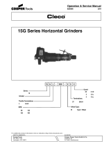
136 Reciprocating Saw
Spade
Handle:
X
136
Tool Type:
ReciprocatingR
VariableV
Speed:
136
Series:
XVR
NORTH AMERICA EUROPE
CooperTools
P.O. Box 1410
Lexington, SC 29071
Cooper Power Tools GmbH & Co.
Postfach 30
D-73461 Westhausen

2
Safety Recommendations
For your safety and the safety of others, read and understand the
safety recommendations before operating this saw.
Always wear protective equipment.
Caution: Faceshields do not provide unlimited protection against
flying particles and are not to be considered as eye protection. ANSI
Z87.1 states that separate eyewear shall be used. For additional
information on eye protection, refer to Federal OSHA Regulations,
29 CFR, Section 1910.133, Eye and Face Protection, and ANSI
Z87.1, Occupational and Educational Eye and Face Protection. This
standard is available from the American National Standards Insti-
tute, Inc., 11 West 42nd Street, New York, NY 10036.
Hearing protection is recommended in high noise areas (above 85
dBA). Close proximity of additional tools, reflective surfaces, pro-
cess noises, and resonant structures can substantially contribute
to the sound level experienced by the operator. Proper hearing con-
servation measures, including annual audiograms and training in
the use and fit of hearing protection devices may be necessary. For
additional information on hearing protection, refer to Federal OSHA
Regulations, 29 CFR, Section 1910.95, Occupational Noise Expo-
sure, and American National Standards Institute, ANSI S12.6, Hear-
ing Protectors.
Other protective clothing should be worn as required, unless it cre-
ates a greater hazard. Do not wear loose fitting clothing or any jew-
elry. Gloves can be caught in the the rotating blade causing severe
injury. Avoid inhaling dust resulting from the operation of this saw.
Wear approved respirator or mask if ventilation is inadequate. Res-
pirators should be selected, fitted, used and maintained in accor-
dance with Occupational Safety and Health Administration and other
applicable regulations.
This saw is designed to operate on 90 psig (6.2 bar) max. air pres-
sure. Installation of a filter-regulator-lubricator in air supply line is
highly recommended. Before tool is connected to air supply, check
throttle for proper operation, i.e., throttle moves freely and returns
to closed position. Clear air hose of accumulated dust and mois-
ture. Be careful not to endanger adjacent personnel. Before remov-
ing tool from service or changing blades, make sure air line is shut
off and drained of air. This will prevent tool from operating if throttle
is accidently engaged. Do not use tool to drain residual air from air
line. A self-relieving valve is recommended for this purpose.
Work Environment. Work areas should be kept clean and free
from clutter. Visitors should be kept away from work area. The air
hose should be suspended or placed to prevent damage to the
hose or inadvertent tripping to workers. An improperly placed hose
can be hooked by a vehicle or worker pulling the saw out of the
user’s hands or causing a loss of balance. After use the saw should
be disconnected properly and stored.
Safe Use. Keep both hands on the saw and away from the cutting
area while the blade is rotating. Blades should be kept sharp. Mate-
rials to be cut must be securely held to prevent movement. Be aware
that end pieces may fall after being cut, and care must be exer-
cised. Never use liquid coolants or cutting oils on the blade or band
mechanism. Damage may occur to the blade guides and pulley
tires. When cutting conduit or pipe, be certain that live electrical
wires and explosive and/or harmful gases or liquids are not present.
Some individuals may be susceptible to disorders of the hands and
arms when performing tasks consisting of highly repetitive motions
and/or exposure to extended vibration. Cumulative trauma disor-
ders such as carpal tunnel syndrome and tendonitis may be caused
or aggravated by repetitious, forceful exertions of the hands and
arms. Vibration may contribute to a condition called Raynaud’s Syn-
drome. These disorders develop gradually over periods of weeks,
months, and years. It is presently unknown to what extent
exposureorders develop gradually over periods of weeks, months,
and years. It is presently unknown to what extent exposure to vibra-
tions or repetitive motions may contribute to the disorders. Heredi-
tary factors, vasculatory or circulatory problems, exposure to cold
and dampness, diet, smoking and work practices are thought to
contribute to the conditions.
Tool operators should be aware of the following warning signs and
symptoms so that a problem can be addressed before it becomes a
debilitating injury. Any user suffering prolonged symptoms of tin-
gling, numbness, blanching of fingers, clumsiness or weakened grip,
nocturnal pain in the hand, or any other disorder of the shoulders,
arms, wrists, or fingers is advised to consult a physician. If it is
determined that the symptoms are job related or aggravated by
WARNING!
Impact resistant eye protection
must be worn while operating
or working near this tool.
CAUTION!
Personal hearing protection is
recommended when operating
or working near this tool.
WARNING
!
Wear respirator where
necessary.
Electrical and/or explosive hazard. Be
certain that the object being cut does not
contain electrical wires or gases.
WARNING
!
Repetitive work motions and/or vibration
may cause injury to hands and arms.
Use minimum hand grip force consistent
with proper control and safe operation.
Keep body and hands warm and dry.
Avoid anything that inhibits blood circulation.
Avoid continuous vibration exposure.
Keep wrists straight.
WARNING
!
Avoid repeated bending of wrists and hands.

3
Safety Recommendations
movements and postures dictated by the job design, it may be nec-
essary for the employer to take steps to prevent further occurrences.
These steps might include, but are not limited to, repositioning the
workpiece or redesigning the workstation, reassigning workers to
other jobs, rotating jobs, changing work pace, and/or changing the
type of tool used so as to minimize stress on the operator. Some
tasks may require more than one type of tool to obtain the optimum
operator/tool/task relationship.
The following suggestions will help reduce or moderate the effects
of repetitive work motions and/or extended vibration exposure:
• Use a minimum hand grip force consistent with
proper control and safe operation
• Keep body and hands warm and dry (cold
weather is reported to be a major factor con-
tributing to Raynaud’s Syndrome)
• Avoid anything that inhibits blood circulation
— Smoking Tobacco (another contribut
ing factor)
— Cold Temperatures
— Certain Drugs
• Tasks should be performed in such a manner
that the wrists are maintained in a neutral posi
tion, which is not flexed, hyperextended, or
turned side to side
• Stressful postures should be avoided — se-
lect a tool appropriate for the job and work lo
cation
• Avoid highly repetitive movements of hands and
wrists, and continuous vibration exposure (af-
ter each period of operation, exercise to in-
crease blood circulation)
• Keep tool well maintained and replace worn
parts (a preventative maintanance program
with scheduled inspections is highly recom-
mended)
This information is a compilation of general safety practices ob-
tained from various sources available at the date of production.
However, our company does not represent that every acceptable
safety practice is offered herein, or that abnormal or unusual cir-
cumstances may not warrant or require additional procedures. Your
work may require additional specific safety procedures. Follow these
procedures as required by your company. For more information,
see the latest edition of ANSI B186.1, Safety Code for Portable Air
Tools available from the American National Standards Institute, Inc.,
11 West 42nd Street, New York, NY 10036.
Extension
Neutral
Flexion Radial Deviation
Neutral Ulnar Deviation
Avoid Avoid
Avoid
OK Avoid OK
OVER
CAUTION!
Personal hearing protection is
recommended when operating
or working near this tool.
WARNING!
Impact resistant eye protection
must be worn while operating
or working near this tool.
Read Operating Instructions carefully. Follow
the Safety Recommendations for your safety
and the safety of others.
Hearing protection is recommended in high noise
areas (above 85 dBA). Close proximity of other
tools, reflective surfaces, process noises, and
resonant structures can substantially contribute
to the sound level experienced by the user.
WARNING
!
Repetitive work motions and/or vibration
can cause injury to hands and arms.
Use minimum hand grip force consistent with
proper control and safe operation.
Keep body and hands warm and dry.
Avoid anything that inhibits blood circulation.
Avoid continuous vibration exposure.
Keep wrists straight.
Avoid repeated bending of wrists and hands.
Do not remove this tag until
the operator of this tool has
read these safety precautions.
SAFETY
INSTRUCTIONS
1. Use eye and hearing protection.
2. Keep hands away from cutting
area.
3. Turn off air when not in use, when
changing or adjusting blades, or
servicing.
4. Secure work. Use clamps or vise
to hold work.
5. Stay clear of end pieces that may
fall after being cut off.
6. Keep blades sharp.
204203
204204
Electrical and/or explosive hazard. Be
certain that the object being cut does not
contain electrical wires or gases.
WARNING
!
204203 204204 204737

4
2. Insert the blade into the blade clamp until it bottoms.
When the blade is properly positioned: the hole in the blade
shank will align with the hole (B) Fig. 2, in the backside of
blade clamp.
Fig. 2
3. Firmly tighten clamp screw.
4. To remove blade, loosen blade clamp three to four turns
and pull blade from clamp.
PIVOTING GUIDE SHOE
The shoe (A) Fig. 3, serves as a rest while making a cut. It
is pivoted so the saw may be gradually raised to a position
perpendicular to the work as the saw is moved toward the
operator.
Do not operate the saw with the guide
shoe removed.
Fig. 3
READ SAFETY RECOMMENDATIONS
BEFORE CONNECTING TOOL.
OPERATING INSTRUCTIONS
The Cleco reciprocating saw is designed to operate on 90
psig (6.2 bar) maximum air pressure, using a 5/16" (8mm)
x 8' whip hose. If additional length is required, the next
larger hose size may be connected to the 8' whip hose.
The Cleco reciprocating saw is designed for cutting wood
up to 12" thick, metal up to 3/4" thick and various other
materials, such as plastics, fiberglass, hard rubber, etc.
The handle, gear housing, intermedi-
ate plate, blade and pivoting guide shoe
may be made live if the blade cuts into live wiring. To
prevent accidental electrical shock, all electricity to
material being cut must be completly shut off.
STARTING AND STOPPING SAW
Connect air supply. Depress throttle lever to start saw.
Releasing throttle lever will stop saw.
SELECTING THE BLADE
For best performance, longer blade life, and smoother cut,
select the proper blade for the job. A wide assortment of
blades are available.
When cutting metal always select a blade which will allow
at least three teeth to be engaged in the thickness of ma-
terial.
INSTALLING THE BLADE
Turn off air and bleed air hose before
installing or removing blades.
1. Use hex wrench to loosen blade clamp screw (A) Fig. 1,
by turning counterclockwise three to four turns.
Fig. 1
WARNING
!
WARNING
!
CAUTION
!

5
USING THE SAW
STARTING WORK
Consult the Blade Selector Charts for the blade best suited
for the material to be cut. For greatest economy, use the
shortest blade suitable for the thickness of the material to
be cut.
Be sure the material to be cut is rigid. Small work pieces
should be securely clamped in a bench vise or to a work
table. As the work progresses in scroll or curved cut-out
pieces, the material may be adjusted to accommodate the
movement of the saw. If the work is large enough, it may
be hand held across saw horses. The saw cuts freely with
only slight feed pressure. Forcing the saw will not make it
cut faster.
SAWING WOOD
The saw is used much the same as a hand saw in that it is
moved toward the operator during the cutting operation.
However, since the blade cuts on the up-stroke instead of
the down-stroke as in the case of the hand saw, the good
or finish side of the work should face down during the cut-
ting operation.
PLUNGE CUTS
The saw can be used for plunge cutting wood, plywood,
wallboard, and plastic materials. DO NOT attempt to plunge
cut metal.
Clearly mark line of cut on the work. Grasp front housing
with one hand and rear handle with the other hand. To start
cut, rest saw on shoe bracket, align blade with the marked
line of cut, (blade NOT touching work), as shown in Fig. 4.
Start saw. Using bracket as a pivot point, roll saw forward
by raising rear handle, as shown in Fig. 5. When blade has
cut through the work, continue raising the rear handle until
saw is perpendicular to the work surface. Keep saw in this
position and move blade along line of cut.
SAWING METAL
When cutting angle, H-beam, I-beam, channel, etc., start
the cut on the surface where the greatest number of teeth
will contact the work. To make a pocket cut, drill a starting
hole first. To extend blade life, cutting oil can be applied to
the work surface along the line of the cut.
Fig. 4
Fig. 5
MAINTENANCE
KEEP TOOL CLEAN
Periodically blow out all air passages with dry compressed
air. Remove build up of grime resulting from working green
or sappy wood. The rubber boot may be cleaned with a
soft damp cloth. NEVER use solvents, as they could pos-
sibly dissolve or otherwise damage the material.
LUBRICATION
An automatic in-line filter-lubricator is recommended as it
increases tool life and keeps the tool in sustained operation.
The in-line lubricator should be regularly checked and filled
with a good grade of 10W machine oil. Proper adjustment
of the in-line lubricator is performed by placing a sheet of
paper next to the exhaust ports and holding the throttle
open approximately 30 seconds. The lubricator is properly
set when a light stain of oil collects on the paper. Excessive
amounts of oil should be avoided.
STORAGE
In the event that it becomes necessary to store the tool for
an extended period of time (overnight, weekend, etc.), it
should receive a generous amount of lubrication at that
time and again when returned to service. The tool should be
stored in a clean and dry environment.

6
ALL-PURPOSE SAW BLADES
A blade for every type of sawing application; will cut smoothly and easily through wood, metal and composition material.
Blades designed for use on Porter-Cable, Cleco and most competive saws.
Proper Blade Selection for metal: ALWAYS select a blade where at least three teeth are engaged in the thickness of the
metal.
Porter-Cable
Blades
PORTER-CABLE BLADES

7
Porter-Cable
Blades

8
Replace if 3/16"
(4.7mm) or less
at either end.
DISASSEMBLY
HANDLE
Should the throttle valve seal 847426, need replacing,
unscrew the throttle valve cap 867753, for removal of the
throttle valve and components.
The tool is equipped with an air screen for protection of the
internal motor parts from foreign material. The air screen
located in the inlet bushing may be removed for cleaning
and inspection by unscrewing the inlet bushing 867758. If
the screen is torn or damaged, the inlet bushing should be
replaced. The throttle handle and motor housing, may be
removed for cleaning and inspection by unscrewing the two
(2) socket head cap screws and nuts after the tool is
disassembled to the point that the motor can be removed
to allow access to nuts inside motor housing.
MOTOR HOUSING & MOTOR
The front housing and intermediate plate 204683, must be
removed from motor housing to remove motor. Remove
four (4) hex cap screws holding the front housing and
intermediate plate to motor housing. The motor can be
pulled from motor housing. The "O"-rings and mufflers can
be removed from motor.
Use a suitable driver to drive the front rotor shaft out of the
front rotor bearing. After removing the cylinder and rotor
blades, the rear rotor shaft may be driven out of the rear
rotor bearing.
FRONT HOUSING & INTERMEDIATE PLATE
To disassemble the front housing 204692, from the inter-
mediate plate 204683, remove (4) four hex cap screws and
lift complete unit off the intermediate plate. The secondary
muffler can be removed for inspection.
REASSEMBLY
The tool is reassembled in the reverse order of disassem-
bly. Inspect all parts for damage or wear. It is recommended
that new rotor blades be installed at each repair cycle. If not
replaced, the used ones must measure a minimum of 3/16"
(4.7mm) at both ends.
Replace bearings that are rough or have excessive end
play. Install the front rotor bearing in the front bearing plate
and measure the distance from the face of the bearing plate
to the inner race of the bearing with the bearing race loaded
rearward. Select or fit by sanding, a rotor collar .001"
(.025mm) to .002" (.050mm) longer than this measure-
ment. Install the rotor blades, cylinder rear bearing plate,
and rear bearing on the rotor. After final assembly of the
motor unit, the cylinder should be held securely but not
tightly between the two plates. The rotor should not rub
either plate.
Note: Tighten 204727 locknuts holding handle to backhead,
to a maximum of 12 ft. lbs. of torque during reassembly.
Tighten all screws and nuts securely during reassembly.
Place a few drops of 10W machine oil in the air inlet to
ensure positive lubrication of all motor parts as soon as air
is applied.

9
RECIPROCATING SAW
HEAD
Part
No.
204203*
204204*
204675
204676
204677
204678
204679
204680
204681
204682
204683
204684
204685
204686
204687
204688
Name of Part
Safety Instruction Label
Warning Label
Intermediate Plate Bearing
Front Housing Bearing
Gear
Reciprocating Shaft
Blade Clamp
Blade Clamp Screw
Insulator Boot
Front Housing Screw
Intermediate Plate
Plate
Drive Shaft
Flat Washer
Wobble Plate
Retaining Ring
Part
No.
204689
204690
204691
204692
204693
204694
204695
204696
204697
204698
204699
204700
204701
204702
204703*
204704*
204759
Spacer
Carrier Tube Assembly
Felt Seal
Front Housing
Felt Seal
Shoe & Bracket Assembly
Shoe Screw
Carrier Tube Screw
Plug
Retaining Ring
Plate Screw
Oil Seal
Plug
O-Ring
Wrench
Wrench Holder
Housing Bolts
HOUSING PARTS LIST
Name of PartQty.
1
1
2
3
1
1
1
1
1
1
1
1
1
1
1
2
Qty.
1
1
1
1
1
1
2
1
1
1
2
1
1
1
1
1
4
204675
204703
204704
204675
204701
204676
204688
204689
204676
204687
204676
204698
204688
204685
204678
204702
204690
204691
204680
204699
204681
204694
204695
204696
204679
204677
204682
204683
204684
204693 204700
204686
204692
204697
204759
SAFETY
INSTRUCTIONS
1. Use eye and hearing protection.
2. Keep hands away from cutting
area.
3. Turn off air when not in use, when
changing or adjusting blades, or
servicing.
4. Secure work. Use clamps or vise
to hold work.
5. Stay clear of end pieces that may
fall after being cut off.
6. Keep blades sharp.
204203
204204
Electrical and/or explosive hazard. Be
certain that the object being cut does not
contain electrical wires or gases.
WARNING
!
* Parts not included in head. The complete head can be purchased using part no. 204738.

10
RECIPROCATING SAW MOTOR
PARTS LIST
RECIPROCATING SAW
MOTOR
Part No.
204222
204312
204712
812165
847525
847528
864489
864493
865417
869445
869448
869449
Name of Part
Rear Bearing Plate
Cylinder (incls. 812165)
Rotor
Cylinder Pin
Rotor Collar .124"
Front Rotor Bearing
Rotor Collar .122"
Rotor Collar .126"
Rotor Collar .128"
Rear Bearing
Front Bearing Plate
Rotor Blade
Qty.
1
1
1
1
*
1
*
*
*
1
1
4
* ONLY ONE ROTOR
COLLAR REQUIRED.
869445
847528
812165
869449
869448
204222
204312
204712
ROTOR COLLAR
PART NO. SIZE
864489 .122"
847525 .124"
864493 .126"
865417 .128"

11
864195
812977
867756
867758
867732
204720
204714
204711
Parts not included in
Subassembly - 201794
204708
204724
204715
204727
204706 204709
847426
204710
413056
833961
867753
612136
204707
864582
615643
204713
204715
QUANTITY
RECIPROCATING SAW HANDLE
AND
MOTOR HOUSING PARTS LIST
Motor Housing
Insert
Washer
Spacer
Throttle Valve
Motor Housing Plate
Throttle Bushing
Throttle Pin
Muffler
Handle
Muffler
Lock Nut
Throttle Valve Spring
Socket Head Cap Screw
"O"-Ring
Lever Stop Pin
"O"-Ring 13/16" x 1"
Throttle Valve Seal
Throttle Lever Pin
Throttle Lever
"O"-Ring 1-1/8" x 5/16"
Throttle Valve Cap
Throttle Pin Bushing
Inlet Bushing
1
2
2
1
1
1
1
1
3
1
1
2
1
2
1
1
1
1
1
1
1
1
1
1
204706
204707
204708
204709
204710
204711*
204713
204714
204715*
204720
204724*
204727
413056
612136
615643
812977
833961
847426
864195
864582
867732
867753
867756
867758
PART NO.
NAME OF PART
RECIPROCATING SAW
HANDLE AND
MOTOR HOUSING
SUBASSEMBLY
The complete handle and motor housing
can be purchased as a subassembly
using part no. 201794.
* Parts not included in handle and motor
housing subassembly.

12
CooperTools
670 Industrial Drive
Lexington, SC 29072
Phone: (803) 359-1200
Fax: (803) 359-2013
www.cooperindustries.com
/