Page is loading ...

1
TX22U -Wireless 915 MHz Thermo-hygro
transmitter
The TX-22U thermo-hygro transmitter measures the outdoor
temperature and humidity and also transfers the wind and rain data to
the weather station.
INVENTORY OF CONTENTS
1. One TX22U Thermo-hygro transmitter
2. Mounting hardware
3. Instruction manual and warranty card.
ADDITIONAL EQUIPMENT (not included)
•
Two fresh AA 1.5V batteries for the remote Thermo-hygro
transmitter, which in turn powers the wind speed sensor and the
rainfall sensor (No need to insert batteries to Wind and Rain
sensor.)
Important Notes on Set-up and Operation
• The Thermo-hygro transmitters both the source of power for both
outdoor sensors and source of transmission for all remote sensor
data.
• The Thermo-hygro transmitter should be placed in a dry, shaded
area. Avoid direct sun, as that will cause incorrect readings.
• Fog and mist will not harm your Thermo-hygro transmitter but
direct rain must be avoided.
The thermo-hygro sensor has a range of 330 feet. Keep in mind
that the 330 feet is in open air with no obstructions and that radio
waves DO NOT curve around objects. Actual transmission
range will vary depending on what is in the path of the signal.
Each obstruction (roof, walls, floors, ceilings, thick trees, etc.) will
effectively cut signal range in half.
Example: A wireless weather station with a 330 feet range is
mounted on an interior wall, so that the signal has to pass
through one interior wall, one exterior wall, and across the 10
feet width of the room between the 2 walls. The first wall will
reduce the range to 165 feet, and the second wall will reduce the
range to 87 feet. Factoring in the 10 foot room, this leaves a
maximum of 77 feet of remaining signal range.
This allowance is typically enough for a frame wall with non-
metallic siding; however certain materials can reduce range even
further. Metal siding, stucco, and some types of glass can
reduce signal range by as much as ¾ or more, compared to the
½ reduction typical of most obstructions. It is possible to receive
a signal through these materials, however maximum range will
be much less due to their tendency to absorb or reflect a much
larger portion of the sensor’s signal.
• The Thermo-hygro transmitter transmits a signal about every 4.5
seconds. After the batteries have been installed, the indoor
weather station will search for the signal for the duration of few
minutes. If there is no temperature or humidity reading in the
OUTDOOR LCD or wind speed in the WIND SPEED LCD after 5
minutes, user shall make sure the units are within range of each
other, or repeat the battery installation procedure.
• If a button is pressed before the indoor weather station receives
the signal from the Thermo-hygro transmitter, you will need to
follow the battery installation procedure again.
SETTING UP
Connection between the Thermo-hygro transmitter and
the Wind and Rain sensor
First user shall unwind the cables of the Rain and the Wind sensors.
Connect the Rain and the Wind sensors to the Thermo-hygro
transmitter by plugging the connector heads of the two sensors into
the appropriate sockets of the Thermo-hygro transmitter. Be sure they
“click” into place.
Battery Installation
REMOTE Thermo-hygro transmitter
1. Remove the mounting bracket and humidity hood.
2. Remove the battery cover by sliding the cover down.
3. Observing the correct polarity install 2 AA batteries. The
batteries will fit tightly (to avoid start-up problems make sure
they do not spring free).
4. Replace the battery cover by sliding upwards. Be sure battery
cover is on securely.
5. Replace the humidity hood.
Weather Station
1. Then insert the batteries into the Weather Station. Once the
batteries are installed, all segments of the LCD will light up
briefly and a short signal tone will be heard. It will then display
the time as 12:00, the date as 1.1.05, the weather icons, and air
pressure value. "- - -" will be shown for outdoor data.
2. Afterwards, the Weather Station will start receiving data from
the transmitter. The outdoor temperature, humidity wind chill
and wind speed should then be displayed on the Weather
Station. If this does not happen after 30 seconds, the batteries
will need to be removed from both units. You will have to start
again from step 1.
3. You may then check all cables for correct connection and all
components for correct function by manually turning the wind-
gauge, moving the weather-vane, tilting the rain sensor to hear
the impact of the internally moving seesaw, etc.
4. Time and date shall be manually set.
5. After the Weather Station has been checked for correct function
with regard to the above points and found fit, the initial set up of
the weather station system is finished and the mounting of the
system components can take place. It must be ensured
however that all components work properly together at their
chosen mounting or standing locations. If e.g. there appear to
be problems with the 915 MHz radio transmission, they can
mostly be overcome by slightly changing the mounting locations.
Note:
The radio communication between the receiver and the transmitter in
the open field reaches distances of max 330 feet (100 meters),
provided there are no interfering obstacles such as buildings, trees,
vehicles, high voltage lines, etc.
6. Radio interferences created by PC screens, cordless phones,
radios or TV sets can in some cases entirely cut off radio
communication. Please take this into consideration when
choosing standing or mounting locations.
Note:
•
After batteries are installed in transmitter, user shall also power
up the Weather station to receive the signal from the transmitter
as soon as possible. If the weather station is powered after
more than 5 hours the transmitter is powered, the weather
station will never receive signal successfully from this
transmitter. In this case, user will need to reinstall the batteries
from the transmitter to redo setting-up procedures.
•
Detailed Set up procedures of the Weather Station, the Relay
Transmitter, the Rain sensor and the Wind Sensor refer to the
main operation manual of WS- 1610.
MOUNTING
THE THERMO-HYGRO TRANSMITTER
The Thermo-hygro transmitter can be mounted in several ways:
• With the use of screws
• Using adhesive tape (Use Tape as a positioning tool only.)
• Using nylon straps
MOUNTING WITH SCREWS
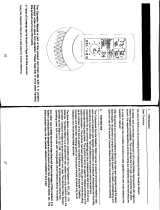
Sockets for Wind
and Rain sensor
Cable connection between
the wind sensor and the
thermo-hygro transmitter
Cable connection
between the rain
sensor and the
thermo-hygro
transmitter
Wireless transmission
at 915 MHz - thermo-
hygro transmitter to
weather station
Weather
Wind
Rain

2
1) Remove the mounting bracket from the Thermo-hygro
transmitter .
2) Place the mounting bracket over the desired location. Humidity
cap must be in the upright position.
3) Through the two screw holes of the bracket, mark the mounting
surface with a pencil.
4) Screw mounting bracket onto the mounting surface. Ensure
that the screws are tight against the bracket.
5) Insert the Thermo-hygro transmitter into the bracket.
MOUNTING WITH ADHESIVE TAPE
Two-sided tape is included only as a positioning tool while you test for
signal reception and properly position your sensor. Tape only should
not be used for mounting as the sensor may fall. Please secure with
screws or nylon straps.
MOUNTING WITH NYLON STRAPS
1) Remove the mounting bracket from the Thermo-hygro
transmitter.
2) Place two nylon straps through the slots on the mounting
bracket.
3) Place the Thermo-hygro transmitter in your desired mounting
location.
4) Fasten the two nylon straps securely around the mounting
location.
MAINTENANCE AND CARE
• Extreme temperatures, vibration, and shock should be avoided to
prevent damage to the units.
• Clean displays and units with a soft, damp cloth. Do not use
solvents or scouring agents; they may mark the displays and
casings.
• Do not submerge in water.
• Immediately remove all low powered batteries to avoid leakage and
damage.
• Opening the casings invalidates the warranty. Do not try to repair
the unit. Contact La Crosse Technology for repairs.
SPECIFICATIONS
Note:
Detailed Set up procedures of the
Weather Station, the Relay Transmitter, the Rain sensor and the Wind
Sensor refer to the main operation manual of WS-1610.
Weather data measuring range:
Outdoor and dew
point:
-40°F to +140°F with 0.2°F resolution (-
40°C to 59.9°C with 0.1°C resolution)
“OFL” displayed if outside this range
Outdoor relative
humidity measuring
range:
1% to 99% with 1% resolution (“- - “
displayed if < 1%; "99" displayed if
≥99%)
Transmission range: 330 feet (in open space)
Power Supply:
Thermo-hygro
transmitter :
2 x AA, IEC LR6, 1.5V
Battery life cycle: Approximately 12 months
Recommended
battery type:
Alkaline
Dimensions (H x W x D):
Thermo-hygro
transmitter
2.25" x 2.44" x 6.18"
(57.3 x 62 x 157 mm)
WARRANTY INFORMATION
La Crosse Technology, Ltd provides a 1-year limited warranty on this
product against manufacturing defects in materials and workmanship.
This limited warranty begins on the original date of purchase, is valid
only on products purchased and used in North America and only to
the original purchaser of this product. To receive warranty service,
the purchaser must contact La Crosse Technology, Ltd for problem
determination and service procedures. Warranty service can only be
performed by a La Crosse Technology, Ltd authorized service center.
The original dated bill of sale must be presented upon request as
proof of purchase to La Crosse Technology, Ltd or La Crosse
Technology, Ltd’s authorized service center.
La Crosse Technology, Ltd will repair or replace this product, at our
option and at no charge as stipulated herein, with new or
reconditioned parts or products if found to be defective during the
limited warranty period specified above. All replaced parts and
products become the property of La Crosse Technology, Ltd and must
be returned to La Crosse Technology, Ltd. Replacement parts and
products assume the remaining original warranty, or ninety (90) days,
whichever is longer. La Crosse Technology, Ltd will pay all expenses
for labor and materials for all repairs covered by this warranty. If
necessary repairs are not covered by this warranty, or if a product is
examined which is not in need or repair, you will be charged for the
repairs or examination. The owner must pay any shipping charges
incurred in getting your La Crosse Technology, Ltd product to a La
Crosse Technology, Ltd authorized service center. La Crosse
Technology, Ltd will pay ground return shipping charges to the owner
of the product to a USA address only.
Your La Crosse Technology, Ltd warranty covers all defects in
material and workmanship with the following specified exceptions: (1)
damage caused by accident, unreasonable use or neglect (including
the lack of reasonable and necessary maintenance); (2) damage
occurring during shipment (claims must be presented to the carrier);
(3) damage to, or deterioration of, any accessory or decorative
surface; (4) damage resulting from failure to follow instructions
contained in your owner’s manual; (5) damage resulting from the
performance of repairs or alterations by someone other than an
authorized La Crosse Technology, Ltd authorized service center; (6)
units used for other than home use (7) applications and uses that this
product was not intended or (8) the products inability to receive a
signal due to any source of interference.. This warranty covers only
actual defects within the product itself, and does not cover the cost of
installation or removal from a fixed installation, normal set-up or
adjustments, claims based on misrepresentation by the seller or
performance variations resulting from installation-related
circumstances.
LA CROSSE TECHNOLOGY, LTD WILL NOT ASSUME LIABILITY
FOR INCIDENTAL, CONSEQUENTIAL, PUNITIVE, OR OTHER
SIMILAR DAMAGES ASSOCIATED WITH THE OPERATION OR
MALFUNCTION OF THIS PRODUCT. THIS PRODUCT IS NOT TO
BE USED FOR MEDICAL PURPOSES OR FOR PUBLIC
INFORMATION. THIS PRODUCT IS NOT A TOY. KEEP OUT OF
CHILDREN’S REACH.
This warranty gives you specific legal rights. You may also have other
rights specific to your State. Some States do no allow the exclusion of
consequential or incidental damages therefore the above exclusion of
limitation may not apply to you.
For warranty work, technical support, or information contact:
La Crosse Technology
2809 Losey Blvd. S.
La Crosse, WI 54601
Phone: 608.782.1610
Fax: 608.796.1020
e-mail:
support@lacrossetechnology.com
(warranty work)
sales@lacrossetechnology.com
(information on other products)
web:
www.lacrossetechnology.com
All rights reserved. This handbook must not be reproduced in any
form, even in excerpts, or duplicated or processed using electronic,
mechanical or chemical procedures without written permission of the
publisher.
This handbook may contain mistakes and printing errors. The
information in this handbook is regularly checked and corrections
made in the next issue. We accept no liability for technical mistakes
or printing errors, or their consequences.
All trademarks and patents are acknowledged.
/