Page is loading ...

Homeowner’s
Installation and
Operating Manual
SAFETY NOTICE: IF THIS APPLIANCE IS NOT PROPERLY INSTALLED, OPERATED AND MAIN-
TAINED, A HOUSE FIRE MAY RESULT.
TO REDUCE THE RISK OF FIRE, FOLLOW THE INSTALLATION INSTRUCTIONS. FAILURE TO
FOLLOW INSTRUCTIONS MAY RESULT IN PROPERTY DAMAGE, BODILY INJURY OR EVEN
DEATH. CONTACT LOCAL BUILDING OFFICIALS ABOUT RESTRICTIONS AND INSTALLATION
INSPECTION REQUIREMENTS IN YOUR AREA.
Do Not Discard This Manual: Retain for Future Use
2000941 3/07 Rev. 17
WinterWarm
Fireplace Insert
or System
For Use in North America
0941
Winter Warm Cover
3/01

2
WinterWarm Fireplace Insert or System
2000941
Introduction
Thank you for purchasing a Vermont Castings’ WinterWarm, an efficient fireplace carefully engineered to bring you the
latest in wood combustion principles and modern foundry technology.
The WinterWarm masonry Fireplace Insert turns a traditional masonry fireplace into a powerful heater; the Winter-
Warm Fireplace System combines an insulated metal cabinet with the Fireplace Insert so that it may be installed in
close-clearance situations where no masonry fireplace and chimney exists.
Whichever you have purchased, you can count on years of comfortable heating and pleasureable fire viewing if you
treat it properly and operate it according to the directions in this owner’s guide.
The WinterWarm Fireplace Insert, and the WinterWarm Fireplace System that utilizes the WinterWarm Fireplace
Insert, are listed by Underwriter’s Laboratories of Canada, and are in compliance with the standards set forth by the
Federal Environmental Protection Agency, 40 CFR Part 60.532(b), as stated on the permanent label attached to each
appliance.
This manual describes the installation and operation of the WinterWarm catalytic-equipped wood heater. This heater
meets the U.S. Environmental Protection Agency’s emission limits for wood heaters sold after July 1, 1990. Under
specific test conditions this heater has been shown to deliver heat at a rate ranging from 10,300 to 30,000 Btu’s/hr.
For more complete details on WinterWarm performance and specifications, please refer to page 3.
The WinterWarm is designed, tested and listed for burning wood. Do not burn other fuels.
We recommend that you hire a professional installer certified by Wood Energy Technical Training (WETT) to install
your WinterWarm, or to advise you on the installation should you attempt to install it yourself.
Please read the appropriate sections of this manual before you install and use your WinterWarm. For information on
the installation of a WinterWarm into a masonry fireplace, read Sections III and V. To learn how to install the Winter-
Warm and its Cabinet that make up the fireplace system, read Sections IV and V. For information on Operation and
Maintenance of the WinterWarm, read Sections I and II.
Failure to follow instructions may result in property damage, bodily injury or even death.
Save These Instructions For Future Reference
Before you begin, here’s a timesaving tip
on using this manual.
• To learn how to operate and maintain the Winter-
Warm, read Sections I and II.
• To install a WinterWarm Fireplace Insert into a
masonry fireplace, read Sections III and V.
• To install a WinterWarm Fireplace System, read
Sections IV and V.
Table of Contents
Introduction .................................................... 2
Specifications ................................................
3
Operation .......................................................
4
Maintenance ..................................................
9
Preparing a Masonry Chimney ....................
16
Installing the Fireplace System Cabinet ......
21
Appendices ..................................................
38
Proposition 65 Warning: Fuels used in gas, wood-
burning or oil fired appliances, and the products of
combustion of such fuels, contain chemicals known
to the State of California to cause cancer, birth de-
fects and other reproductive harm.
California Health & Safety Code Sec. 25249.6

3
WinterWarm Fireplace Insert or System
2000941
Specifications
Range of heat output* ............. 10,300 - 30,000 BTU/hr
Maximum heat output** ..........................50,000 BTU/hr
Area heated*** ................ Up to 1500 sq. ft. (140sq. m)
Size of wood splits ....................... 20-24” (508-610 mm)
Fuel Capacity .......................................... 40lbs. (18 kg)
Loading ..................................................................Front
Flue size .................................................... 8” (203 mm)
Fireplace Insert weight ........................ 475lbs. (216 kg)
Fireplace System weight ..................... 840lbs. (380 kg)
Primary Air Control ........................Manual/thermostatic
Secondary Air Control ............................Self-regulating
Glass panel ......................... High-temperature ceramic
Flue exit position ..................................................... Top
Blower rating ...............................106cfm. (115V, 60Hz)
*Under specific test conditions used during EPA emis
-
sions standard testing.
**This value can vary depending on how the unit is
operated, and the type and moisture content of the fuel
used. Figure shown is based on maximum fuel con-
sumption obtained under laboratory conditions and on
average efficiencies.
***These values are based on operation in building-
code conforming homes under typical winter climate
conditions in New England. If your home is of nonstan-
dard construction (e.g. unusually well insulated, not in-
sulated, built under ground, etc.) or if you live in a more
severe or more temperate climate, these figures may
not apply. Since so many variables affect performance,
consult your Vermont Castings’ Authorized Dealer to
determine realistic expectations for your home.
WinterWarm
37"
(959 mm)
26"
(676 mm)
8" (203 mm)
12
"
(327 mm)
12
"
(327 mm)
15"
(394 mm)
4"
(121 mm)
21
"
(553 mm)
6"
(172 mm)
7"
(200 mm)
36"
(914 mm)
7" (191 mm)
29
"
(759 mm)
25"
(648 mm)
41"
(1041 mm)
0941
Winter Warm
Specs
3/27/01 djt
13"
(349 mm)
7"
(200 mm)
15"
(403 mm)
23"
(603 mm)
18" (470 mm)
33” (838 mm)
Top View / System Cabinet
Fig. 1 WinterWarm dimensions.

4
WinterWarm Fireplace Insert or System
2000941
Section I Operation
Your WinterWarm’s Controls
and What They Do
Three controls regulate the performance of your Win-
terWarm: A primary air control supplies oxygen for the
fire, a damper directs air flow within the fireplace, and
a variable-speed fan control, or rheostat, regulates the
warm air flow into the room. (Fig. 2)
Primary Air Control
A single air control regulates the amount of heat the fire
will produce and how long it will burn.
The primary air control is located above the upper left
corner of the door. It is the top-most of the two brass-
capped controls located there (the brass knob on the
bottom regulates the fan), and is the primary source of
air for starting, maintaining, and reviving the fire.
Generally, more air entering the stove makes the fire
burn hotter and faster, while less air prolongs the burn.
The WinterWarm’s air supply is open to the maximum
when the control lever is moved to the left, and closed
when moved to the far right. It may be set anywhere
between the two extremes, however, depending on the
amount of heat desired.
To complement the manual setting of the air control, the
WinterWarm has an internal automatic thermostat that
ensures an even delivery of heat at the manual setting
you select.
The Damper
The damper directs air flow within the fireplace.
The damper is operated by moving the lever located
above the upper right corner of the door. It has two
positions: Open, to start or revive the fire (Fig. 3); and
closed (Fig. 4), for normal operation. The damper is
open when the lever is to the far left, and closed when
to the far right. There are no intermediate settings for
damper position.
When the damper is closed, the front door automatically
locks to prevent the door being inadvertently opened
when the fireplace is in its catalytic mode. This could
cause smoke to spill into the room.
To open the damper, lift up on the lever and move it
to the far left. The lock will disengage, allowing you to
open the front door.
To close the damper, move the lever to the right,
continuing past the resistance to lock the damper in
position. (The door handle must be positioned vertically
before the lock mechanism will engage.)
FP1070
Winter Warm Controls
3/01
Primary Air Control (Top Lever)
Fan Speed Control
(Rheostat) (Bottom
Lever)
Damper Control
Door Handle
Optional Outside
Air Control
FP1070
Fig. 2 All WinterWarm controls are located conveniently on
the front.
FP1072
WW
damper closed
3/27/01 djt
Damper Closed
Catalytic
Combustor
FP1072
Fig. 4 Damper is closed: Smoke is channelled through the
catalytic combustor where much of it can be burned.
FP1071
WW
damper open
3/27/01 djt
Damper
Open
FP1071
Fig. 3 The damper is open; Smoke is vented directly to the
chimney.

5
WinterWarm Fireplace Insert or System
2000941
The Fans
Two fans deliver a steady stream of warm air.
Heated air from your WinterWarm is forced into the
room by two internal fans. The control for the fans is
below the brass primary air control knob, just above the
upper left corner of the door. (Fig. 5)
“Off” is to the far left.
“High” is just to the right of “Off.”
“Low” is to the far right.
Variable adjustment of the fans is possible with any set-
ting between “high” and “low.”
For best results, coordinate fan speed with the setting
of your thermostat. For example, when the thermostat
lever is set at “low,” also set the fans at “low.” With the
thermostat set for maximum heat, set the fans at “high.”
FP1073
Winter Warm
fan/air settings
3/27/01 djt
Air Control Lever,
High Air Setting
Medium
Low Air Setting
Fan Control
Lever (Fan Off)
Fan On
FP1073
Fig. 5 Variable settings for both the fans and the air control
are possible between the two extreme settings.
Burn Only High-Quality Wood
The WinterWarm is designed to burn natural wood
only; do not burn fuels other than that for which it was
designed.
You’ll enjoy the best results when burning wood that
has been adequately air-dried. Avoid burning “green”
wood that has not been properly seasoned.
The best hardwood fuels include oak, maple, beech,
ash, and hickory that has been split, stacked, and air-
dried outside under cover for at least one year.
For areas that do not have a supply of hardwood, com-
monly burned softwoods include tamarack, yellow pine,
white pine, Eastern red cedar, fir, and redwood. These
too should be properly dried. Your WinterWarm will
accept wood up to 24” (610mm). Longer wood pieces
work better than short ones.
Wood should be stored under cover to maintain dry
-
ness, and should be dried at least six months for
optimum heating and fire-viewing performance. Even
for short-term storage, however, keep wood a safe
distance from the heater and keep it out of the areas
around the heater used for refueling and ash removal.
Use the Air Control Settings
that Work Best for You
No single air control setting will fit every situation. Each
installation will differ depending on the quality of the
fuel, the amount of heat desired, and how long you wish
the fire to burn.
The control setting also depends on your particular
installation’s “draft,” or the force that moves air from the
stove up through the chimney. Draft is affected by such
things as the length, type, and location of the chimney,
local geography, nearby obstructions, and other factors.
Too much draft may cause excessive temperatures in
the WinterWarm, and could even damage the com-
bustor. On the other hand, too little draft can cause
backpuffing into the room and/or the “plugging” of the
chimney or combustor.
How do you know if your draft is excessively high or
low? Symptoms of too much draft include an uncon-
trollable burn or a glowing-red part of the WinterWarm
front. A sign of inadequate draft is smoke leaking into
the room through the stove or chimney connector joints,
low heat, and dirty glass.
In some newer homes that are well-insulated and
weather-tight, poor draft may result from insufficient air
in the house. In such instances, an open window near
the stove on the windward side of the house will provide
the fresh air needed.
Another option for getting more combustion air to the
stove is to duct air directly from the outside to the stove.
In fact, in some areas provisions for outside combustion
air are required in all new construction.
Your WinterWarm is designed so that it is possible to
incorporate outside air for combustion. Directions for
installing the optional outside air duct may be found
beginning with Step 4 on Page 31.
When first using the stove, keep track of the settings
of the air controls. You will quickly find that a specific
setting will give you a fixed amount of heat. It may take
a week or two to determine the amount of heat and the
length of burn you should expect from various settings.
Most installations do not require a large amount of
combustion air, especially if adequate draft is available.
Do not for any reason attempt to increase the firing
of your heater by altering the air control adjustment
range outlined in these directions.

6
WinterWarm Fireplace Insert or System
2000941
Use the following air control settings as a starting point
to help determine the best settings for your installation.
Each is described as a fraction of the total distance the
lever may be moved from right to left.
WinterWarm Control Settings
Burn Rate Primary Air Control
Low From far right to 1/3
the distance to left
Medium From 1/3 to 2/3 the distance
to left
High From 2/3 the distance
to left to far left
How To Build a Wood Fire and
Keep It Going
A WinterWarm leaves the factory with the combustor
installed.
In the United States, it is against the law to operate this
wood heater in a manner inconsistent with operating
instructions in this manual, or if the catalytic combustor
is deactivated or removed.
High-Efficiency Wood Burning
with Catalytic Combustion
The components of the catalytic combustion system in
your WinterWarm work together to produce optimum
conditions for secondary combustion.
When the damper is closed, smoke is directed through
the catalytic element, which causes ignition of smoke
at temperatures of 500-600°F (260-315°C), half the
temperature normally required for unaided secondary
combustion.
The catalytic element is a ceramic “honeycomb” coated
with the catalytic material. The element is located in
the secondary combustion chamber, molded from a
special high-temperature insulating refractory mate-
rial. The design of the chamber provides the correct
environment necessary for secondary combustion of
the fuel (smoke).
Catalytic combustion is activated by closing the damp-
er, thereby exposing the smoke to the combustor.
Closing the stove damper may also reduce the draft, so
to avoid putting out the fire or deactivating the combus-
tor, close the damper only when a fire is well-estab-
lished. When starting a fire, wait until the fire is well
established and there is an ember bed of at least 3-4”
(76 - 102mm) before closing the damper.
Never kindle a fire with colored paper or paper that
has colored ink or a glossy surface, and never burn
treated wood, garbage, solvents, or trash. All of these
may poison the catalyst and prevent it from operating
properly. Never burn cardboard or loose paper except
for kindling purposes. Never burn coal; doing so can
produce soot or large flakes of char or fly ash that can
coat the combustor and cause smoke to spill into the
room. Coal smoke also can poison the catalyst so that it
won’t operate properly.
In general, the fire must be sufficiently well-established
to ensure that catalytic activity is initiated. When first
starting a fire, a medium- to high- firing rate must be
maintained for at least twenty minutes. This ensures
that the stove, catalyst, and fuel are all stabilized at the
proper operating temperatures.
Even though it is possible for the fire to get quite hot
within a few minutes after a fire is started, the combus
-
tor may stop working or the fire may go out if the fire
is allowed to die down immediately as a result of the
damper being closed. Once the combustor starts work-
ing, heat generated by burning the smoke will keep it
working.
To determine whether the combustor is operating, ob
-
serve the amount of smoke leaving the chimney when
the damper is activated and when it is not. This proce-
dure is described on Page 12.
Starting and Maintaining a Wood Fire
Burn solid wood fuel only in the WinterWarm, and
burn it directly on the grate. Do not elevate the fuel.
Do not burn coal or other fuels.
Cast iron is a superior material for solid fuel stoves but
it must be treated with respect. It is extremely strong,
but can be broken with a sharp blow from a hammer or
from the thermal shock of rapid and extreme tempera-
ture changes.
The cast plates expand and contract with changes in
temperature. Minimize thermal stress by allowing the
plates to adjust gradually during an initial break-in fire
by following Steps 1-3 below.
Always be certain that the damper is open when start-
ing a fire or when refueling. This rule is easy to re-
member, as the WinterWarm’s integrated door/damper
interlock design does not permit opening the door unless
the damper is already open. To open the damper, lift up
on the lever and move it to the left. (Fig. 6)
WARNING: Operate your WinterWarm only with
the door fully closed and either the glass panel or
spark screen in place. If the door is left partially
open, gas and flame may be drawn out of the
fireplace opening, creating risks of both fire and
smoke.

7
WinterWarm Fireplace Insert or System
2000941
FP1074
Winter Warm
damper settings
3/27/01 djt
Open
Closed
Damper Control Lever
FP1074
Fig. 10 When the damper is closed, the front door automati-
cally locks to prevent opening while a fire is burning.
1. Open the stove damper, and open the primary air
control fully.
2. Lay some crumpled newspapers on the bottom
grate. Place on the paper six or eight pieces of dry,
finely-split kindling. On the kindling lay two or three
larger sticks of split dry wood approximately 1-2”
(25-51mm).
Do not use chemicals or fluids to start the fire. Do
not burn garbage or flammable fluids such as gaso-
line, naptha, or engine oil.
Also, never use gasoline-type lantern fuel, kerosene,
charcoal lighter fluid, or similar liquids to start or “fresh-
en up” a fire in this heater. Keep all such liquids well
away from the heater while it is in use.
3. Light the newspaper and close the door. Gradually
build up the fire by adding a few 3-5” (76 - 127mm)
diameter splits.
If this is your initial break-in fire, let the fire burn brightly,
but not to excess. Control the fire’s intensity by adjust-
ing the air control lever. After an hour or so stop adding
wood so that the fire dies out gradually.
For ongoing operation after the initial break-in, continue
to add a few sticks at a time of a progressively larger
size. Be sure to keep the fuel load behind the front
grate bar at all times. Continue until you have a live
ember bed at least 3-4” (76 - 102mm) deep. This may
take an hour or longer, particularly when the Winter-
Warm is vented to an exterior masonry chimney or
when you are just starting a fire.
You’ll soon find out that the WinterWarm is HOT WHILE
IN OPERATION! KEEP CHILDREN, CLOTHING, AND
FURNITURE AWAY. CONTACT MAY CAUSE SKIN
BURNS.
NOTE: Some chimneys need to be “primed,” or
warmed up, before they will draw sufficiently to start
a fire. To correct this situation, roll up a couple pieces
of newspaper, place them on top of the kindling and
toward the back of the stove, light them, and close the
doors. This should heat the chimney enough to initiate
a draft.
Once the draft is established, open the front door and
light the rest of the fuel from the bottom. Do not light the
main bed of fuel until the chimney begins drawing, and
repeat the procedure as often as necessary if the initial
attempt is unsuccessful.
4. Once a good ember bed of at least 3-4” (76 -
102mm) has formed, close the damper to activate
the combustor. To ensure continued operation of the
combustor, let the fire burn hot for an additional ten
to fifteen minutes after the damper is closed.
5. Close the primary air control to a medium-low set
-
ting, or about 1/3 the distance from right to left in
its travel range as described on Page 4. The fire
volume will diminish immediately, but the Winter-
Warm will continue to heat up. Maintain control of
the fire using the primary air control, and remember:
reduce the setting for less heat, increase the setting
for more heat. Refer back to the air control settings
chart on Page 4 for recommended settings at differ-
ent burn rates.
DO NOT OVERFIRE THIS HEATER. Overfiring may
cause a house fire, or can result in permanent damage
to the stove and to the catalytic combustor. If an exte-
rior part of the WinterWarm glows, you are overfiring.
Reloading and Reviving a Wood Fire
Open the stove damper, set the air control on “High,”
and wait at least fifteen seconds for the draft to in-
crease. Open the door slowly.
Check the ash level, and empty the ash pan if neces-
sary. Replace the pan.
Add the fuel, smaller pieces first. If it is necessary to
use wood smaller than the 24” (610mm) optimum size,
be sure to fill the firebox as completely as possible
by loading the wood pieces alternately on the left and
right. Split wood will fill the firebox more completely and
reduce the frequency of reloading.
If you have an ember bed of at least 3 - 4” (76 -
102mm), leave the damper open and the thermostat
set on “high” for 10-15 minutes, then close the damper.
If the ember bed is less than 3 - 4” (76 - 102mm), you
may have to let it burn longer.
Finally, adjust the air control and fan speed for your
desired heat level.

8
WinterWarm Fireplace Insert or System
2000941
NOTE: If the charcoal bed is relatively thick and your
fuel is well-seasoned, it is possible to add fresh fuel
(smaller pieces first), close the door and damper, and
reset the air control within five minutes.
Special Tactics for Cold-Climate Heating
The WinterWarm is capable of producing up to 50,000
Btu’s/hour and heating an area of up to 1,500 ft.
2
(140
m
2
) However, many factors affect heating performance
and can influence the extent to which the WinterWarm
can heat a given area.
A well-insulated home, located in a moderate climate
and with the WinterWarm Fireplace Insert or Fireplace
System located centrally in an open floor plan, will be
easier to heat than a drafty home in the far north in
which a WinterWarm is installed on an exterior wall at
the end of a long house.
In Fireplace Insert installations, over-sized chimneys
can produce less effective results than those that are
properly sized, and interior chimneys usually perform
better than those located outside the house.
Different results may be experienced even in the same
installation if you switch from burning good, dry wood to
wood that is partially rotted or inadequately seasoned.
To compensate for these factors in cold climates, it may
be necessary to operate the WinterWarm for longer
periods of time than described above before closing the
damper, or to leave the air control set to a higher level
more of the time.
Open-Fire Viewing
with the Screen Cassette
The cassette screen that was included with your Win-
terWarm is interchangeable with the glass cassette, en-
abling you to convert from closed-door wood burning to
protected open-fire viewing. Always leave the damper
open when operating the WinterWarm with the screen
in the open-fire mode.
To change cassettes, use this procedure:
Let the WinterWarm cool completely
• Open the door
• Loosen the two short retainer clips, one at each
top corner of the cassette frame, and turn them to
clear the frame.
• Tilt the top edge of the cassette away from the
door frame.
• Carefully remove the cassette, being especially
careful with the glass cassette. Store the unused
cassette for future use.
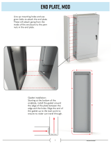
• Examine the gasket that seals the cassette to the
perimeter of the door frame. Contact your local
dealer if you need a replacement gasket.
• Check the bottom channel of the door frame for
debris, and clean if necessary.
• Insert the new cassette, bottom edge first, then
the top edge.
IMPORTANT: The glass used in your WinterWarm is
coated with a special material on one side that reflects
heat back into the fire chamber. Before replacing a
glass cassette that has been removed, examine the
metal frame. One side has smooth, mitered corner
joints; the other side has rough weld marks.
To install the glass correctly, the smooth mitered
corners must be facing the gasket and the rough weld
marks must be positioned toward the fire chamber.
• Replace the two retainer clips, applying just
enough pressure to secure the cassette evenly
against the gasket.
Remove and Store Ash Safely
Check the ash pan before reloading the stove, and
empty if necessary using the following procedure:
• Open the damper
• Open the load door (Fig. 7)
• Pull open the ash chamber door with the hooked
end of the fall-away handle.
• If the ash level is nearing the top, place the
removable cover over the pan and make sure it is
completely engaged. Ash may contain hot coals
and must be treated with extreme care.
• Take the pan outdoors and empty the ash into
your ash container.
FP1075
Remove ash pan
3/28/01 djt
FP1075
Fig. 7 Carefully remove ash pan.

9
WinterWarm Fireplace Insert or System
2000941
• Before replacing the ash pan, clear away any ash
that has spilled over the sides and back of the
pan.
• Replace the ash pan and close the ash door and
front door.
Empty the ash pan regularly, typically every one to
three days. The frequency will vary depending on how
you operate your WinterWarm: You burn more wood
at higher heat output settings, and ash will accumulate
faster.
Ash should be removed frequently and placed outdoors
in a metal container with a tight-fitting lid. The closed
container of ash should be placed on a noncombustible
floor or on the ground, well away from all combustible
materials, pending final disposal. If the ash is disposed
of by burial in soil or otherwise locally dispersed, it
should be retained in the closed container until all cin-
ders have thoroughly cooled. -Wood ash may be used
as a garden fertilizer.
CAUTION: Never use your household or shop vacuum
cleaner to remove ash from the fireplace; always re-
move and dispose of the ash properly.
Section II Maintenance
Keep your WinterWarm Looking New
and Working Its Best
Care of the Cast Iron Surface
An occasional dusting with a dry rag will keep the
painted cast iron of your WinterWarm looking new.
If the paint needs retouching, first allow the surface
to cool completely. Wire-brush areas needing to be
painted. Touch-up with high temperature stove paint
available from your local dealer. Apply the paint spar-
ingly. Two light coats are better than one heavy one.
Care of the Porcelain Enamel Surface
Use a soft brush as necessary. Do not use water or
other liquids on your WinterWarm. Fingerprints usually
can be buffed off porcelain enamel with a dry, soft cloth.
If marks remain, allow the WinterWarm to cool com-
pletely, then buff with a slightly damp, soft cloth. Dry
completely before starting a fire to avoid streaking.
Never use abrasives or harsh chemical cleaners on the
porcelain enamel finish. The enamel may scratch and
expose the cast iron, which can then stain or rust. If
you must remove spills or stains from porcelain sur-
faces, make sure that the fire is out and that the Win-
terWarm has cooled completely before cleaning. Use a
kitchen appliance cleaner and polish especially formu-
lated for enamel surfaces. Apply the cleaner sparingly
with a soft cloth, and buff away all traces.
Cleaning the Glass
The WinterWarm glass system requires a minimum
amount of cleaning. Most carbon deposits that accumu-
late will burn off during hot fires.
Ash residue that accumulates on the glass should be
removed periodically to prevent etching. To clean the
glass, follow this procedure:
• Be sure the glass is completely cool.
• Cleaning with water will work in most cases. Use
a glass cleaner especially made for this purpose
only if deposits are especially heavy. (If heavy
deposits are a frequent occurrence, however,
evaluate your operating techniques.)
• Rinse the glass thoroughly.
• Dry the glass completely.
NOTE: The WinterWarm glass is coated with a
special material on one side that helps reflect heat
back into the fire chamber. Do not attempt to re-
move this coating.

10
WinterWarm Fireplace Insert or System
2000941
Adjust the Door Latch Periodically
The front door of the WinterWarm should close securely
to prevent accidental opening and should close tightly
to prevent air from leaking into the fire chamber. The
door handle will be positioned vertically when the door
is closed.
Over a period of time, the gasket around the door will
compress and the latch may need adjustment. To adjust
the handle, follow this procedure (Fig. 8):
1. Loosen the small lock nut with a wrench.
2. Extend the striker screw one turn by turning it with
an Allen wrench.
3. Re-tighten the lock nut, while at the same time hold
-
ing the striker screw with the Allen wrench to prevent
its turning.
Test the door seal. Close the door on a dollar bill and
attempt to pull it free. If the bill is freed with little resis-
tance, the gasket isn’t snug enough at that spot. Contin-
ST531
Door Pawl
11/00
Small
Locking Nut
Large
Locking
Nut
Pawl
Striker Screw
Set Screw
Handle Stub
ST531
Fig. 8 An adjustable latch lets you restore a tight seal to the
WinterWarm’s door.
ue to make small adjustments until the setting is right.
If additional adjusting of the latch does not enable the
door to seal sufficiently in one area, try “adjusting” the
gasket in that area. Pack more cement or a smaller
diameter gasket into the channel beneath the gasket so
the main gasket is raised and makes contact with the
door frame. This procedure should solve the problem.
If it doesn’t, replace the gasket following the directions
below.
How to Replace Gaskets
Your WinterWarm uses rope-type fiberglass gaskets
to make a tight seal between some parts. With use, par-
ticularly on those parts that move, gaskets can become
brittle and compressed and can begin to lose their ef-
fectiveness. These will need periodic replacement.
All of the gaskets used are made of fiberglass. The
three sizes of replaceable gasket are listed below,
along with their application.
Replaceable WinterWarm Fiberglass Gaskets
Gasket Size... ...And The Parts It Seals
1/2” The door to the front (#1)
1/2” The door to the front edge of
the grate (#2)
3/16” The cassette glass seal to
the door (#3)
3/8” The damper to the upper
fireback (#4)
FP1076
WinterWarm
door parts
3/28/01 djt
Short Re-
tainer Clips
Welded
Corner
Toward
Firebox
Long Retainer
Clips
#3 Gasket
#2 Gasket
#1 Gasket
FP1076
Fig. 9 Front door components allow replacement of the
glass, gaskets or both.
Should you need to change a replaceable gasket, wait
until the fire is out and the stove has cooled. Be sure to
follow the standard safety procedure for working with
dusty materials: Wear safety goggles and a dust mask.
The procedure for replacing gaskets is the same,
regardless of the gasket location. Four easily-accom-
plished steps are involved:
1. Remove the existing fiberglass gasket by grasping
an end and pulling firmly.
2. Use a wire brush or the tip of a screwdriver to clean
the channel of any remaining cement or bits of gas-
ket.
3. Apply a thin bead of stove cement to the newly-
cleaned groove.
4. Pack a new gasket into the groove. Wait until you
have placed all but a couple inches from the end
before you trim the end to an exact fit.

11
WinterWarm Fireplace Insert or System
2000941
Replacing the Door Gaskets
Remove the door by lifting it straight up off its hinge
pins. Lay it face down on a padded surface.
Follow steps 1-4 as described above.
FP1077
Winter Warm
door gaskets
3/28/01 djt
#1 Gasket
#2 Gasket
#3 Gasket
Fig. 10 Location of door gaskets.
FP1077
Replacing the Damper Gasket
Remove the front grate, bottom grate, ash pan, and ash
pan frame.
Follow steps 1-4 as described above.
FP1078
WinterWarm
damper gasket
3/28/01 djt
#4 Gasket
3/8” (10mm) Tail
FP1078
Fig. 11 Location of damper gaskets.
Permanent WinterWarm Gaskets
Gasket size... ...And The Parts It Seals
1/2” The underside of the top plate to
the top edge of the air manifold
5/16” The flue collar to the top plate
5/16” The right end of the air
manifold to the right side plate
5/16” The left end of the firechamber to
the left end of the air manifold
5/16” The bottom edge of the lower
firebackto the bottom plate
5/16” and 3/8” The ends of the upper fireback to
the lower fireback and to the ribs
of the right and left side plates
Replace Damaged Door Glass Immediately
Do not operate the WinterWarm with a damaged glass
(or screen) cassette. Use the following procedure for
cassette replacement.
NOTE: Replace glass only with CFM Corporation high
temperature ceramic glass, available from your Ver-
mont Castings’ Authorized Dealer.
• Open the door and loosen the two retaining clips, one
at each upper corner, which hold the cassette to the
door frame. Swing the clips out of the way. Tilt the cas-
sette away from the door frame and lift up. Use caution
when handling a cassette that contains broken glass.
• Examine the gasket that seals the cassette to the
door frame. Replace if necessary with gasket obtained
from your local Vermont Castings’ Authorized Dealer.
See the directions for gasket replacement on page 9.
• Check the channel at the bottom of the door frame,
and clear away debris if necessary.
IMPORTANT: The glass used in your WinterWarm is
coated with a special material on one side that reflects
heat back into the fire chamber. Before replacing a
glass cassette that has been removed, examine the
metal frame. One side has smooth, mitered corner
joints; the other side has rough weld marks.
To install the glass correctly, the smooth mitered
corners must be facing the gasket and the rough weld
marks must be positioned toward the fire chamber.
• Secure the clips, being careful not to over-tighten. Be
sure the cassette is firmly seated against the gasket.
Close the door gently to confirm that the clips have
been properly positioned. It is possible for the glass to
be damaged if the clips have been installed incorrectly
and the door is closed with force.
Other gaskets form seals between non-moving parts,
but these are not subject to the same wear and dete-
rioration as gaskets on moving parts. It is unlikely that
you will ever need to replace these gaskets unless the
involved parts are disassembled and then put back
together. In any event, this is a job that should be done
only by qualified service personnel.

12
WinterWarm Fireplace Insert or System
2000941
Adjust the Damper as Needed
Examine your WinterWarm’s damper after the first 50
hours of use and adjust it if necessary. Thereafter,
check the damper at least once a year and adjust as
needed.
Both fine and coarse adjustments to the damper are
possible. Begin with the fine adjustment, which modifies
the pressure on the damper plate directly; it will take
care of most sealing problems. Proceed to the coarse
adjustment, which adjusts the pressure at the damper
latch, only if you cannot achieve a satisfactory seal with
the fine adjustment.
To inspect how well the damper seals, first make sure
that the fire is out and that the WinterWarm is cool.
Open the front door, and close and lock the damper.
Visually inspect the seal between the damper plate and
the damper frame; there should be no gaps. Now, push
gently on the damper — there should be some give, but
no rattle. If there is a gap in the seal or a rattle, adjust
the damper.
3. With the damper open, loosen the latch retaining
screw.
4. Move the latch approximately 1/8” (3mm) to the
right, and retighten the retaining screw.
5. Close and lock the damper, and check for gap and
rattle. Adjust the set screw as described under “Fine
Adjustment.”
Repeat the coarse adjustment if necessary.
For further assistnce, contact your Vermont Castings’
Dealer.
FP1080
Winter Warm
Damper view
3/28/01 djt
Damper Adjustment Screw
Damper
Lock Nut
Left
Throat Half
Throat Retainer Clip
Right Throat
Half
FP1080
Fig. 12 A view of the damper as seen through the front door.
Try the Fine Adjustment First
1. Open the door.
2. Close and lock the damper.
3. Locate the damper adjustment set-screw in the cen
-
ter of the damper plate, and loosen its lock nut.
4. Turn the set-screw 1/4 to 1/2 turn clockwise.
5. Check the damper seal for gap or rattle.
6. When the set screw position provides a good seal,
tighten the lock nut. Be careful not to overtighten the
set screw.
Use the Coarse Adjustment Only If Necessary
Follow Steps 1-3 of the fine adjustment procedure,
then;
1. Turn the set screw counter-clockwise several full
turns.
2. Lift off the mantel piece to expose the damper latch.
FP1081
WinterWarm
damper
adjustment
3/28/01 djt
Damper Latch
Latch Retaining Screw
Shroud
Damper
Control
Rod
FP1081
Fig. 13 With the mantel removed, the damper latch is ex-
posed for adjustment.
Care of the Catalytic Combustor
This wood heater contains a catalytic combustor, which
needs regular inspection and periodic replacement
for proper operation. It is against the law in the United
States to operate this wood heater in a manner incon-
sistent with operating instructions in this manual, or if
the catalytic element is deactivated or removed.
Under normal operating conditions, the catalytic com-
bustor should remain active for two to six years (de-
pending on the amount of wood burned). However, it
is important to monitor the combustor periodically to
ensure that it is functioning properly, as well as to de-
termine when it needs to be replaced. A non-functioning
combustor will result in a loss of heating efficiency, and
an increase in creosote and emissions.
The combustor should be visually inspected “in place”
for fly ash accumulation and physical damage three
times per year. Actual removal of the combustor is not
recommended unless a more detailed inspection is war-
ranted because of diminished performance as outlined
below.
The refractory package that houses the catalytic com-
bustor should be inspected annually for a build-up of fly
ash and cleaned if necessary. This may be done during
examination of the catalytic combustor.
The catalytic combustion system includes an air supply
for secondary combustion. The probe which controls
the supply should also be inspected annually.

13
WinterWarm Fireplace Insert or System
2000941
When to Suspect a Combustor Problem
The best way to evaluate the performance of your
WinterWarm’s combustor is to observe the amount of
smoke leaving the chimney — both when the combus-
tor has achieved “light-off” and when it has not. Follow
this simple two-step procedure:
• With a fire going and the combustor properly acti-
vated with the damper closed to route smoke through
it as described in the Operation Section, go outside and
observe the smoke leaving the chimney.
• Then, open the stove damper and once again ob-
serve the smoke leaving the chimney.
Significantly more smoke should be observed after
the second step when the stove damper is open and
exhaust is not routed through the combustor. Be careful
not to confuse smoke with steam from wet wood.
If this test indicates a problem, consider other possible
factors as well, such as the time of year or a change
in the quality of your fuel. In spring and fall, draft is
weaker than it is in colder winter weather, and fires can
burn sluggishly. Small, hot fires are a good solution
under these conditions.
Burning “green” (insufficiently seasoned) wood will re-
sult in poorer performance than when burning properly
seasoned fuel. You may have to run your stove hotter
(more air) to achieve good performance if you are burn-
ing green or wet wood.
Also, consider any changes in your operating routine as
well.
Once you have ruled out any other possible causes
for a decline in performance, you may proceed with an
inspection of the combustor.
Inspection and Removal of the Combustor
Before you begin, observe the basic safety precautions
for working with dusty materials: always wear safety
glasses, a recommended dust mask, and gloves. To
expose the combustor, first remove the throat pieces by
tapping upward at the far left and right corners with a
soft-faced hammer. Leave the bolt in the retainer loose,
and leave the retainer in place.
Examine the top surface of the catalytic element, which
will be visible. A small mirror and flashlight may provide
a better view. Unless the element shows a heavy fly
ash accumulation or major damage, do not remove it.
If combustor removal is necessary for cleaning or closer
inspection, follow these steps (Fig. 14):
1. Remove the front grate bar.
2. Remove the grate.
3. Remove the throat pieces as described above
FP1079
Winter Warm
combustor
3/28/01 djt
Grate
Front
Grate Bar
Throat Pieces
Lower
Fireback
Ash Door
FP1079
Fig. 14 To reach the catalytic combustor, remove front grate
bar, grate, throat pieces and lower fireback.
Retainer
4. Tip the lower fireback forward, and remove it by lift-
ing it up and toward you.
5. Carefully remove the access panel. (Fig. 15) It is
extremely delicate and should be handled as little as
possible.
6. Slide the catalytic element out. (Fig. 16) Handle it
carefully, as the element is fragile.
FP1082
WinterWarm
remove access panel
3/01
Access Panel
FP1082
Fig. 15 Remove the access panel.
FP1083
WinerWarm
remove catalyst
3/01
FP1083
Fig. 16 Removing the catalytic element.

14
WinterWarm Fireplace Insert or System
2000941
• Check the combustor and the bottom of the refractory
chamber for a build-up of fly ash, and remove any ash
by taking the combustor outside and gently blowing air
through the element. Do not brush the surface, as this
could damage the element. Carefully vacuum ash from
the refractory chamber.
• Refer to the “Catalytic Combustor Appendix” on Page
37 for information on what kinds of damage or deterio-
ration to look for. Although small hairline cracks will not
affect performance, the combustor should be essen-
tially intact. If the combustor is broken in pieces or has
sections missing, it should be replaced. Call your local
Vermont Castings’ dealer for a replacement combustor,
item #30001152. Consult the warranty section at the
back of this manual for further information on catalytic
combustor replacement.
• While the catalytic element is removed, check the
condition of the secondary air probe. Use an inspec-
tion mirror to locate the probe within the combustion
chamber. (Fig. 17) The probe should extend 1 to 1¹⁄₂"
(25 - 38mm) into the chamber and show no signs of
deterioration, (warping, short length). Refer to the next
illustration. A damaged secondary air probe could affect
catalytic performance. If the probe needs to be re-
placed, call your local dealer.
1"
ST559
Secondary
Probe inspection
11/00
ST559
Fig. 17 Use an inspection mirror to check the secondary
probe.
5. Reinstall the throat pieces, center edges first, then
outer edges. Tap the throat pieces downward firmly
to seat the lower fireback.
6. Replace the grate.
7. Replace the front grate bar. With the horizontal bars
pointing down and away from you, angle the bar
inside the firebox to seat the right end. Then, bring
the left end forward and lower it into position.
Watch for Better Results
Finish up by cleaning the chimney and chimney con-
nector. Then, use your WinterWarm in a typical man-
ner for two weeks and observe its performance, taking
particular note of the smoke observation test described
on Page 11.
If a problem persists, contact your local dealer for fur-
ther advice about your particular situation.
The Chimney System
A Clean Chimney System is
Safer and Works Better
Although the catalytic combustion system in your Win-
terWarm can reduce creosote formation dramatically, it
is not a substitute for regular inspection and cleaning of
the chimney and chimney connector.
Learn to Recognize —
and Avoid — Creosote
Your WinterWarm has been designed to reduce creo-
sote build-up significantly. However, regular chimney
inspection and maintenance must still be performed.
For safety, good stove performance, and to protect your
chimney and chimney connector, inspect your chimney
and chimney connector on a regular schedule. Clean
the system if necessary. Failure to keep the chimney
and connector system clean can result in a serious
chimney fire.
When wood is burned slowly, it produces tar, organic
vapors and moisture which combine to form creosote.
The creosote vapors condense in the relatively cool
chimney flue of a slow-burning fire. As a result, creosote
residue accumulates on the flue lining. When ignited,
this creosote makes an extremely hot fire within the
flue system that can damage the chimney and overheat
adjacent combustible material. If a significant layer of
creosote has accumulated —1/8” (3mm) or more — it
should be removed to reduce the risk of a chimney fire.
If you do experience a chimney fire, act promptly to:
• Close the damper and thermostat lever.
• Get everyone out of the house.
• Call the Fire Department.
If the combustor is in good condition and clean, re-in-
stall it following this procedure:
1. Slide the element carefully back into the refractory
chamber, seating it securely. The element must be
fully to the rear of the support slot.
2. Install the access panel, making sure that it is flush
with the outer surface of the main refractory pack-
age.
3. Check the slot in the rear bottom plate for debris,
and clean if necessary.
4. Reinstall the lower fireback by inserting the base
of the fireback in the slot. Tip the fireback up into
place.

15
WinterWarm Fireplace Insert or System
2000941
You should inspect the system every two weeks during
the heating season as part of a regular maintenance
schedule. To inspect the chimney, let the WinterWarm
cool completely. Then, using a strong light, sight up
through the flue collar into the chimney flue. If it is not
possible to inspect the flue system in this fashion, the
firechamber must be removed to provide better viewing
access.
If it is necessary to remove the firechamber to inspect
or clean the chimney, this is how to do it:
• Let the WinterWarm cool.
• Disconnect the fan power cord.
• Remove the load door, grate bar, grate and ash
door.
• Retract all four levelling screws until they bear no
weight.
• If you installed the CFM Corporation Flex Connector
System, bend the four retaining tabs on the Starter
Piece until they are straight. Push the Starter Piece
upward until it is clear of the shroud.
• Slide the firechamber forward until you have access
to the fireplace opening.
• Remove any sealing plates and the chimney con-
nector from the fireplace damper frame area.
You can now inspect the smoke shelf area and the
chimney. Before replacing the WinterWarm, this area
should be inspected for signs of deterioration and
cleaned thoroughly with a chimney brush.
Clean the chimney using a specially designed brush the
same size and shape as the flue liner. Flexible fiber-
glass rods are used to run the brush up and down the
liner, causing any deposits to fall to the bottom of the
chimney where they can be removed through the clean-
out door.
The chimney connector should be cleaned by discon-
necting the sections, taking them outside, and removing
any deposits with a stiff wire brush. Reinstall the con-
nector sections after cleaning, being sure to secure the
individual sections with sheet metal screws.
If you can’t do the chimney inspection yourself, con-
tact your local Vermont Castings’ Authorized Dealer, or
engage a professional chimney sweep to perform the
inspection and cleaning of the chimney.
If you are the owner of a WinterWarm Fireplace Sys-
tem, the prefabricated chimney used with your fireplace
should be cleaned from above using an 8” round brush
and the appropriate number of extension rods for com-
plete access.
The chimney cap first must be removed following the
procedure recommended by the manufacturer. After
thoroughly cleaning the chimney, reinstall the chimney
cap according to the manufacturer’s directions.
WinterWarm Maintenance Schedule
Fireplace:
Daily:
• Ash should be removed before the level reaches the
top of the pan. Check each time you re-load, or at
least once a day.
• Keep the area around the fireplace clear of any com-
bustible material.
Yearly Spring Cleaning:
• Remove ash from the fire box and replace with a
moisture-absorbing material (such as Kitty Litter) to
keep the interior of the fireplace dry.
• Touch up painted surfaces with black paint.
Flex Connector:
Two Weeks:
• Inspect the chimney and flex connector. Clean the
system if necessary.
YEARLY SPRING CLEANING:
• Disassemble the flex connector and take it outdoors
for inspection and cleaning. Replace weak sections
of connector.
• Inspect the chimney for signs of deterioration.
Repairs to a masonry chimney should be made by
a professional mason. Replace damaged sections
of prefabricated chimney. Your local Vermont Cast-
ings’ dealer or a chimney sweep can help determine
when replacement is necessary.

16
WinterWarm Fireplace Insert or System
2000941
2 4 1 3
2 1
LEFT
FAN
11
6
8
3 1 4 2
1 2
RIGHT
FAN
24
9
SH2
SH4
SH4 SH2
On Body Assembly
Field Cover
Wireway
13
21
17
17
21
8
13
2 4 1 3
2 1
PH2 PH4
RHEOSTAT
N
G I
H
N
H
15
Left Receptacle
B A
1
10
5
7
12
20
16
3 1 4 2
1 2
PH4 P H2
N
G I
H
N
H
Right
Receptacle
19
23
14
22
18
On Front Assembly
Legend
Black Wire (Hot)
White Wire (Neutral)
Green Wire (Ground)
Female Terminal
Loop Terminal
Wirenut
Wire Number
Ground Screw (Green)
SH Socket Housing
PH Pin Housing
S Socket
P Pin
FP1301
WinterWarm
wiring diagram
2/7/03 djt
Large WinterWarm Wiring Diagram

17
WinterWarm Fireplace Insert or System
2000941
Section III: Preparing a Masonry Chimney
Installing the WinterWarm into a masonry fireplace is an
effective way to add an efficient heater to your home.
Requirements for the
Existing Masonry Fireplace
The WinterWarm Fireplace Insert is listed only for
installation within a properly built masonry or heat
circulating, masonry-type fireplace that is constructed in
accordance with the requirements of recognized build-
ing codes. A heat-circulating masonry-type fireplace
must conform to building code standards for masonry
fireplaces, and must consist of a factory-built metal
firebox with air circulation pathways that are surrounded
by masonry materials.
NOTE: The WinterWarm is not listed for use in
“zero-clearance” prefabricated fireplaces, except
when used as part of the Vermont Castings’ Winter
-
Warm Fireplace system, including the WinterWarm
Fireplace Energy Cabinet, item #2110 (referred to on
the WinterWarm safety label as Fireplace Cabinet
Model 1283).
The fireplace and chimney must be clean and structur-
ally sound. Have it inspected by a qualified professional
chimney sweep, a mason, or your Vermont Castings’
Authorized Dealer before the WinterWarm is installed.
Any deterioration (cracks, loose mortar or loose bricks)
must be repaired.
The fireplace should not be modified to install the Win-
terWarm without first checking with your local building
inspector or fire marshal. Do not remove bricks or mor-
tar that may jeopardize the compliance of the fireplace
with local building codes.
Requirements of your
Existing Masonry Chimney
Your fireplace chimney must be well-constructed and
must meet minimum code requirements. The chimney
flue should have a code-approved liner made of mason-
ry or pre-cast refractory tiles, straight or flexible stain-
less steel pipe, or a poured-in-place liner. An unlined
chimney must be relined professionally. Chimney height
should be no less than 15’ (4.6m) above the hearth and
no more than 35’ (10.7m).
The chimney must have a nominal flue size of 8” x 8”
(203 x 203mm) or larger, with a maximum size of 12”
x 12” (305 x 305mm). Some chimneys originally de-
signed for fireplace use may perform differently when
used to vent an air-controlled appliance such as your
WinterWarm. A chimney on an outside wall with a large
flue, for example, may not heat up enough to sustain
an adequate draft. Such a flue can often be improved if
it is relined to reduce its size and/or insulated to keep it
warmer.
The chimney should extend at least 3’ (914mm) above
the highest point where it passes through a roof, and at
least 2’ (610mm) higher than any portion of a building
within 10’ (3m). (Fig. 18)
Existing masonry fireplace chimneys, especially older
ones, may have one or more openings used at an
earlier time to connect stoves in different rooms to the
fireplace chimney. These openings must be sealed with
masonry to the thickness of the chimney wall. Unused
openings sealed with pie plates or wallpaper are a haz-
ard. In the event of a chimney fire, flames and smoke
may be forced out of these unused openings.
Do not connect your WinterWarm fireplace insert to
a chimney flue serving another appliance.
Minimum Fireplace Dimensions
The WinterWarm Fireplace Insert will fit most masonry
fireplaces. To confirm that it will fit yours, measure the
lintel depth, plus the height, width, and depth of your
fireplace and your hearth. Compare them to the mea-
surements in the accompanying chart. If you choose to
install a new hearth over an existing fireplace hearth,
be sure to take its thickness into consideration when
measuring both front and back height of the fireplace.
2' Min.
2' Min.
3'
Min.
0 To 10'
3'
Min.
0 To 10'
AC617
RLTSKC8
2/11/98
Reference
Point
AC617
Fig. 18 The 2’3’10’ rule for chimneys.

18
WinterWarm Fireplace Insert or System
2000941
Clearance Requirements
After confirming that your fireplace is the right size,
check the clearances to combustibles. First mark with
tape the exact center of your fireplace opening on the
hearth. Measure the side clearance from this point.
Measure the top trim and/or mantel clearances from the
finished hearth surface. Measure the front clearance (to
furnishings, etc.) from the fireplace face.
NOTE: The clearance between the WinterWarm Fire-
place Insert and the mantel, top trim and side trim can-
not be reduced by installing shields.
Another clearance requirement to consider is that
for movable items such as tables, bookcases, rugs,
furnishings, and your woodbox. All combustible materi-
als of this type should be a minimum of 48” (1219 mm)
from the front surface of the WinterWarm. Be sure that
family members are aware of this requirement as well,
so they too will keep objects a safe distance from the
WinterWarm.
A,I
B
C
D,J
E
D,J
H
F,
G
C
E
FP1084
winterwarm
fireplace minimum dimensions
3/01
Fireplace Minimums
A. Width at Face 34” (864 mm)
B. Width at
18
¹⁄₂” depth 22” (559 mm)
C. Depth
1
19” (483 mm)
D. Height at Face 24” (610 mm)
E. Height at
19¹⁄₂” depth 16” (406 mm)
F. Damper Width
2
5” (127 mm)
G. Damper Length
2
14” (356 mm)
Fireplace Maximums
H. Lintel depth 6³⁄₄” (172 mm)
I. Width
3
51” (1295 mm)
J. Height
3
36” (914 mm)
FP1084
1. The minimum depth must be maintained from the floor of the
fireplace to a height of 16” (416 mm).
2. These are the minimum damper dimensions required for use of
the Vermotn Castings Flex Connector System.
3. Though the WinterWarm Fireplace Insert will fit into larger fire-
places, the decorative surround panels will not completely cover the
fireplace opening if these dimensions are exceeded. Custom made
trim may be used.
Fig. 19 Use thes measurements to confirm that the Winter-
Warm will fit into your masonry fireplace.
X
FP1085
WinterWarm
clearances
3/01
C
A
B
Fireplace Clearances
Masonry Fireplace System
Fireplace Cabinet
A. Mantel* 38¹⁄₂” (978 mm) 43” (1092 mm)
B. Top Trim* 38¹⁄₂” (978 mm) 43” (1092 mm)
C. Side Trim** 24” (610 mm) 24” (610 mm)
Measure side
trim clearance
from here
FP1085
*The mantel and/or top trim must be 9” (229 mm) in depth or less.
For the WinterWarm System, measure from the supplied trim
panel forward.
**Where side trim extends more than 2” (52mm) from the fireplace
facing, the side clearance must be no less than 42” (1067 mm).
Measure the side clearance (C) from the exact center of your fire
-
place opening on the hearth (X). Measure the top trim (B) and/or
mantel clearances (A) from the finished hearth surface. Measure
the front clearance (to furnishings, etc.) from the fireplace face.
Fig. 20 Observe these clearances to combustible trim.
Hearth Requirements
In some fireplaces, the hearth in front of the fireplace
opening is brick, stone, slate, or some other non-com-
bustible material that is in direct contact with concrete
poured over earth. These are the only hearths that are
considered noncombustible.
In other fireplaces, the brick or concrete hearth in front
of the fireplace opening is supported by heavy wooden
framing. Because neither brick nor concrete has good
insulating properties, heat radiated by the fire will pass
downward through the hearth to the wooden framing.
Such hearths are considered combustible.
Unless the fireplace and hearth are constructed over a
completely noncombustible surface (such as unpainted
concrete over dirt), a floor protector must be used in
WinterWarm Fireplace Insert installations in front of and
to the sides of the door as protection against spilled
coals and embers.
Floor protectors must extend at least 8” (203 mm) from
the side of the door opening, making the protector 40”
(1016 mm) wide. In addition, the floor protector must
extend from the front door opening a minimum of 16”
(410 mm) in the United States and 18”(457 mm) in
Canada.

19
WinterWarm Fireplace Insert or System
2000941
NEW
required
thickness
K of new material (per inch)
K of listed material (per inch)
thickness
of listed
material
= x
IWF291
MBUF
6/19/96
(K factor
of alternate
material)
(0.84)
X (7/16" [11mm]) =
(Required thickness of
alternate material)
(5.0)
(0.84)
X (7/16" [11mm]) = 2.6" (65mm)
A
B
B
C
FP1086
WW
Hearth
Flue
Collar
Glass
Door
United States Canada
A. 16“ (410 mm) 18” (457 mm)
B. 8” (203 mm) 8” (203 mm)
C. 40” (1016 mm) 40” (1016 mm)
FP1086
NOTE: Measuring from the door opening of the insert to the fire-
place opening adds 3¹⁄₂” (90mm) to the total depth of the hearth
protector.
Fig. 21 Unless your fireplace and hearth are constructed
over a dirt floor (or unpainted concrete over dirt), you must
use a floor protector that satisfies the above requirements.
The approved construction of a floor protector calls for
24 gauge galvanized sheet metal covered with a listed
floor protector material that is at least 7/16” (11 mm)
thick (such as Wonderboard® or Durock®). The floor
protector may be covered with a noncombustible deco-
rative material if desired. (Fig. 21)
Custom-made floor protectors may be used if they offer
the same protection as the approved floor protector
described in the preceding paragraph, which in testing
was found to have a standard K value of 0.84. Custom-
built floor protectors must have a K value equal to, or
less than, 0.84, meaning that heat will transfer at the
same rate or more slowly than the tested standard.
To calculate the thickness required for an alternate
material to result in a K value of 0.84, first determine
the alternate material’s K factor. This information should
be available from your local building supply yard. Then,
calculate the following formula:
Let’s use brick as an example, since it is a commonly
used hearth material. Its K factor is 5.0.
That is, when using brick for the hearth extension, the
brick must be a minimum of 2.6” (65 mm) thick.
Once you know the K factor of a given material, you
can use this same formula to calculate its required
thickness for approved hearth protection.
NOTE: Any floor protector thicker than 9/16” (14mm)
will require elevating the firechamber on a solid, ap-
proved floor protector to provide enough clearance for
the door to open. This in turn will require a higher fire-
place opening to permit installation of the fire chamber.
The Chimney Connector
Connect your WinterWarm Fireplace Insert to the
chimney flue with a “positive flue connection.” Such a
connection provides a direct passageway for smoke
and exhaust gases leading from the flue collar of the
WinterWarm to the first chimney lining tile. Positive
flue connections are required in many areas before an
installation can be approved.
The chimney connector itself should have a minimum
cross-sectional area of 50 square inches (320 square
centimeters), equivalent to an 8” (203 mm) diameter
opening, and must be 24 gauge or heavier.
Sealing Requirements
It is important to seal off the flue completely from the
room air for proper operation of your WinterWarm.
There are three ways to accomplish this:
1. Install a CFM Corporation Flex Connector system;
2. Install a customized seal at the damper level;
3. Have your chimney professionally re-lined and con-
nect the liner directly to the WinterWarm.
Of these three choices, the Flex Connector not only
provides an effective seal but usually is the easiest to
install.
The Flex Connector System
The Flex Connector bends the chimney connector
through angled smoke chambers and narrow damper
frames, and its Block-off plate makes a tight seal at the
damper frame. (Fig. 22)
To determine the suitability of the Flex Connector for
your fireplace, carefully examine the fireplace damper
area. The damper opening must be unobstructed
and must measure at least 5” x 14” (127 x 356 mm) to
accommodate the Flex Connector and the Block-off
Plates. An undersized opening, or an opening obstruct-
ed by heat exchanger tubes or damper components,
may prevent the Flex Connector from extending up to
the flue or may be possible only after special work has
been done.

20
WinterWarm Fireplace Insert or System
2000941
FP1087
WW
Fle
x connector
3/30/01 djt
Flex Connector
1/4” (6mm)
Nut
Pipe
Support
1/4” (6mm)
Nut
Pipe
Support
Block-Off
Plate
1/4”
(6mm)
Screw
Starter Piece
(Optional)
1/4” (6mm)
Wing Nut
1/4” (6mm)
Washer
1/4” (6mm) Bolt
FP1087
Fig. 22 Components of the Flex Connector System.
Consult a Vermont Castings’ Authorized Dealer for in-
stallation suggestions. It may be possible to enlarge the
opening by removing or modifying the damper frame,
but do this only if it won’t weaken the fireplace. Check
with your local building inspector to be sure modifica-
tions comply with local codes.
Although the Flex Connector is designed to be installed
by any mechanically competent person, wide variations
in fireplace and damper construction can complicate
the installation. You may wish to have the job done
by a professional installer. Complete detailed installa-
tion instructions are included with the Flex Connector
components.
A Custom Damper Seal
If the design of your fireplace damper prohibits the use
of the CFM Corporation Sealing Package, an alterna-
tive is to fabricate a custom sealing plate at or below
the fireplace damper frame. The plate can be fastened
securely to the lintel (the structural piece spanning the
fireplace opening) and to the surrounding masonry, or
be securely fastened to the damper frame. A section
of chimney connector, attached to the WinterWarm
flue collar, must make a positive flue connection where
required by code.
A Relined Chimney
There are a number of fittings available from your Ver-
mont Castings’ Authorized Dealer that are designed to
form the connection between your WinterWarm and an
8” (203mm) diameter chimney liner. Your dealer as well
as your local chimney sweep can advise you on the
types of lining systems currently available.
Preliminary Steps for Installing the
WinterWarm into a Masonry Fireplace
1. Remove the Masonry Fireplace Damper
The existing damper plate within your fireplace must
be removed or, if that is not possible, must be fastened
securely in a fully-open position. Many dampers can
be removed simply by removing a cotter pin and/or set
screw.
2. Install the Flex Connector
Following the installation instructions that are packed
with the Flex Connector, unfold the template that came
with the WinterWarm. (Fig. 23) Carefully glue the tem-
plate onto a large piece of sturdy cardboard or plywood,
making sure that the fold lines have been flattened. Cut
along the edges of the template and use it to place the
Flex Connector components correctly in your fireplace.
Custom Fabrication:
Be sure any chimney connector or adapter is properly
installed and secured in place. There should be a slip
joint near the WinterWarm so that the connection can
be easily disengaged for removal and cleaning of the
unit.
FP1088
WinterWarm
template
3/30/01 djt
Template
FP1088
Fig. 23 Using the template that came with the WinterWarm
will help you position Flex Connector.
/