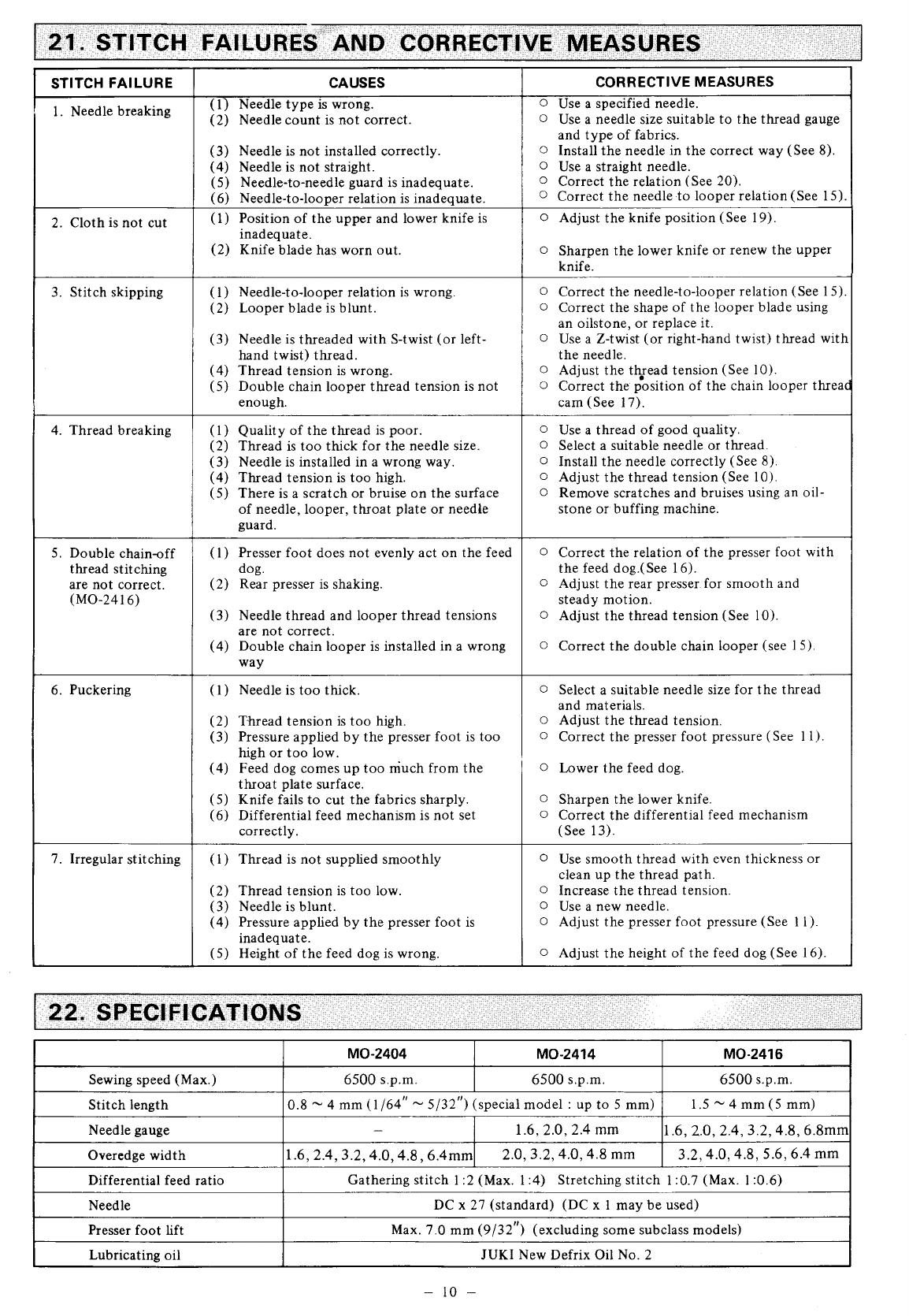
Juki MO-2414 Instruction book

Category
Sewing machines
Type
Instruction book

This manual is also suitable for

8E240430tsoA
No.04
MODEL
MO.24O4
l.NEEDLE
OVEREDGER
MODEL
MO-241
4
2.NEEDLE
OVEREDGER
MODEL
MO
-241
6
SAFETY
STITCHER
InsrnucTtoN
Congratulations on'
your
purchase
of JUKI
MO-2400
Series machines.
Please read this Instruction Book
carefully
before
using these units in order
to
get
the most out of
them and to enjoy using them for a long
time.
[For
ttre
first
one
month or
so, operate the
I
lmachine
at about
80% speed of its
max.
I
[sewing
speed.
J
BEFORE
OPERATION
Cloth
plate
cover
1. Do
not hold
the
cloth
plate
cover when
carrying
the
machine.
3.
Apply
two
or three
drops
of oil to
the needle bar
guide
and
upper
looper
guide
when
operating
the
machine for
the
first
time
after setup
or
after a long
period
of disuse.
A"iewed
from
toP)
oir
sause
sz
f&
2. lf
the
red color is'not
seen when
you
look down
or
sideward
at the
oil
gauge,
supply oil in
accordance with
"6.
Lubrication".
Running direction
4.
The
correct machine running direction
is
such that the handwheel
turns clock-
wise
as viewed
from
the handwheel's
side.
Never
run the machine in the
reverse
direction.
CAUTIONS IN
OPERATION
1.
Do
not
put
your
hand under the
needle
whijn
you
turn
on the
power
switch.
4. Never bring
your
fingers
or hair
close to, or
place
anything
on the
handwheel,
V-belt, bobbin
winder wheel or motor
during operation.
lt
may lead
to serious
personal
injuries.
5.
lf
your
machine is
provided
with a belt cover, finger
guard
and
eye
guard,
never operate
your
machine
with
any of
them removed.
2. Do not
put your
hand into the
face
plate
section
while
the
machine is
running.
3. Be sure
to turn
off the
power
switch before
you
remove the
V
belt.
-l-
*
Semi-sunken
type
8-o
e-
o
_e-
_o
I
Attach
blo*'er case
@ ,
rubber
cushion
@
.
rubber
cushion
seat
@
,
nut
€)
,
case
presser plate
@.
and case sponge
@
to frame
support
plate
Q
.
3.
Install upper
waste chute
@
to the
left on the table,
and then attach lower waste chute
@
to the upper
waste
chute.
The installation
of the
chutes can be adiusted
within
a
length
of 56 mm.
1. Attach
frame support
plate
joint
€),
blu.rr'e. case€).
ru-
bber cushronO.
rubber
cushion
seat
O.
case
presser
plate
@,
and case sp,,nge
@
to
frame
support
plate
(D.
*
Fully-sunken type
8-O
g-o
-o
3.
Attach waste
chute
@
to frame
support
plate
O
s
gg
os .,e
O
s
,tV)
V//
g
m
\.!./
9
gv
r.->:
-.4
e
c-l
(9
Table
I
2. Install frame
support
plate
O
directly
to the table
Install
frame support
plate
Q
so
that
the cloth
plate
is 5 mm higher
than
the
surface
of
the machine
table.
-2-
Sewing speed
(s.p.m.)
50
Hz
60
Hz
Motor
pulley
Outer
dia.
(mm)
V belt
(inch)
Motor
pulley
Outer
dia.
(mm)
(V
belt
(inch)
Semi-sunken
type
Fully-sunken
type
Semi-sunken
type
Fully-sunken
type
6500 r
20.5
38
32 t00.5
36
32
6000
110.s
36
32
95.5
35 30
5500
r
00.5
Jt)
)z
85.5
J5
30
s000
90.5
35
30
80.s
5.1
30
4500
85.s
35
30
70.5
34
30
Install
belt
cover
Q
to
the
machine head.
l Use
a
400W
(1/2
tP)
clutch
motor.
2.
UseaMtypeVbelt.
3. The
table on
the
left shows
the
sewing speeds obtained
by the
use of motor
pulleys
with
different diameters
and
V belts
with different lengths.
4. Note
that
the effective
dia-
meter
of
the
machine
head
pulley
has
been
changed
to
50
mm.
4.
INSTALLING
THE
PEDALS
l. Install
starting
pedal
Q
on
the left
and
presser
lifter
pedal
O
on
the
right
as seen from
the operator.
2.
Use an
S-shaped
hook
O
to
connect
the chain
@
of
the
presser
lifter
pedal
to
presser
lifting
lever
@
.
t
651t3"'NG
rHE BELr
5.
SETTING
UP THE
THREAD
STAND
Standard
thread
soool
Assemble
the
thread
stand
components
as illustrated
and
set
it
up on
the
machine table
(The
figure
on the
left shows
an
assembled
5-thread
stand
for
Model MO-2416.)
-3-
l.
2.
3.
Remove oil cap
()
.
Pour
JUKI New Defrix
Oil No.2
into
the oil reservoir.
Stop supplying
the oil
when
the red color has fully spread
as
you
look down at
oil
gauge
@
or when
the
red
color
has
reached the
red line
as
you
look
sidewards
at the oil
gauge.
Remove oil
drain cap
@
when
drawing the oil
reservou.
*
Lubricating
the
needle
color
l.
Open looper cover
O
,
tltt the needle
cooler
with
silicone oil through
6
,
using
the
furnished
oil
feeder.
2.
Infiltrate silicone orl
also
into the oil
fett
if the
machine
is
started
immediately after
lubricating
the
needle cooler.
7 .
OP
EN
I NG
/CLOS
I NG THE
COVER
*
Cloth
plate
cover
To open
cloth
plate
cover
O
,
push
down
cloth
plate
opening lever
O
To close the
cover,
push
it in the
arrowed
direction.
*
Looper
cover
To open
looper cover
@
,
move
the looper
cover in the arrowed
direction until
it will
go
back no
farther, then bring
it
down.
Raise
the looper cover when closing
it.
*
Chip
guard
cover(upper)
If the
chip
guard
cover
often interferes
with
the
upper looper. install chip
guarrl
covet'
upper
)
@.
(Caution)
For
a fully-sunken
table type,
make
sure to
lower waste chute opening
@
before opening
the looper
cover.
8.
ATTACHING
A NEEDLE
The
standard needle is DC
x 27
#1
1.
A
needle of
DC x
I can be also
used,
but it sometimes requires adjustment of the clearance
between
the looper
and needle.
It
is advisable
to use a needle of DC x2'7 for strict stitch
performance.
1. Bring needle clamp
O
to
the
highest
position.
2. Loosen needle clamp screw
@
,
and
fully
insert the
needle into the
needle clamp hole with the needle recess facing
backwards
as viewed from
the operator's side.
3. Tighten
the needle clamp
screw.
MO-2404 MO-24t
4 MO-24 |
6
-4-
9.
THREADING
THE MACHINE
Thread the
machine according to the threading chart
given
below.
(The
same chdrt
is on the inside
of the looper
cover.)
MO-2404
MO-24 |
6
MO-24t
4
Important
:
Lnri-z414:l
ffi:
(,trru+)
W/
Be
sure
to
pass
the double-chain stitch
needle
thread through the
needle
thread take-up.
(The
outer thread
is
the overlck
needle thread.)
(Gautionl
When using an untwisted thread
such
as wooly
nylon
thread or weak
thread,
do
not wind it round the intermediate
thread
guide.
-)-
I ntermediate
thread
guide
MO-2404
MO-2414
Using
the thread tension
nut, adjust
to an optimum
thread
tension according to
your
sewing conditions such as type
of materials,
type
and size of thread,
etc.
11.
PRESSER
FOOT
PRESSURE
AND LIFTER
MO-2404
Adjust
the
pressure
of
the
presser
foot by turning
presser
foot adjust
screw
O
.
When
the adjust screw
is
turned clockwise, the
pressure
increases,
while the
pressure
decreases when
the
screw is turned
counter-
clockwise.
When
you
turn
presser
foot assembly
O
side-ways,
bring
down
presser
lifting lever
@
.
Whenever the
presser
foot is returned
to
its
original
position,
be
sure to
bring
up
the
presser
lifting
lever.
MO-24 t4.MO-24tb
MO-24 t6
1.
Slowly
turn the handwheel
as
you
keep depressing
pushbutton
O
,
and
you
will
find
a
point
at which
the
pushbutton
goes
in
farther.
2.
With
the above condition
maintained,
align a desired
dial on
the
handwheel with
white mark
O
on the
belt cover.
3.
Reset
the
pushbutton
after
setting the
dial.
t t.
fro*r3f,IrNG
rHE
silrcH
MO-24
t6
13. DIFFERENTIAL
FEED
MECHANISM
l. Loosen differential
feed lock
nut
O
.
Turn lever O
up
for
stretching stitch
or
down
for
gathering
stitch.
2. Position "S" is
for stretching
stitch
of a ratio of l:0.7
and
position
"0"
provides
a
differential
feed rrtio of 1:1.
3.
Gathering
stitch
can
be made
up to a
differential
feed
ratio of
1:2
(possible
up to l:4
by adjusting
the
internal mechanism).
The divisions bevond
"0"
mav be used
as a measure.
-6-
When
the needle bar is
at the highest
point
of its stroke, the
pointed
end
of
the overedging
needle
should
be l0
mm above
the
throat olate surface.
MO-24
14
til|
]
(Stanoaro
teft
settins)
\/\/ I
MO-2404
10
mm
Throat
plate
Throat
plate
15.
SETTING
THE
LOOPERS
Go
back
farthest
*
Lower looper
l.
When lower
looper
Q
has
gone
back
farthest,
it
should
be distanced
3.7
to
4.3
mm from
overedging needle
O
.
2. When
the
lower looper
is
crossed with
the
needle,
the
clearance
between
them
should
be
0.05 to
0.1 mm.
3.
To
make
adjustment,
loosen
setscrew
O
and
move
lower
looper
holder
O
.
*
Upper looper
1. When
upper looper
@
has
advanced farthest,
it should be
distanced
10.4
to
11.0 mm
from
the
overedging
needle
for MO-2414,
and
10.7
to
1 1 .3
mm for
MO-2404
and
MO-2416.
2. The clearance
between
upper looper
O
and lower
looper
O
when
they are
crossed each
other should
be
0.05 to
0.2
mm.
3. To make
adjustment,
loosen
setscrew
@
and move
the
upper
looper.
*
Use a
proper
upper
looper
according
to the count
of
the
needle
used
in accordance
with
the table
shown
below. When
placing
orders,
specify
the bracketed
numbers[--l
.
Model
Numerals
engraved on
upper
looper
Count of Needle
1-Needle
Overedger
Safety
Stitcher
88@
#8
-
#13
(#14)
88m
#14
-
#20
(#13)
I
888
2-Needle Overedger
I
888
#6
-
#8
(#9\
88 l8al
#9- #16
*
Avoid using needles
with
the bracketed
counts as
much as
possible.
Go back
farthest
*
1
Double-chain
looper
0.05
-
0.1 mm
When double-chain
looper
O
has
gone
back
farthest,
it should
be distance l
8
to
2 mm from
double-chain needle
@
.
The clearance between the
double-chain
looper and needle
should be
0.05 to
0.1 mm when they
are crossed each other.
To
perform
the adjustment,
loosen set-
screw
(E
and
move double-chain looper
holder
O
.
2.
o
-4
It-
tl
\1
1J.t
lio
t/
-]._1.8-2mm
3mm
0.05
-
0.1
mm
--\-,
rl
\\\r-u
"lm\
ry/'
--\+r\\
\\\----o
"-A
ry
L
MO-2404
MO_2416
_
ru./
MO-2414
-
10.4
-
11.3 mm
-
11.0
mm
0.05
-
0.2
mm
-'7
-
0.8 mm
O.5 mm
I hroat
pl
ate
*
Height of
feed
dog
1. Feed dog
O
is usually
set so
that its teeth
protrude
about
0.8 mm
from
the throat
plate
surface at the highest
point
in
its trajectory. Increase the
protrusion
for
heavy-weight
materials
or reduce it for light-weight
materials.
2. Use setscrew
O
to adjust the
protrusion
of the feed dog
teeth.
3.
Using setscrew
O
,
make adjustment so
that
differential
feed dog
@
is level
with
the
main
feed
dog.
4.
Adjust the height of auxiliary feed
dog
O
by
setscrew
@
so that it is 0.5 mm lower
than the main
feed
doe.
*
Contact
of
the
presser
foot with
the throat
plate
top surface
Usirrg
adjust screw
@ ,
perform
adjustment so that
the sole of
the
presser
foot evenly comes in contact
with the top surface
of the throat
plate
when
presser
foot
O
comes down.
|?).*=il)1
*
Inclination
of feed dog
1. Loosen
screw
O
,
and
turn eccentric
shaft
O
in the
arrowed
direction
to make the feed
dog
front up
or turn it
in
the reverse
direction to set the feed
dog front down.
2.
The feed
dog should be levelled
when the dot
engraved
on
the
eccentric
shaft
faces
exactlv
to the ieft.
i
o
Front
up
1 7.
CHAIN LOOPER THREAD
CAM(MO-2416)
Loosen setscrew
@
,
and adjust
chain looper thread cam
O
so
that
6
of the chain
looper thread
cam
meets
the bottom of
looper thread
cam
pawl
O
when the needle
is
at
its highest
position.
Make sure that the
chain
looper thread
cam releases
the
looper thread
at the moment
the
needle
point
starts to
go
below
the bottom
of the
throat
plate
under
this condition.
. | |
Overedge
'"'""Kf*
Throat
plate
18.
THREAD
GUIDE
AND
LOOPER THREAD TAKE.UP
The
table below shows the
standard demensions of the individ-
ual thread
guides
and
looper thread take-ups when the upper
looper
has
gone
back farthest.
3ode
MO-2404
MO-2416
(Standard)
MO-2414
(Standard)
MO-2405
(Hemming
bottom)-
MO-2404
(Soft
chain)
G w
G
w G w
G
w
74 79.5
B
74
79
C
22.5
D
63
.5
E 40.5
F
26
C
37
.5
45 45 37 .5 45 4l 7
H
t2
IJ
18.5 9.5 t2 l3 26.5
6.5
24.5 33. 5 2E.0
33.5
J
23 I
K
L 74
M
63
l
-8-
G
: General
thread W
:
Wooly thread
(Unit
:
mm)
*
Height of the
lower
knife
Loosen
setscrew
€)
and
adjust the
height of lower
knife
O
so
that
its edge is
flush with the throat
plate
surface.
*
Height of the upper
knife
Loosen setscrews
O
,
O
and
perform
adjustment
so
that upper
knife
@
overlaps lower knife
O
by 0.5 to I mm
when the
upper
knife is at its lowert
point.
*
Overedge
width
Overedge
widths
of 1.6
thrqugh
6.4
mm are
provided
by
changing
the
parts
or
by using
subclass models.
(The
overedge
width will be
slightly larger than the knife cut
width.)
To change
the overedge widthl
l. Loosening
setscrew
@
,
push
lower
knife
O
to
the left
and
fix it.
2.
Loosen setscrew
@
and
move
upper knife
@
as
required,
then
fix it.
3.
Lower the upper knife to its lowest
point
and
loosen set-
screw
@
. Tighten
setscrew
@
when the lower knife comes
in contact with the upper knife.
(Caution)
Be
sure
to
tighten
screw
G)
before operating
machine.
*
Resharpening
the lower knife
When
the
lower knife
has become dull,
resharpen
it as
shown
in the
figure left.
20. NEEDLE GUARD
*
For
1-Needle
and 2-Needle Overedgers
An overedger is equipped with two
needle guards
O
and
O
.
1 . Position needle
guard
O
so that
it lightly comes in contact
with needle
O
when the blade
point
of
lower looper
O
has
reached the
center
of needle
O
.
2. Position
needle
guard
O
so that
it is 1
mm
lower than
the
bottom surface of
the throat
piate
end is distanced 0.1
mm
from needle
O
when the needle is at
its lowest
point.
*
For safety
stitchers
A safety stitcher has four
needle
guards
O
,
O
,
@
and
O
.
1. Position needle
guards
tl) and
O
in the
same manner
as the
overedger explained
above.
2.
Position needle
guard
O
so
that
it
lightly comes
in
contact
with needle
O
,
and
position
needle
guard
@
so that
it is
distanced
0.1 mm
from
needle@ when
the needle
is at its
iowest
point.
i
-9
-
STITCH
FAILURE CAUSES
CORRECTIVE
MEASURES
1. Needle
breaking
(l)
Needle type ls wrong.
(2)
Needle count is not
correct.
(3)
Needle is not installed correctly.
(4)
Needle is not straight.
(5)
Needle-to-needle
guard
is inadequate.
(6)
Needle-to-looper
relation is inadequate.
o
Use a
specified needle.
o
Use a needle size
suitable to the thread
gauge
and type of fabrics.
o
Install
the needle
in
the correct
way
(See
8).
o
Use a straight needle.
o
Correct
the relation
(See
20).
o
Correct
the needle
to looper relation(See 15).
2.
Cloth
is
not
cut
(
I
)
Position
of the upper and lower
knife is
inadequate.
(2)
Knife
blade
has worn
out.
o
Adjust
the knife
position
(
See
1
9).
o
Sharpen the lower
knife or
renew the
upper
knife.
3. Stitch skipping
(l)
(2)
(3)
(4)
(s)
Needle-to-looper
relation is
wrong.
Looper blade is blunt.
Needle is
threaded
with S-twist
(or
left-
hand twist) thread.
Thread
tension
is wrong.
Double
chain looper thread
tension is not
enough.
o
Correct the needle-toJooper
relation
(See
1 5).
o
Correct the shape of
the looper blade using
an oilstone, or replace
it.
o
Use a Z-twist
(or
right-hand
twist)
thread with
the needle.
o
Adjust the t\read tension
(See
l0).
o
Correct the
position
of
the chain
looper threac
cam
(See
l7).
4.
Thread
breaking
(
1)
Quality
of the thread
is
poor.
(2)
Thread
is too thick
for the needle size.
(3)
Needle is installed in a wrong way.
(4)
Thread
tension is too high.
(5)
There
is a
scratch or bruise on the surface
of needle, looper, throat
plate
or needle
suard.
o
Use a thread
of
good
quality.
o
Select a suitable needle or
thread.
o
Install the needle correctly
(See
8).
o
Adjust
the thread
tension
(See
10).
o
Remove
scratches and
bruises
using an oil-
stone or buffing machine.
5. Double
chain-off
thread stitching
are not correct.
(MO-2416)
(
I
)
Presser foot
does
not
evenly
act on the feed
dog.
(2)
Rear
presser
is
shaking.
(3)
Needle
thread and looper thread
tensions
are not correct.
(4)
Double
chain
looper
is installed
in
a
wrong
wav
o
Correct the relation of the
presser
foot with
the
feed dog.(See I 6).
o
Adjust
the rear
presser.
for
smooth
and
steady motion.
o
Adjust
the thread
tension
(See
l0).
o
Correct the double chain
looper
(see
I 5).
6. Puckering
(
I
)
Needle is
too
thick.
(2)
Tiread
tension
is too high.
(3)
Pressure
applied by the
presser
foot is too
high or too low.
(4)
Feed dog
comes
up too niuch
from
the
throat
plate
surface.
(5)
Knife fails to cut the
fabrics
sharply.
(6)
Differential feed mechanism is not set
correctly.
o
Select
a suitable
needle size for the thread
and materials.
Adjust
the thread
tension.
Correct
the
presser
foot
pressure
(See
I
1).
Lower
the
feed dog.
Sharpen the lower knife.
Correct
the
differential feed mechanism
(See
1 3).
o
o
o
o
o
Irregular
stitching
(
I
)
Thread is not
supplied
smoothly
(2)
Thread
tension
is too low.
(3)
Needle is
blunt.
(4)
Pressure applied by the
presser
foot is
inadequate.
(
5) Height of
the
feed dog is wrong.
Use smooth thread
with even thickness or
clean up the thread
path.
Increase
the thread
tension.
Use a new
needle.
Adjust the
presser
foot
pressure
(See
I l).
Adjust
the
height of the feed dog
(See
I 6)
o
o
o
22.
SPECIFICATIONS
MO-2404
MO-2414 MO-2416
Sewing speed
(Max.)
6500
s.p.m.
6500
s.p.m.
6500
s.p.m.
Stitch
length
0.8
-
4
mm(1
164"
-
5132")
(special
model
: up
to 5 mm)
1.5-4mm(5mm)
Needle
gauge
1.6,2.0,2.4
mm
1 .6,
2.0,
2.4,
3.2,4.8, 6.8mn
Overedge width
r.6,
2.4, 3.2, 4.O,4.8,
6.4mm
2.0.3.2.4.0.4.8
mm
3.2,
4.0,
4.8, 5.6, 6.4
mm
Differential feed
ratio
Gathering stitch
l:2
(Max.
l:4)
Stretching stitch
l:0.7
(Max.
l:0.6)
Needle
DC x 27
(standard) (DC
x I
may
be used)
Presser
foot lift
Max.
7.0 mm\9
132")
(excluding
some subclass models)
Lubricating
oil
JUKI
New
Defrix Oil
No.
2
-10-
(
iln:, l:,rl#'ii'fJT,ffi:i,:H $i:x't*ff
f:'
"
)
rl
I||llY||
JUlfi
Iil[U$In|l|.
80..[10.
I f
Head
Office &
Plant: 2-1,
8-chome,
Kokuryo-cho, Chofu-shi,
Tokyo, Japan
I I
Business Office: 23-3, Kabuki-cho
1-chome, Shiniuku-ku,
Tokyo 160, Japan
-
cabte: JUK| ToKYo
retex:22967:2g2-2301
Phone: 03(205)1
1
88,
1 189,
1 190
Appearance and specification listed
in
this catalog are
subjected to
change
without notice.
1981.'7
Printed
in Japan(11)
  • Page 1 1
  • Page 2 2
  • Page 3 3
  • Page 4 4
  • Page 5 5
  • Page 6 6
  • Page 7 7
  • Page 8 8
  • Page 9 9
  • Page 10 10
  • Page 11 11

Juki MO-2414 Instruction book

Category
Sewing machines
Type
Instruction book
This manual is also suitable for

Ask a question and I''ll find the answer in the document

Finding information in a document is now easier with AI