Subject to change without prior notice info@acs.com.hk
www.acs.com.hk
Reference Manual V1.01
ACR3901U-S1
Bluetooth
®
Contact Card Reader

ACR3901U-S1 – Reference Manual info@acs.com.hk
Version 1.01
www.acs.com.hk
Page 2 of 88
Table of Contents
1.0. Introduction ............................................................................................................. 5
1.1. Reference Documents ........................................................................................................... 5
1.2. Symbols and Abbreviations ................................................................................................... 5
2.0. Features ................................................................................................................... 6
3.0. Smart Card Support ................................................................................................ 7
3.1. MCU Cards ............................................................................................................................ 7
3.2. Memory-based Smart Cards.................................................................................................. 7
4.0. System Block Diagram ............................................................................................ 8
5.0. Hardware Design ..................................................................................................... 9
5.1. Battery .................................................................................................................................... 9
5.1.1. Battery charging ............................................................................................................ 9
5.1.2. Battery life ..................................................................................................................... 9
5.2. Bluetooth Interface ................................................................................................................. 9
5.3. USB Interface ........................................................................................................................ 9
5.3.1. Communication Parameters ......................................................................................... 9
5.3.2. Endpoints .................................................................................................................... 10
5.4. User Interface ...................................................................................................................... 10
5.4.1. Mode Selection Switch ................................................................................................ 10
5.4.2. Status LED .................................................................................................................. 10
5.5. Smart Card Interface ........................................................................................................... 11
5.5.1. Smart Card Power Supply VCC (C1) .......................................................................... 11
5.5.2. Programming Voltage VPP (C6) ................................................................................. 11
5.5.3. Card Type Selection.................................................................................................... 11
5.5.4. Interface for Microcontroller-based Cards................................................................... 12
5.5.5. Card Tearing Protection .............................................................................................. 12
6.0. Software Design .................................................................................................... 13
6.1. Bluetooth Connection Program Flow ................................................................................... 13
6.2. Profile Selection ................................................................................................................... 14
6.3. Authentication ...................................................................................................................... 16
6.4. Frame Format ...................................................................................................................... 19
6.4.1. Bluetooth Frame Format ............................................................................................. 19
6.4.2. Bluetooth Frame Format after Mutual Authentication ................................................. 19
6.5. Bluetooth Communication Protocol ..................................................................................... 20
6.5.1. Card Power On ........................................................................................................... 21
6.5.2. Card Power Off ........................................................................................................... 22
6.5.3. Get Card Presence ..................................................................................................... 23
6.5.4. APDU Command ......................................................................................................... 24
6.5.5. Escape Command....................................................................................................... 25
6.5.6. Customer Master Key Reset Request ........................................................................ 32
6.6. Mutual Authentication and Encryption Protocol ................................................................... 34
6.6.1. SPH_to_RDR_ReqAuth .............................................................................................. 35
6.6.2. RDR_to_SPH_AuthRsp1 ............................................................................................ 35
6.6.3. SPH_to_RDR_AuthRsp .............................................................................................. 36
6.6.4. RDR_to_SPH_AuthRsp2 ............................................................................................ 37
6.6.5. SPH_to_RDR_DataReq .............................................................................................. 37
6.6.6. RDR_to_SPH_DataRsp .............................................................................................. 38
7.0. USB Communication Protocol .............................................................................. 39
7.1. CCID Bulk-OUT Messages .................................................................................................. 41
7.1.1. PC_to_RDR_IccPowerOn ........................................................................................... 41
7.1.2. PC_to_RDR_IccPowerOff ........................................................................................... 41
7.1.3. PC_to_RDR_GetSlotStatus ........................................................................................ 41

ACR3901U-S1 – Reference Manual info@acs.com.hk
Version 1.01
www.acs.com.hk
Page 3 of 88
7.1.4. PC_to_RDR_XfrBlock ................................................................................................. 42
7.1.5. PC_to_RDR_GetParameters ...................................................................................... 42
7.1.6. PC_to_RDR_ResetParameters .................................................................................. 42
7.1.7. PC_to_RDR_SetParameters ...................................................................................... 43
7.2. CCID Bulk-IN Messages ...................................................................................................... 45
7.2.1. RDR_to_PC_DataBlock .............................................................................................. 45
7.2.2. RDR_to_PC_SlotStatus .............................................................................................. 45
7.2.3. RDR_to_PC_Parameters ............................................................................................ 46
8.0. Memory Card Command Set ................................................................................. 47
8.1. Memory Card – 1, 2, 4, 8, and 16 kilobit I2C Card .............................................................. 47
8.1.1. SELECT_CARD_TYPE .............................................................................................. 47
8.2. Memory Card – 32, 64, 128, 256, 512, and 1024 kilobit I2C Card ...................................... 50
8.2.1. SELECT_CARD_TYPE .............................................................................................. 50
8.2.2. SELECT_PAGE_SIZE ................................................................................................ 50
8.2.3. READ_MEMORY_CARD ............................................................................................ 51
8.2.4. WRITE_MEMORY_CARD .......................................................................................... 51
8.3. Memory Card – ATMEL AT88SC153 .................................................................................. 53
8.3.1. SELECT_CARD_TYPE .............................................................................................. 53
8.3.2. READ_MEMORY_CARD ............................................................................................ 53
8.3.3. WRITE_MEMORY_CARD .......................................................................................... 54
8.3.4. VERIFY_PASSWORD ................................................................................................ 55
8.3.5. INITIALIZE_AUTHENTICATION ................................................................................. 55
8.3.6. VERIFY_AUTHENTICATION ..................................................................................... 56
8.4. Memory Card – ATMEL AT88C1608 ................................................................................... 57
8.4.1. SELECT_CARD_TYPE .............................................................................................. 57
8.4.2. READ_MEMORY_CARD ............................................................................................ 57
8.4.3. WRITE_MEMORY_CARD .......................................................................................... 58
8.4.4. VERIFY_PASSWORD ................................................................................................ 59
8.4.5. INITIALIZE_AUTHENTICATION ................................................................................. 59
8.4.6. VERIFY_AUTHENTICATION ..................................................................................... 60
8.5. Memory Card – SLE4418/SLE4428/SLE5518/SLE5528 .................................................... 61
8.5.1. SELECT_CARD_TYPE .............................................................................................. 61
8.5.2. READ_MEMORY_CARD ............................................................................................ 61
8.5.3. READ_PRESENTATION_ERROR_COUNTER_MEMORY_CARD (SLE4428 and
SLE5528) 62
8.5.4. READ_PROTECTION_BIT ......................................................................................... 62
8.5.5. WRITE_MEMORY_CARD .......................................................................................... 63
8.5.6. WRITE_PROTECTION_MEMORY_CARD ................................................................ 64
8.5.7. PRESENT_CODE_MEMORY_CARD (SLE4428 and SLE5528) ............................... 64
8.6. Memory Card – SLE4432/SLE4442/SLE5532/SLE5542 .................................................... 66
8.6.1. SELECT_CARD_TYPE .............................................................................................. 66
8.6.2. READ_MEMORY_CARD ............................................................................................ 66
8.6.3. READ_PRESENTATION_ERROR_COUNTER_MEMORY_CARD (SLE 4442 and
SLE 5542) 67
8.6.4. READ_PROTECTION_BITS ...................................................................................... 67
8.6.5. WRITE_MEMORY_CARD .......................................................................................... 68
8.6.6. WRITE_PROTECTION_MEMORY_CARD ................................................................ 68
8.6.7. PRESENT_CODE_MEMORY_CARD (SLE 4442 and SLE 5542) ............................. 69
8.6.8. CHANGE_CODE_MEMORY_CARD (SLE 4442 and SLE 5542) .............................. 70
8.7. Memory Card – SLE 4406/SLE 4436/SLE 5536/SLE 6636 ................................................ 71
8.7.1. SELECT_CARD_TYPE .............................................................................................. 71
8.7.2. READ_MEMORY_CARD ............................................................................................ 71
8.7.3. WRITE_ONE_BYTE_MEMORY_CARD ..................................................................... 72
8.7.4. PRESENT_CODE_MEMORY_CARD ........................................................................ 73
8.7.5. AUTHENTICATE_MEMORY_CARD (SLE 4436, SLE 5536 and SLE 6636) ............. 74
8.8. Memory Card – SLE 4404 ................................................................................................... 76
8.8.1. SELECT_CARD_TYPE .............................................................................................. 76
8.8.2. READ_MEMORY_CARD ............................................................................................ 76
8.8.3. WRITE_MEMORY_CARD .......................................................................................... 77

ACR3901U-S1 – Reference Manual info@acs.com.hk
Version 1.01
www.acs.com.hk
Page 4 of 88
8.8.4. ERASE_SCRATCH_PAD_MEMORY_CARD ............................................................ 77
8.8.5. VERIFY_USER_CODE ............................................................................................... 78
8.8.6. VERIFY_MEMORY_CODE ........................................................................................ 79
8.9. Memory Card – AT88SC101/AT88SC102/AT88SC1003 .................................................... 80
8.9.1. SELECT_CARD_TYPE .............................................................................................. 80
8.9.2. READ_MEMORY_CARD ............................................................................................ 80
8.9.3. WRITE_MEMORY_CARD .......................................................................................... 81
8.9.4. ERASE_NON_APPLICATION_ZONE ........................................................................ 81
8.9.5. ERASE_APPLICATION_ZONE_WITH_ERASE ........................................................ 82
8.9.6. ERASE_APPLICATION_ZONE_WITH_WRITE_AND_ERASE ................................. 83
8.9.7. VERIFY_SECURITY_CODE ...................................................................................... 84
8.9.8. BLOWN_FUSE ........................................................................................................... 85
9.0. Other Commands Access via PC_to_RDR_XfrBlock .......................................... 86
9.1. GET_READER_INFORMATION ......................................................................................... 86
List of Figures
Figure 1 : ACR3901U-S1 Architecture ................................................................................................... 8
Figure 2 : Bluetooth Connection Flow .................................................................................................. 13
Figure 3 : nRFgo Studio GATT Setting Interface ................................................................................. 14
Figure 4 : Authentication Procedure ..................................................................................................... 17
List of Tables
Table 1 : Symbols and Abbreviations ..................................................................................................... 5
Table 2 : Estimated Battery Lifespan ...................................................................................................... 9
Table 3 : USB Interface Wiring ............................................................................................................... 9
Table 4 : Mode Selection Switch .......................................................................................................... 10
Table 5 : Status LED ............................................................................................................................. 11
Table 6 : ACR3901U-S1 Service Handles and UUID Information List ................................................. 15
Table 7 : Bluetooth Frame Format ........................................................................................................ 19
Table 8 : Encrypted Frame Format after Mutual Authentication ........................................................... 19
Table 9 : Command Code Summary .................................................................................................... 20
Table 10 : Response Code Summary .................................................................................................. 20
Table 11 : Supported Card Types ........................................................................................................ 87
Table 12 : Error Code ........................................................................................................................... 88

ACR3901U-S1 – Reference Manual info@acs.com.hk
Version 1.01
www.acs.com.hk
Page 5 of 88
1.0. Introduction
ACR3901U-S1 Bluetooth Contact Card Reader acts as an interface for the communication between a
computer/mobile device and a smart card. Different types of smart cards have different commands
and different communication protocols which, in most cases, prevent direct communication between a
smart card and a computer/mobile device. ACR3901U-S1 Bluetooth Contact Card Reader establishes
a uniform interface from the computer/mobile device to the smart card for a wide variety of cards. By
taking care of the card’s particulars, it releases the computer software programmer from being
responsible with smart card operations’ technical details, which in many cases, are not relevant to the
implementation of a smart card system.
1.1. Reference Documents
The following related documents are available from www.usb.org
• Universal Serial Bus Specification 2.0 (also referred to as the USB specification), April 27,
2000
• Universal Serial Bus Common Class Specification 1.0, December 16, 1997
• Universal Serial Bus Device Class: Smart Card CCID Specification for Integrated Circuit(s)
Cards Interface Devices, Revision 1.1, April 22, 2005
The following related documents can be ordered through www.ansi.org
• ISO/IEC 7816-1; Identification Cards – Integrated circuit(s) cards with contacts - Part 1:
Physical Characteristics
• ISO/IEC 7816-2; Identification Cards – Integrated circuit(s) cards with contacts - Part 2:
Dimensions and Locations of the contacts
• ISO/IEC 7816-3; Identification Cards – Integrated circuit(s) cards with contacts - Part 3:
Electronic signals and transmission protocols
1.2. Symbols and Abbreviations
Abbreviation Description
ATR Answer-To-Reset
CCID Chip/Smart Card Interface Device
ICC Integrated Circuit Cards
IFSC Information Field Sized for ICC for protocol T=1
IFSD Information Field Sized for CCID for protocol T=1
NAD Node Address
PPS Protocol and Parameters Selection
RFU Reserved for future use
1
TPDU Transport Protocol Data Unit
USB Universal Serial Bus
Table 1: Symbols and Abbreviations
1
Must be set to zero unless stated differently.

ACR3901U-S1 – Reference Manual info@acs.com.hk
Version 1.01
www.acs.com.hk
Page 6 of 88
2.0. Features
• USB 2.0 Full Speed Interface
• Bluetooth® Smart Interface
• Plug and Play – CCID support brings utmost mobility
• USB Firmware Upgradeability
2
• Smart Card Reader:
o Supports ISO 7816 Class A, B and C (5 V, 3 V, 1.8 V) cards
o Supports microprocessor cards with T=0 or T=1 protocol
o Supports memory cards
o Supports PPS (Protocol and Parameters Selection)
o Features Short Circuit Protection
o Supports AES-128 encryption algorithm
• Application Programming Interface:
o Supports PC/SC
o Supports CT-API (through wrapper on top of PC/SC)
• Supports Android™ 4.3 and above
3
• Supports iOS 5.0 and above
4
• Built-in Peripherals:
o LEDs
• Compliant with the following standards:
o EN60950/IEC 60950
o ISO 7816
o CE
o FCC
o VCCI
o PC/SC
o CCID
o EMV™ 2000 Level 1
o Bluetooth® Smart
o Microsoft
® WHQL
o RoHS 2
o REACH
2
Applicable under PC-linked mode
3
PC/SC and CCID support are not applicable
4
Same as above

ACR3901U-S1 – Reference Manual info@acs.com.hk
Version 1.01
www.acs.com.hk
Page 7 of 88
3.0. Smart Card Support
3.1. MCU Cards
ACR3901U-S1 is a PC/SC compliant smart card reader that supports ISO 7816 Class A, B and C (5
V, 3 V, and 1.8 V) smart cards. It also works with MCU cards following either the T=0 and T=1
protocol.
The card ATR indicates the specific operation mode (TA2 present; bit 5 of TA2 must be 0) and when
that particular mode is not supported by the ACR3901U-S1, it will reset the card to negotiable mode. If
the card cannot be set to negotiable mode, the reader will then reject the card.
When the card ATR indicates the negotiable mode (TA2 not present) and communication parameters
other than the default parameters, the ACR3901U-S1 will execute the PPS and try to use the
communication parameters that the card suggested in its ATR. If the card does not accept the PPS,
the reader will use the default parameters (F=372, D=1).
For the meaning of the aforementioned parameters, please refer to ISO 7816-3.
3.2. Memory-based Smart Cards
ACR3901U-S1 works with several memory-based smart cards such as:
• Cards following the I2C bus protocol (free memory cards) with maximum 128 bytes page with
capability, including:
o Atmel®: AT24C01/02/04/08/16/32/64/128/256/512/1024
o SGS-Thomson: ST14C02C, ST14C04C
o Gemplus: GFM1K, GFM2K, GFM4K, GFM8K
• Cards with secure memory IC with password and authentication, including:
o Atmel®: AT88SC153 and AT88SC1608
• Cards with intelligent 1 KB EEPROM with write-protect function, including:
o Infineon®: SLE4418, SLE4428, SLE5518 and SLE5528
• Cards with intelligent 256 bytes EEPROM with write-protect function, including:
o Infineon®: SLE4432, SLE4442, SLE5532 and SLE5542
• Cards with ‘104’ type EEPROM non-reloadable token counter cards, including:
o Infineon®: SLE4406, SLE4436, SLE5536 and SLE6636
• Cards with Intelligent 416-bit EEPROM with internal PIN check, including:
o Infineon®: SLE4404
• Cards with Security Logic with Application Zone(s), including:
o Atmel®: AT88SC101, AT88SC102 and AT88SC1003

ACR3901U-S1 – Reference Manual info@acs.com.hk
Version 1.01
www.acs.com.hk
Page 8 of 88
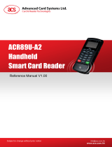
4.0. System Block Diagram
Figure 1: ACR3901U-S1 Architecture
ACR3901U-S1
Power
Management
MCU
Bluetooth
Mobile device or
Computer
LEDs
Full-sized
Card
Re-chargeable
battery
Bluetooth module
USB
Computer

ACR3901U-S1 – Reference Manual info@acs.com.hk
Version 1.01
www.acs.com.hk
Page 9 of 88
5.0. Hardware Design
5.1. Battery
ACR3901U-S1 is using a rechargeable Lithium-ion battery which has a capacity of 320 mAh.
5.1.1. Battery charging
Once the battery of ACR3901U-S1 runs out, it may be charged in any of the following modes: OFF,
USB, Bluetooth; as long as it is connected to a power outlet.
5.1.2. Battery life
The battery life is dependent on the usage of the device. Below is an estimate of the battery life
depending on the various work conditions:
Mode Estimated Battery Life
Working Mode 10 hours*
Standby Mode 7 days
OFF Mode 8 years
Table 2: Estimated Battery Lifespan
*Note: Results may vary as it depends on the smart card used.
5.2. Bluetooth Interface
ACR3901U-S1 uses Bluetooth Low Energy (LE) 4.0 as the medium to pair the device with
computers/mobile devices.
5.3. USB Interface
The Micro USB port is used to connect the ACR3901U-S1 to the computer as battery charging port.
This port is also used in order for the ACR3901U-S1 to operate in PC-linked mode.
5.3.1. Communication Parameters
ACR3901U-S1 is connected to a computer through USB as specified in the USB Specification 2.0.
ACR3901U-S1 is working in full speed mode, i.e. 12 Mbps.
Pin Signal Function
1 V
BUS
+5 V power supply for the reader
2 D- Differential signal transmits data between ACR3901U-S1 and PC
3 D+ Differential signal transmits data between ACR3901U-S1 and PC
4 GND Reference voltage level for power supply
Table 3: USB Interface Wiring

ACR3901U-S1 – Reference Manual info@acs.com.hk
Version 1.01
www.acs.com.hk
Page 10 of 88
5.3.2. Endpoints
ACR3901U-S1 uses the following endpoints to communicate with the host computer:
Control Endpoint
For setup and control purpose
Bulk OUT
For command to be sent from host to ACR3901U-S1
(data packet size is 64 bytes)
Bulk IN
For response to be sent from ACR3901U-S1 to host
(data packet size is 64 bytes)
Interrupt IN
For card status message to send from ACR3901U-S1 to host
(data packet size is 8 bytes)
5.4. User Interface
5.4.1. Mode Selection Switch
ACR3901U-S1 has three modes: USB, Off and Bluetooth. User can select one mode at a time as a
data transmission interface.
Symbol Switch Active Mode
USB PC-linked
Off No power
Bluetooth Bluetooth
Table 4: Mode Selection Switch
5.4.2. Status LED
ACR3901U-S1 has three LEDs to show the various operation status, where:
• Red LED - Battery status
• Blue LED - Bluetooth status
• Green LED - Card and reader status
Color LED Activity Status
Red
Off
• The battery is fully charged
• The reader is powered off
• The voltage of the battery is greater than 2.8 V and
no USB powered is being supplied
On
• The battery is charging
Slow flash
(1 second/flash)
• The battery needs to be charged
Blue Off
• The reader is powered off
• There is no Bluetooth device paired, or being paired
• The reader is in USB mode

ACR3901U-S1 – Reference Manual info@acs.com.hk
Version 1.01
www.acs.com.hk
Page 11 of 88
Color LED Activity Status
Slow flash
(2 seconds/flash)
• There is a Bluetooth device paired and:
o The reader is waiting for instructions, or
o No card is present, or
o
The card is powered off
Fast flash
• Data is being transferred between the reader and
paired device
Fast – Slow flash
(Fast: 250 ms/flash;
Slow: 500 ms/flash)
• Bluetooth disconnected
• Ready for pairing
On
• Bluetooth device is paired with the reader
• The card is powered on
Green
Off
• The reader is powered off
Slow flash
(2 seconds/flash)
• There is no card operation and the reader is waiting
for instruction
Fast blink
• There is read/write access between the smart card
and reader
On
• The card is connected and powered on
Table 5: Status LED
Note: Both blue and green LEDs will light for 1 second, then turn off when the reader received some
critical error codes from the Bluetooth module.
5.5. Smart Card Interface
The interface between the ACR3901U-S1 and the inserted smart card follows the specification of ISO
7816-3 with certain restrictions or enhancements to increase the practical functionality of ACR3901U-
S1.
5.5.1. Smart Card Power Supply VCC (C1)
The current consumption of the inserted card must not be higher than 50 mA.
5.5.2. Programming Voltage VPP (C6)
According to ISO 7816-3, the smart card contact C6 (VPP) supplies the programming voltage to the
smart card. Since all common smart cards in the market are EEPROM-based and do not require the
provision of an external programming voltage, the contact C6 (VPP) has been implemented as a
normal control signal in the ACR3901U-S1. The electrical specifications of this contact are identical to
those of the signal RST (at contact C2).
5.5.3. Card Type Selection
The controlling computer must always select the card type through the proper command sent to the
ACR3901U-S1 prior to activating the inserted card. This includes both the memory cards and MCU-
based cards.
For MCU-based cards, the reader allows to select the preferred protocol, T=0 or T=1. However, this
selection is only accepted and carried out by the reader through the PPS when the card inserted in
the reader supports both protocol types. Whenever an MCU-based card supports only one protocol
type, T=0 or T=1, the reader automatically uses that protocol type, regardless of the protocol type
selected by the application.

ACR3901U-S1 – Reference Manual info@acs.com.hk
Version 1.01
www.acs.com.hk
Page 12 of 88
5.5.4. Interface for Microcontroller-based Cards
For microcontroller-based smart cards, only the contacts C1 (VCC), C2 (RST), C3 (CLK), C5 (GND)
and C7 (I/O) are used. A frequency of 4.8 MHz is applied to the CLK signal (C3).
5.5.5. Card Tearing Protection
The ACR3901U-S1 provides a mechanism to protect the inserted card when it is suddenly withdrawn
while it is powered up. The power supply to the card and the signal lines between theACR3901U-S1
and the card is immediately deactivated when the card is being removed. However, as a rule to avoid
any electrical damage, a card should only be removed from the reader while it is powered down.
Note: ACR3901U-S1 never switches on the power supply to the inserted card by itself. The
controlling computer through the proper command sent to the reader must explicitly do this.

ACR3901U-S1 – Reference Manual info@acs.com.hk
Version 1.01
www.acs.com.hk
Page 13 of 88
6.0. Software Design
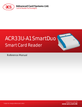
6.1. Bluetooth Connection Program Flow
The program flow of a Bluetooth connection is shown below:
Figure 2: Bluetooth Connection Flow
Yes
No
Bluetooth Start
(Reset/Power up)
Connect Success?
No
Enable Service
Disconnect?
Reset
Power Off
Authentication
Smart card operation with security channel
Authenticate Success?
Yes

ACR3901U-S1 – Reference Manual info@acs.com.hk
Version 1.01
www.acs.com.hk
Page 14 of 88
6.2. Profile Selection
ACR3901U-S1 is a smart card reader that is designed to use Bluetooth technology as an interface to
transmit data. A customized service called Commands Communication with three pipes is used: one
pipe is used for command request, second pipe is for command response, and the third pipe is used
to notify the paired device about the card and sleep mode status.
Also, the current reader’s battery status is significant when the reader is operating in Bluetooth mode,
hence, a customized Battery service is used to notify the paired device about the current battery
status. When there is a change in the battery status, the reader will notify the paired device through a
specific pipe.
Also, the current reader’s battery status is significant when the reader is operating in Bluetooth mode,
hence, a customized Battery service is used to notify the paired device about the current battery
status. When there is a change in the battery status, the reader will notify the paired device through a
specific pipe. To simplify, the battery levels are divided into three groups, below is a table
summarizing the battery level and its corresponding return value:
Status Voltage Return Value
Sufficient battery ≥ 3.3 V FEh
Low battery <3.1 V and ≥ 2.9 V Value other than FFh/FEh/00h
No battery <2.9 V 00h
USB mode FFh
In Card Status Notification service, it will notify the paired device on any changes on the card status or
when the reader enters sleep mode. Below is a list of the status and the corresponding return value:
Status Return Value
No card present 50 02h
Card present 50 03h
Reader has entered sleep mode 50 04h
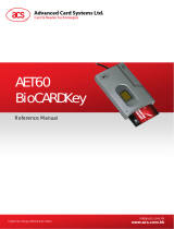
Finally, to provide more reader information to the user, a customized Device Information service was
added. This can only be read manually, or by an application request. The characteristics include
Manufacturer Name, Firmware Revision, Model Number, and Serial Number.
Figure 3: nRFgo Studio GATT Setting Interface

ACR3901U-S1 – Reference Manual info@acs.com.hk
Version 1.01
www.acs.com.hk
Page 15 of 88
nRFgo-Studio Configuration adds one service, and there will be totally 10 services:
#define PIPE_GAP_DEVICE_NAME_SET 1
#define PIPE_COMMANDS_COMMUNICATION_COMMANDS_RESPONSE_TX 2
#define PIPE_COMMANDS_COMMUNICATION_COMMANDS_REQUEST_RX 3
#define PIPE_COMMANDS_COMMUNICATION_CARD_STATUS_NOTIFICATION_TX 4
#define PIPE_BATTERY_BATTERY_LEVEL_TX 5
#define PIPE_BATTERY_BATTERY_LEVEL_SET 6
#define PIPE_DEVICE_INFORMATION_MANUFACTURER_NAME_STRING_SET 7
#define PIPE_DEVICE_INFORMATION_FIRMWARE_REVISION_STRING_SET 8
#define PIPE_DEVICE_INFORMATION_MODEL_NUMBER_STRING_SET 9
#define PIPE_DEVICE_INFORMATION_SERIAL_NUMBER_STRING_SET 10
#define NUMBER_OF_PIPES 10
#define PIPE_GAP_DEVICE_NAME_SET is used to change the device name at runtime by the
application controller. So that in Bluetooth mode, the advertising name will be in the format of
“ACR3901U-S1XXXXXXX”, where “XXXXXXX” is the last 7 bytes of reader’s serial number.
In order to make the advertising name be “ACR3901U-S1XXXXXXX”, Bluetooth Mode Start operation
should be implemented first.
Bluetooth Mode Start:
1. Setup (06h) uploads the configuration to Bluetooth module.
2. Use pipe 1 to set the device name in the format of “ACR3901U-S1XXXXXXX”
(PIPE_GAP_DEVICE_NAME_SET)
3. Connect (0Fh).
4. Advertising.
Attribute Name UUID Handle
DeviceName 2A00 03h
Send (Reader → Paired device)
8002 0Bh
Receive
(Paired device →Reader)
8003 0Eh
CardStatus 8004 10h
BatteryLevel 2A19 14h
Manufacturer 2A29 18h
FW_Version 2A26 1Bh
ModelNumber 2A24 1Eh
SerialNumber 2A25 21h
Table 6: ACR3901U-S1 Service Handles and UUID Information List

ACR3901U-S1 – Reference Manual info@acs.com.hk
Version 1.01
www.acs.com.hk
Page 16 of 88
6.3. Authentication
Before any sensitive data can be loaded into ACR3901U-S1, the data processing server must be
authenticated by ACR3901U-S1 for the privilege to modify the secured data inside reader. In
ACR3901U-S1, a mutual authentication method is being used.
An authentication request is always initiated by either the data processing server or the bridging
device, which will then trigger ACR3901U-S1 to return a sequence of 16 bytes of random numbers
(RND_A[0:15]). The random numbers are encrypted with the Customer Master Key currently stored in
ACR3901U-S1 using the AES-128 CBC ciphering mode before being sent out from ACR3901U-S1.
The bridging device must pass this sequence of encrypted random numbers to the data processing
server, which will then undergo AES-128 CBC cipher mode decryption using the Customer Master
Key that is being used in the data processing server (which should be the same as the one that is
being used in ACR3901U-S1 and should be kept securely by the customer). The 16 bytes of
decrypted random numbers from ACR3901U-S1 is then padded to the end of another 16 bytes of
random numbers generated by the data processing server (RND_B[0:15]). The final sequence of 32
bytes of random numbers (RND_C[0:31]), that is:
RND_C[0:31] = RND_B[0:15] + RND_A[0:15],
will undergo decryption operation with the Customer Master Key being used in the server and the final
output data is sent to ACR3901U-S1 through the bridging device using an authentication response
message.
When ACR3901U-S1 receives the authentication response message, the message data will undergo
a decryption operation using its own Customer Master Key and will be converted back to the normal
32 bytes of random numbers. In theory, the first 16 bytes of random numbers should be equal to
RND_B[0:15] and are generated by the data processing server while the other 16 bytes should be
equal to RND_A[0:15] and are originally generated by ACR3901U-S1.
ACR3901U-S1 will first compare if RND_A[0:15] is the same as the original version. If it is the same,
then the data processing server is authenticated by ACR3901U-S1. ACR3901U-S1 will then encrypt
RND_B[0:15] obtained using the Customer Master Key and the feedback to the data processing
server through the bridging device using the answer to the authentication response message.
Upon receiving the answer to the authentication response message, the data processing server will
decrypt the data contained in the message and check if the 16 bytes of random numbers are all equal
to those originally generated RND_B[0:15]. If they are the same, then ACR3901U-S1 is authenticated
by the server. At this moment, the whole authentication process is completed and sensitive data can
be injected into ACR3901U-S1.
After successful authentication, a 16-byte Session Key is generated in both ACR3901U-S1 and the
data processing server. The Session Key (SK[0:15]) is obtained by padding the first 8 bytes of RND_A
at the end of the first 8 bytes of RND_B, that is:
SK[0:15] = RND_B[0:7] + RND_A[0:7]
All sensitive data leaving out of the Secured Data Processing Server must be encrypted with this
Session Key using the AES-128 CBC ciphering mode. Thus, even if the encrypted data may be
captured in the bridging mobile device, it is still very difficult to retrieve the original sensitive data
without any prior knowledge of the Customer Master Key.
The reader will refuse any authentication request if the authentication failed more than 5 times,
continuously. A master reset is needed to reset the reader.

ACR3901U-S1 – Reference Manual info@acs.com.hk
Version 1.01
www.acs.com.hk
Page 17 of 88
For better pictorial illustration, please refer to figure below (The picture below has omitted the bridging
device for simplicity and better illustration):
Figure 4: Authentication Procedure
Below is a summary of the above mentioned steps:
1. The data processing server/bridging device initiates an authentication request from
ACR3901U-S1 by issuing an authentication request message.
2. Upon receiving the authentication request message, ACR3901U-S1 will generate 16 bytes of
random numbers (RND_A[0:15]). The whole 16 bytes of data is encrypted with the Customer
Master Key currently being used by ACR3901U-S1.
3. The encrypted version of RND_A[0:15] is then transferred to the data processing server
through the answer to the authentication response message.
4. The data processing server will decrypt the data received to recover RND_A[0:15].
5. The data processing server will generate another 16 bytes of random numbers (RND_B[0:15]).
RND_A[0:15] will be padded to the end of RND_B[0:15] to form a sequence of 32-byte
random numbers (RND_C[0:31] = RND_B[0:15] + RND_A[0:15]). All the 32 bytes of random
numbers will undergo a decryption process with the Customer Master Key currently being
used in the server.
6. The final output data from the encryption process will be transferred to ACR3901U-S1
through the authentication response message.
7. In ACR3901U-S1, a decryption process will be performed on the received data to recover the
32 bytes of random number. ACR3901U-S1 will check the result RND_A[0:15] to see if they
are the same as the original ones. If not, the authentication process will be terminated.
8. ACR3901U-S1 will encrypt the resultant RND_B[0:15] with the Customer Master Key. At the
same time, a 16-byte Session Key is created by padding the first 8 bytes of RND_A to the end
of the first 8 bytes of RND_B.
1.
Send authentication
request message
3.
Answer to the request
message
2
6.
Send authentication
response message
7
8
9.
Answer to the
authentication response
message
4
5
10
Transmitted
through the
bridging device

ACR3901U-S1 – Reference Manual info@acs.com.hk
Version 1.01
www.acs.com.hk
Page 18 of 88
9. The encrypted RND_B[0:15] will be transferred to the data processing server through the
authentication response message.
10. The data processing server will decrypt the message data and compare if the content is equal
to the original RND_B[0:15]. If not, the authentication process will be terminated. Otherwise,
the authentication process is completed and a 16-byte Session Key is created by padding the
first 8 bytes of RND_A to the end of the first 8 bytes of RND_B.

ACR3901U-S1 – Reference Manual info@acs.com.hk
Version 1.01
www.acs.com.hk
Page 19 of 88
6.4. Frame Format
6.4.1. Bluetooth Frame Format
HID Frame Length (Bytes) Description
Identifiers 1 Commands
Length 2 Length {Payload+Checksum}
Payload 0-N Data
Checksum 1 XOR {Identifiers,Length,Payload}
Table 7: Bluetooth Frame Format
The frame format should be:
Identifier + LEN1 + LEN2 + N-bytes Payload + Checksum
If the total command length, including identifier, length, and payload, is greater than 20 bytes, then the
reader or the paired device will automatically divide it into several frames.
Data checksum is used in detecting errors that may have been introduced during wireless data
transmission. To calculate the data checksum: XOR {Identifiers,Length,Payload}.
Example: 62010063 => Checksum = 63h
6.4.2. Bluetooth Frame Format after Mutual Authentication
Mutual authentication was introduced to avoid man in the middle attack through the Bluetooth
communication channel. After a successful mutual authentication, the Bluetooth Frame Format in
Table 7 will be encrypted and packed with 1 byte header byte, 2 Len byte, and 1 check byte. The
frame format after mutual authentication should look like the structure below:
Header + Len + (Identifiers + Length + Payload + Checksum)* + Check byte
Note: Each 16 bytes of data will be decrypted with the Customer Master Key using the AES-128
CBC cipher mode. The initial vector is 16 bytes (00h) in AES-128 CBC cipher mode.
HID Frame Length (Bytes) Description
Header byte 1 Value: 72h / 22h
Len 2
Length {Identifiers + Length + Payload + Checksum +
Check + Stop byte}
Identifiers 1 Commands
Encrypted data of
the Bluetooth frame
format;
The final data length
of this part is 16*N
bytes (N>0)
Length 2 Length {Payload + Checksum}
Payload 0-N Data
Checksum 1 XOR {Identifiers, Length, Payload}
Check byte 1
XOR {Header, Len, Encrypted(Identifiers, Length, Payload,
Checksum)}
Table 8: Encrypted Frame Format after Mutual Authentication

ACR3901U-S1 – Reference Manual info@acs.com.hk
Version 1.01
www.acs.com.hk
Page 20 of 88
6.5. Bluetooth Communication Protocol
ACR3901U-S1 communicates to the paired device using the Bluetooth interface with a predefined
protocol. The protocol is similar to the formats of the CCID Command Pipe and Response Pipe.
Command Mode supported Sender Description
62h Authenticated Paired device ICC Power On
63h Authenticated Paired device ICC Power Off
65h Authenticated Paired device Get Card Presence
6Fh Authenticated Paired device Exchange APDU
6Bh Authenticated Paired device Peripheral Commands
70h Connected/Authenticated Paired device SPH_to_RDR_ReqAuth*
71h Connected/Authenticated Paired device SPH_to_RDR_AuthRsp*
Table 9: Command Code Summary
Command Mode Supported Sender Description
12h Authenticated Reader Response to ICC Power On
14h Authenticated Reader Response to Get Card Presence
11h Authenticated Reader Response to Exchange APDU
13h Authenticated Reader Response to ICC Power Off
15h Authenticated Reader Response to Peripheral Commands
20h Connected/Authenticated Reader RDR_to_SPH_AuthRsp1*
21h Connected/Authenticated Reader RDR_to_SPH_AuthRsp2*
23h Connected/Authenticated Reader RDR_to_SPH_ACK*
Table 10: Response Code Summary
*Note: These command/response codes are the communication codes being used in Mutual
Authentication.
Page is loading ...
Page is loading ...
Page is loading ...
Page is loading ...
Page is loading ...
Page is loading ...
Page is loading ...
Page is loading ...
Page is loading ...
Page is loading ...
Page is loading ...
Page is loading ...
Page is loading ...
Page is loading ...
Page is loading ...
Page is loading ...
Page is loading ...
Page is loading ...
Page is loading ...
Page is loading ...
Page is loading ...
Page is loading ...
Page is loading ...
Page is loading ...
Page is loading ...
Page is loading ...
Page is loading ...
Page is loading ...
Page is loading ...
Page is loading ...
Page is loading ...
Page is loading ...
Page is loading ...
Page is loading ...
Page is loading ...
Page is loading ...
Page is loading ...
Page is loading ...
Page is loading ...
Page is loading ...
Page is loading ...
Page is loading ...
Page is loading ...
Page is loading ...
Page is loading ...
Page is loading ...
Page is loading ...
Page is loading ...
Page is loading ...
Page is loading ...
Page is loading ...
Page is loading ...
Page is loading ...
Page is loading ...
Page is loading ...
Page is loading ...
Page is loading ...
Page is loading ...
Page is loading ...
Page is loading ...
Page is loading ...
Page is loading ...
Page is loading ...
Page is loading ...
Page is loading ...
Page is loading ...
Page is loading ...
Page is loading ...
/