Page is loading ...

A S S E M B LY I N S T R U C T I O N S
MOD-7081
Questions? Contact us!
609.256.9000 • cs@modway.com
www.modway.com
V0.02.02.23

PAGE 2 OF 9
Only use hand tools to assemble this item. Do not use power tools.
Do not tighten bolts or screws completely until all hardware is lined up
and inserted into the holes.
Do not over-tighten screws and bolts to avoid stripping the hardware
or cracking the item.
Assemble your item on a fl at, carpeted area, with plenty of space to work.
This will prevent damage and scratches to your fl oors or the item while
you’re assembling the product.
Keep all components and packaging out of reach of children or animals
to avoid risk of choking or suff ocation.
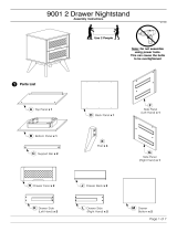
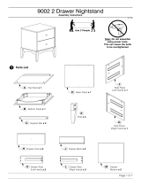
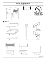
Furniture components:
2
3
1 x1
x1
x1
x1
Top Board
Bottom Board
Left Side Board
4 Right Side Board
Approx. 60 minutes
assembly time
2 people recommended
for assembly
Care instructions are
listed in the last step
of this manual
Read through all of
the instructions
before starting
Make sure you have all
parts and components
before discarding any
packing materials
Let’s get started!
Missing parts or hardware? Need assistance?
Contact us before returning your item. We're here to help!
609.256.9000 • cs@modway.com
x15 Back Board
x26 Middle Support
x4
7 Leg
x38 Drawer Front Board
x39 Drawer Back Board
x310 Drawer Left Board
x3
11 Drawer Right Board
x312 Drawer Bottom Board
What you need:
Phillips Head Screwdriver
Phillips
Provided hardware:
E
A
B
D
C
F
L
K
x6
x6
x18
x16
x22
x44
x8
x18
Screw M 6 x 8 mm
Cam Lock Ø15 mm
Cam Bolt Ø7.5 x 32 mm
Plastic Dowel Ø6 x 30 mm
Cam Cover Ø17 mm
Screw M 6 x 13 mm
G x12Screw M 10 x 33.5 mm
Cam Cover Ø15 mm
Cam Lock Ø12 mm
MDrawer Runner x3
N x1Anti Tipping Set
H x4Sleeve Nut
Ix1
Allen Key
J x3Push to Open
O x12Backply Stopper
P x12Screw M 4 x 19 mm

PAGE 3 OF 9
x6
x4
x6
x1
x2
x1
Cam Bolt Ø7.5 x 32 mm
Plastic Dowel Ø6 x 30 mm
Screw M 6 x 8 mm
Top Board
Middle Support
Bottom Board
HA R DWA R E
C O MPONENT S
2
1
6
B
D
E
Step 1
Step 2
x3Push to Open
J
x10
x8
x12
x1
x1
Cam Bolt Ø7.5 x 32 mm
Plastic Dowel Ø6 x 30 mm
Screw M 6 x 8 mm
Left Side Board
Right Side Board
H A R D W A R E
C O M P O NENT S
4
3
B
D
E
x6
x3
Screw M 6 x 13 mm
Drawer Runner
F
M

PAGE 4 OF 9
Step 3
Step 4
x10
x4
Cam Lock Ø15 mm
Cam Cover Ø17 mm
H A R D W A R E
A
C
x4
x1
x1
x1
Sleeve Nut
Allen Key
Bottom Board
Back Board
HA R DWA R E
C O M P O NENT S
5
2
H
I
x1
x1
Left Side Board
Right Side Board
COM P O NENT S
4
3
x1
Back Board
5
x4
Leg
7
x8Plastic Dowel Ø6 x 30 mm
D
x2
Middle Support
6

PAGE 5 OF 9
Step 5
Step 6
x6Screw M 10 x 33.5 mm
HA R DWA R E
H
x1
x1
Left Side Board
Right Side Board
C O M P O NENT S
4
3
x1
Bottom Board
2
x1
Back Board
5
x6
x4
x1
Cam Lock Ø15 mm
Cam Cover Ø17 mm
Top Board
H A R D W A R E
C O MPONENT S
1
A
C
x1
Left Side Board
3
x1
Right Side Board
4
x1
Back Board
5

PAGE 6 OF 9
Step 7
Step 8
x6
x24
x3
x3
x3
Cam Bolt Ø7.5 x 32 mm
Plastic Dowel Ø6 x 30 mm
Drawer Front Board
Drawer Left Board
Drawer Back Board
HA R DWA R E
C O MPONENT S
9
8
10
B
D
x3
Drawer Right Board
11
x3
x3
x3
x3
x6Screw M 10 x 33.5 mm
H A R D W A R E
CO M PO N EN T S
H
x3
x3
Drawer Left Board
Drawer Back Board
9
10
x3
Drawer Right Board
11
x3

PAGE 7 OF 9
Step 9
Step 10
x3
x3
x3
Drawer Front Board
Drawer Left Board
Drawer Back Board
HA R DWA R E
C O MPONENT S
9
8
10
x3
Drawer Right Board
11
x3
Drawer Bottom Board
12
x6
x6
Cam Lock Ø12 mm
Cam Cover Ø15 mm
K
L
x3
x3
L
KK
x12
x12
Screw M 4 x 19 mm
Backply Stopper
H A R D W A R E
O
P
x3
O
P
K

PAGE 8 OF 9
Step 11
Step 12
HA R DWA R E
x12
x3
Screw M 6 x 13 mm
Drawer Runner
F
M
x3

Nightstand assembly is complete
CA R I N G FO R Y O U R I T E M
Indoor use only.
Not contract grade.
Clean using a non-abrasive cloth
and a mild cleaner.
Never use harsh chemicals,
as they could damage the fi nish
or integrity of the item.
CONNECT WITH US!
Tag us @modway_furniture and #modway
for a chance to be featured.
Great job!
PAGE 9 OF 9
Max 35Kgs
Max 9.9Kgs
Max 9.9Kgs
Max 9.9Kgs

TIPPING RESTRAINTS KIT INSTALLATION GUIDANCE
N x 1
Different wall materials require unique wall fasteners.
Please consult your local hardware store to ensure you are using the correct hardware for you wall type.
Customer Service 609.256.9000 | www.modway.com
N
N
4
Grids Surface
1
2 3 4
5
Installation Instructions :
2. Please make a hole on the wall for attach the bracket (N) to the back of unit.
3. Attach bracket (N) on the wall using long screw (N) as shown.
Locate the other bracket (N) on the wall. Place furniture into position so both brackets (N) as shown.
4. Lace the end of the restrains strap through the larger hole in each bracket. Ensure the restrains strap with grids surface facing the inner
loops. Bring both ends together and slide the flat end through the locking end and draw it through until all slack is removed.
5. Make sure that the strap is securely laced & locked.
1. Attach bracket (N) securely to the back top of the furniture using short screw (N) provided.
N
N
N
N
/