HySecurity SlideDriver AC - 222 Relay Owner's manual
- Category
- Gate Opener
- Type
- Owner's manual

www.hysecurity.com
D0777
SlideDriver AC 222
Relay manual
DISCLAIMER
HySecurity relay-controlled hydraulic gate operators
do not meet current UL 325 Safety Standards and that
HySecurity recommends decommission and
replacement of all manufacturers’ relay-controlled
operators with modern Smart Touch™ based
operators, which fully comply with UL 325 safety
standards. By downloading and using this document
you acknowledge that HySecurity no longer provides
parts or technical support for those older operators.
Note
HySecurity accepts no responsibility, implied or
express, for claims arising from continued use of pre-
2001 relay-controlled operators.
OBSOLETE

222 SS, 222 E, 222 EX, 222 X1 SLIDE GATE
OPERATOR HANDBOOK
Hy-Security Gate Operators
Manufacturers and Designers of Hydraulic Systems
SS12
OBSOLETE

Cautionary Notes also see illustration on next page:
•Hy-Security gate operators are designed for vehicular traffic; not pedestrians. Direct
all pedestrian traffic to a separate walk-through gate, and clearly display the warning
signs on both sides of the vehicle gate.
• Verify that the gate operator is marked as appropriate for the type and usage class of
the gate. External sensors must be installed to protect against accidental entrapment in
both the opening and closing directions of gate travel.
•This type of gate operator must not be installed on the public, or non-secured side of
the gate. To minimize the risk of entrapment, assure that the installation includes
sufficient clearance between the gate and adjacent structures.
•Children must never be allowed to play on or around the gate.
•All access controls must be mounted at least six feet away from the gate and have a
security feature to prevent unauthorized use.
•Install entrapment protection devices and sensors devices appropriate for the type of
gate and usage class application: cover exposed rollers, screen across the face of the
gate, install electric edge sensors, photoelectric sensors, guard posts, and moving gate
alarms. Test all of your entrapment sensors to insure that they are working in the
proper manner.
• Install physical stops for the gate panel, in each direction. This will assure that the
gate does not accidentally travel farther than intended.
•Always make certain the operator is properly electrically grounded.
•Construct or screen automatic sliding gates, from the bottom of the gate to a minimum
height of four feet, so that a sphere 2 1/4" in diameter cannot pass through. The 2 1/4"
restriction also applies to the portion of the adjacent fence that the gate covers when
open.
•When constructing/installing sliding gates, always minimize the gap between gate and
fence. The gate must move freely in both directions. Never over-tighten a clutch or
relief valve to compensate for a stiff gate.
Automatic gate operators provide convenience and security to users. However, because these machines can
produce high levels of force it is important that all gate operator system designers, installers and end users be
aware of the potential hazards associated with improperly designed, installed or maintained systems. Keep in
mind that the gate operator is only one component of the total gate operating system. It is the joint responsi-
bility of the specifier, designer, purchaser, installer and end user to verify that the total system is safe for its
intended use. All parties should be aware that entrapment in a moving vehicle gate can cause serious injury or
death.
Important Information
Page 1 of 2 7/27/00 S44a
Minimize
Gap
READ THIS FIRST!READ THIS FIRST!
READ THIS FIRST!READ THIS FIRST!
READ THIS FIRST!
CommonCommon
CommonCommon
Common
IndustryIndustry
IndustryIndustry
Industry
SymbolsSymbols
SymbolsSymbols
Symbols Attention
–Take Note– –Danger–
Keep Away Possible
Pinch Point
Entrapment
Zone
OBSOLETE

Entrapment Protection DeviceEntrapment Protection Device
Entrapment Protection DeviceEntrapment Protection Device
Entrapment Protection Device
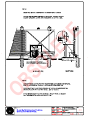
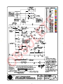
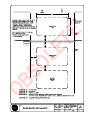
Schematic for Sliding Gates Schematic for Sliding Gates
Schematic for Sliding Gates Schematic for Sliding Gates
Schematic for Sliding Gates
This schematic view is not meant to recommend the only way to set up your configurtion,
but to point out the various elements of a proper automatic vehicular gate installation. The
gate operator itself is only one component in the total system. Always install a separate
pedestrian gate.
Page 2 of 2 6/1/00 S44b
Photocells for
both directions
each side of gate
2¼" safety mesh prevents
reach-through: height not
less than 48 inches
Warning signs
must be on both
sides
Gate edge
sensors
Gate edge sensor,
on leading edge
and trailing edge
Physical travel
stop, both ends
Photocells for
both directions
Physical travel
stop, both ends
Stop and reset
button
Audio
alarm
Access controls
at least six feet
away from gate
and operator
Guard posts
Keep this gap as
small as possible
Attention
NOTE: All wheels must be covered.
(Wheels and covers not shown for
clarity).
(By others)
(EACED 005 MK)
(By others)
(By others)
(aekph 001 thb) (eaced 005 mk)
(acal 001)
(By others)
(By others)
(aekph 001 thb)
Edge transmitter
(ERCTR 020)
OBSOLETE

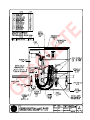
ëÉ~ííäÉI=ï~ëÜáåÖíçå
TITLE eóÇê~ìäáÅ=päáÇÉ=
DRAWING N UMBER:
SHT OF
TH I RD A NG LE PRO JE CTIO N
5
REVDRA WN
APPROVED
CH ECKED
DATE
DATE
DATE
6/1/00
MM/YY/DD
MM/YY/DD
KERI
SHOP
ENGRNG
PART NU MBER
N/A
--
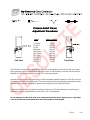
d~íÉ=léÉê~íçê
Gate Panel
Concrete Slab
Power transmission: Hydraulic motors to drive rail
Drive Rail
Polyurethane drive rail wheel tread
eliminates the high wear metal-to-metal
contact of conventional chain-drive systems.
9.75” Top of slab to top
of drive rail. 14.5”
26”
26”
Safety Mesh
Roll Pins for
perfect splices
OBSOLETE

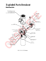
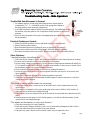
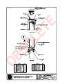
Exploded Parts Breakout
Parts, Part Numbers and KitsParts, Part Numbers and Kits
Parts, Part Numbers and KitsParts, Part Numbers and Kits
Parts, Part Numbers and Kits
Slide Gate Operator Exploded Parts Breakout
Hydraulic Motor W/FTGS (2)
222 X1, 444 XS: HMOMO K24 WRS
All others: HMOMO K10 ERS
Motor Mount Pin
and Retaining Bolt
MSLDU 012 SSK (2)
Motor Mount Arm
Upper: MSLDU 042 T
Lower: MSLDU 042 B
Heater Location
(Optional)
Limit Switch (2)
111LS: ESWLS 224 111
All others:
Left Side: ESWLS 224 SHRT
Right Side: ESWLS 224 LONG
Drive Wheels
222 EX, X1& 444 series: MSLDW 008 HY
All others: MSLDW 006 HY
111 LS Idler Wheel
MSLDW 006 I
Wheel Clamping Assembly
MSLDU 070 CAST
10 Ga Steel Chassis
Solenoid
Valve
Pressure
Gauge
"E" Manifold
HMAMA 222 BVK
Electric Motor
with Pump and
Reservoir
Pushbutton Station
On/Off
Switch
Electric
Control
Panel
AWOG with Manifold
Power Units are Detailed by
Operator Series on next two pages
OBSOLETE

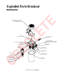
Exploded Parts Breakout
Related Pump PacksRelated Pump Packs
Related Pump PacksRelated Pump Packs
Related Pump Packs
Quick Disconnects
socket--HSFQD 002 S
plug--HSFQD 002 P
Quick Disconnects for XS only:
socket--HVAQD 004 S
plug--HVAQD 004 P
Brake Manifold (Complete)
HMAMA 222 BVK
Brake Valve
HVABK CBA 1500
Breather Cap
HRSBC 001
Pump Pack Complete
(less motor)
HPPPU H13 S3E
Soft Start Manifold
(Complete Kit)
HMAAC 222 SSK
Pressure Gauge
HASGA 120 MINI
Directional Valve
HVADI DEL 2P
Directional Valve Coil
HVASO DEL 024
Reservoir
HRSRS 004
Coupler
MPTCO 010 9T
Electric Motor EX, CX, X1, XS
1 phase--EMOMO 010 2.0B
3 phase--EMOMO 030 2.0B
XS: 3 phase only--EMOB6 236 5.0C
Quick Stop Valve
HVAQS 001 C
AWOG Hose
HMAAC 111 H
Quick Stop Coil
HVASO DEL QSAC
EX, CX, X1, XS Models
Relief Valve
HVARE LAN
OBSOLETE

Exploded Parts Breakout
Related Pump PacksRelated Pump Packs
Related Pump PacksRelated Pump Packs
Related Pump Packs
Electric Motor LS, SS, CF, E, CE
1 phase--EMOMO 010 1.0B
3 phase--EMOMO 030 1.0B
Coupler
MPTCO 010 9T
Pump Pack Complete (less motor)
LS--HPPPU H11
SS, CF--HPPPU H12 D
E, CE--HPPPU H12 DE
Breather Cap
HRSBC 001
Brake Valve
HVABK CBA 1500
Brake Manifold (Complete)
HMAMA 222 BVK
Quick Disconnects
(not available on LS)
socket--HSFQD 002 S
plug--HSFQD 002 P
Pressure Gauge
HASGA 120 MINI
Directional Valve
HVADI DEL 2P
Directional Valve Coil
HVASO DEL 024
Reservoir
HRSRS 004
Optional:
Pressure Relief Valve
HVARE FAN
Quick Stop Valve
HVAQS 001 C
Quick Stop Valve Coil
HVASO DEL QSAC (AC operators)
HVASO DEL QSDC (DC operators)
LS, SS, CF, E, CE Models
OBSOLETE

OBSOLETE

OBSOLETE

OBSOLETE

OBSOLETE

1. See drawings S13A & S13B for concrete slab size, operator footprint, and spacing dimensions. With the
aid of the template enclosed inside the operator, locate the operator with clearance of 1-3/4" to the gate panel.
2. Mount operator to pad with a minimum of four concrete anchor bolts of 1/2" diameter.
3. Remove the plastic shipping plug on the pump manifold and replace it with the vented cap supplied. You
will find it in a box with the plastic limit ramps.
4. Entrapment Protection - minimum safeguards:
A. Since automatic gates are not intended for pedestrian use, always install a separate pedestrian walkway
and access gate. Install signs which direct persons to use the pedestrian gate, and to not enter through
the vehicle gate.
B. Be certain that all open gate rollers are completely guarded by covers.
C. Be certain that the gate has been constructed such that the opportunity for persons to reach through any
opening have been minimized. A sphere 2-1/4" must not pass through any part of the gate, or the fence
adjacent to the gate when fully open. It may be necessary to install screening to prevent reach through
injury.
D. Placement of physical stops for maximum open and maximum close is essential to prevent any over
travel that might allow the gate to fall. The limit ramps are not to be used as gate stops.
E. Be certain that all access controls are located at least a six foot distance from the gate, to reduce the
possibility of any attempt to reach through in order to operate the gate.
F. Be certain to mount at least two of the enclosed 8-1/2" x 11" warning placards on each side of the gate
to warn users of the hazards of a power operated gate.
G. Button Station Operation: Be certain to mount a warning placard near each button station that warns
that the area must be clear before operating the gate. If there are no entrapment protection sensors to
guard the open and close operation of the gate, the push button station must be wired for constant hold
operation only. This is achieved by cutting jumper wires in the control circuit, see drawing E63T2 or
E55T2 for the 111 LS model.
H. Automatic Operation: Entrapment protection sensors must be installed to guard both the opening and
closing of the gate. Install two photo electric eyes, or attach a minimum of two edge sensors to create a
reversing function for each direction of gate travel. All sensors guarding the closing direction connect
to terminals #1 and #6 in the control box. All sensors guarding the opening direction connect to termi-
nals #9 and #6. See drawing #E41 for mounting and connection details of the edge sensors.
Caution: vehicle detectors are not entrapment protection sensors.
5. Connect appropriate power wiring. Be certain to oversize supply conductors to allow for voltage drop,
especially for single phase machines. Follow the wire size schedules (drawing# E16a,b). Machines that are to
operate on voltages above 120 do not need a neutral wire. Route conduit to the front left corner of the control
box. Wirenut the supply power wires to the loose wires at the back of the on/off switch. Be certain to connect
a ground wire.
Installation Instructions forInstallation Instructions for
Installation Instructions forInstallation Instructions for
Installation Instructions for
Hydraulic Sliding Gate OperatorsHydraulic Sliding Gate Operators
Hydraulic Sliding Gate OperatorsHydraulic Sliding Gate Operators
Hydraulic Sliding Gate Operators
(Except DC versions)(Except DC versions)
(Except DC versions)(Except DC versions)
(Except DC versions)
Page 1 of 3 5/31/00 S16a
OBSOLETE

6. Verify that the primary tap of the control transformer is connected to match the supplied voltage. It is especially
important to distinguish between 208 and 230 volt supplies. The various voltage taps are identified by a label on
the transformer or in the electrical drawings.
7. Test the basic functions of the operator first, before connecting any external control wiring. If your operator
is equipped with vehicle detectors, be certain that they are connected to a loop or un-plugged so that they do not
cause interference with the function of the machine. If the motor turns, but nothing moves, reverse two poles of
a three phase power source. Also be certain that the hose quick connectors are firmly engaged. If the open and close
functions are reversed, refer to step 9.
8. All operators are manufactured to be right hand. If reversing the hand is necessary, first swap locations of the
two limit switches (do not change the wires, just move the limit switches, the cords are long enough). On 222
models, the handing can be changed by simply unplugging and reversing the limit wiring on the left side of the
control enclosure. A label is affixed on the control panel which describes this procedure in more detail. It is also
necessary to reverse the two hydraulic hoses going to the pump. On the 111 LS operators, a wrench will be required
to remove and reattach the hoses. All 222 models are provided with hydraulic quick connectors which require no
tools to reverse handing. Run the operator to verify correct functioning. If the hydraulic hoses were incorrectly
reversed, the gate will move in the opposite direction than commanded. If the limit switch cords were incorrectly
reversed, the operator would not stop when the gate reached its full travel. Never reverse wiring to the push button
station.
9. After testing the basic functions, follow our electrical connection diagrams to add any accessories or external
control wiring. Test the operator functions again.
10. Install drive rail on gate panel at the specified height. The drive rail must be close to the center of the cutout
in the operator housing as it passes between the drive wheels. Check to see that the arms supporting the wheels
are at similar angles from horizontal. Be sure that the drive rail maintains a consistent height in relation to the
operator wheels, throughout the travel of the gate. (This may not be level or parallel with the gate frame because
the gate panel and the fence may not be level.) The maximum up and down variance of the drive rail, as it passes
between the wheels, is one inch for the entire length of the gate travel. The point at which the rail should pass
between the wheels is marked on the exterior of the operator housing.
11. Actuate the toggle clamp to grip the wheels onto the drive rail. Gauge the tension on the red spring. If more
or less tension is needed, release the toggle clamp, adjust the nut on the threaded rod that penetrates the spring.
A compression to 2" in height will be sufficient even for very heavy gates. Slightly less compression should be
used for gates that weigh under 1000 pounds, or roll very easily. 2 1/8" compression is the maximum for the 111
LS operator.
12. Adjust the lever arms of limit switches to maintain at least 1/4" clearance from the underside of the drive rail.
This will avoid false tripping of the limits (see drawing# S 22). The limit switch arm should be approximately in
the center of the rail channel. If adjustment is required, remove the limit arm before bending. This will avoid
breaking the head of the switch. Locate the plastic limit ramps on the underside of the drive rail to control maximum
travel of the gate in the open and close direction. Mount the limit ramps to trip the limit switches approximately
three inches ahead of the desired gate stopping position. This clearance is needed for gate deceleration travel, after
the limit switch has been tripped.
13. Check the "soft stop" open timer, which is mounted on top of the control relay. The label on the timer dial shows
the minimum and maximum settings. In operation the timer only needs to be set long enough for the gate to coast
to a smooth stop after opening. There is no bad effect if the timer is set for too long, except that the operator cannot
be started closed until this timer times out. There is no timer adjustment for the close direction.
Page 2 of 3 5/31/00 S16b
OBSOLETE

14. Set the maximum run timer, which is located at the extreme right, inside of the electric panel. The range is
adjustable to 10 minutes. Set the timer for more than twice the amount of time needed for the gate to traverse the
opening.
ADJUSTMENT OF ACCESSORIES AND INFORMATION ABOUTADJUSTMENT OF ACCESSORIES AND INFORMATION ABOUT
ADJUSTMENT OF ACCESSORIES AND INFORMATION ABOUTADJUSTMENT OF ACCESSORIES AND INFORMATION ABOUT
ADJUSTMENT OF ACCESSORIES AND INFORMATION ABOUT
TWO FOOT/SECOND OPERATORSTWO FOOT/SECOND OPERATORS
TWO FOOT/SECOND OPERATORSTWO FOOT/SECOND OPERATORS
TWO FOOT/SECOND OPERATORS
1. Set "timer to close" accessory for desired delay. This optional timer is located on the left side of the main control
relay. The range is adjustable from 1 to 30 seconds. The timer will close the gate from any position, but all open
and safety signals must be absent.
2. All operators, except 111 LS and 222 SS, have a reverse delay timer mounted at near center of the control panel.
The delay is adjustable from .3 to 3 seconds, and works together with the soft stop feature to provide smooth
reversing. Larger gates will need a longer delay to allow time for the momentum of the gate to be stopped. Most
gates will only need a second or less. The time needed to stop and reverse a gate is partly a function of the optional
brake valves that are included with many models. See number three for their correct adjustment.
3. All two foot per second operators, as well as any operator that is intended to drive gates in excess of 1,000 pounds
should be equipped with the "E" option, which adds a reverse delay and hydraulic brakes, to rapidly decelerate
a gate. The positioning of the limit ramps should be 6 inches ahead of full gate travel to give some space for
deceleration. Adjustment of the brake valves, one for each direction, affects the limit switch adjustment. If
adjustment is necessary, loosen the 9/16" lock nut on the end of the brake valves (located on the front side of the
hydraulic pump). Turn the adjustment stem with an allen wrench. The adjustment works opposite of typical, in
that a counter-clockwise adjustment will stop the gate more rapidly. If the adjustment is set too loose, the gate will
coast too far. If the adjustment is set too tight the gate speed will decrease. Be certain to re-tighten the locking
nut when the adjustment is complete.
Page 3 of 3 5/31/00 S16c
OBSOLETE

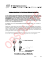
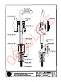
Use and Adjustment of the Manual Release MechanismUse and Adjustment of the Manual Release Mechanism
Use and Adjustment of the Manual Release MechanismUse and Adjustment of the Manual Release Mechanism
Use and Adjustment of the Manual Release Mechanism
All slide gate series operators come equipped with a toggle handle manual release mechanism to disengage
the drive wheels from the drive rail. The manual release is located under the electric control panel and to the
right of the hydraulic motors. To disengage the drive wheels, simply pull the aluminum handle down.
USE CAUTION: at first the toggle handle will rapidly pop down, as the loaded spring releases. This action
will cause the lower drive wheel to drop and disengage from the drive rail. When the coupling nut on the
threaded rod drops to its lowest position it will push on the base of the operator which will cause the upper
drive wheel to lift and disengage from the drive rail.
For shipment, a piece of wood was placed between the coupling nut and the chassis. If the wood is still in
place, discard it.
If the drive rail has been installed at the correct height to the chassis, the manual toggle release mechanism
will equally spread both wheels away from the drive rail. If the rail has been mounted higher than specified,
it may be necessary to insert a 3/8" bolt into the bottom of the coupling nut which will create additional lift
clearance for the upper drive wheel when manually released. If used, adjust the 3/8" bolt so the drive wheels
spread equally when the manual toggle release is fully disengaged.
The coupling nut must always be adjusted correctly so the wheels provide a strong clamping force on the
drive rail. The red spring should measure 2" to 2-1/8" in height when under correct compression.
For assistance call your Distributor.For assistance call your Distributor.
For assistance call your Distributor.For assistance call your Distributor.
For assistance call your Distributor.
Manual Release Handle
Coupling Nut for Spring
Tendion Adjustment
Red Spring Controls
Wheel Grip
5/10/00 S40-1
OBSOLETE

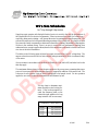
Pushbutton Control Wiring
16 ga 125' Maximum
14 ga 200' Maximum
12 ga 300' Maximum
10 ga 500' Maximum
Wire Size SchedulesWire Size Schedules
Wire Size SchedulesWire Size Schedules
Wire Size Schedules
for 1/2-hp through 5-hp motors
Supplying a gate operator with the right electrical service is crucial to the way the performance of
the operator the life of its electrical components. If the wire size used is too small, the voltage loss—
especially during motor starting—will prevent the motor from attaining its rated horsepower. The
percent of horsepower lost is far greater than the percentage of the voltage loss. A voltage loss could
also cause the control components to chatter while the motor is starting, substantially reducing their
life due to the resultant arcing. There is no way to restore the lost performance resulting from
undersized wires, except to replace them; therefore it is much more economical to choose a sufficient
wire size at the initial installation.
The tables on the following page are based on copper wire and allow for a 5% voltage drop. The
ampere values shown are the service factor ampere rating (maximum full load at continuous duty)
of the motor.
Always connect in accordance with the National Electrical Code, article 430, and other local codes
that may apply.
The maximum distance shown is from the gate operator to the power source; assuming that source
power is from a panel box with adequate capacity to support the addition of this motor load. The
values are for one operator, with no other loads applied to the branch circuit. For two operators
applied to one circuit, reduce the maximum allowed distance by half.
Use this chart to determine maxi-
mum allowable control wiring dis-
tance. If the location required ex-
ceeds the distances listed on the
chart at the right, addition of a long
range interface will be neccessary.
4/14/00 E16a
OBSOLETE

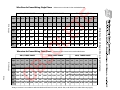
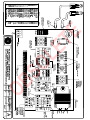
Wire Size for Voltage Drop Over Distance
E16b
Wire Sizes for Power Wiring, Single Phase Distances are shown in the unshaded boxes
Wire Gauge Wire Gauge
Always connect in accordance with the National Electrical Code, article 430, and other local codes that may apply.
Wire sizes for Power Wiring, Three Phase Distances are shown in the unshaded boxes
115 V, SINGLE PHASE 208 V, SINGLE PHASE 230 V, SINGLE PHASE
Amps 10.0 11.06 14.4 27.2 NA NA 5.5 6.1 7.6 14.2 16.2 NA 5.0 5.8 7.2 13.6 14.8 27.0
Horse 1/2hp 3/4hp 1hp 2hp 3hp 5hp 1/2hp 3/4hp 1hp 2hp 3hp 5hp 1/2hp 3/4hp 1hp 2hp 3hp 5hp
Power
12ga 90 75 60 30 290 260 205 110 100 350 300 245 130 120 65
10ga 140 120 100 50 460 415 330 175 155 560 480 385 205 190 105
8ga 220 190 155 80 725 650 525 280 245 880 760 610 325 300 165
6ga 350 300 245 130 1,150 1,040 835 445 390 1,400 1,120 975 515 475 260
4ga 555 480 385 205 1,825 1,645 1,320 710 620 2,220 1,915 1,550 815 750 410
2ga 890 765 620 330 2,920 2,630 2,110 1,130 1,000 3,550 3,060 2,465 1,305 1,200 660
208 V, THREE PHASE 230 V, THREE PHASE 460 V, THREE PHASE
Amps 2.7 3.1 4.2 6.5 6.7 16 2.4 3.0 3.8 6.2 6.4 15.4 1.2 1.5 1.9 3.1 3.2 7.7
Horse 1/2hp 3/4hp 1hp 2hp 3hp 5hp 1/2hp 3/4hp 1hp 2hp 3hp 5hp 1/2hp 3/4hp 1hp 2hp 3hp 5hp
Power
12ga 590 510 375 245 235 100 730 585 460 280 270 115 2,915 2,350 1,850 1,130 1,100 455
10ga 930 810 600 390 375 160 1,160 930 730 450 435 180 4,640 3,710 2,930 1,800 1,740 725
8ga 1,475 1,285 950 615 595 250 1,835 1,470 1,160 710 690 285 7,340 5,870 4,650 2,840 2,750 1,150
6ga 2,350 2,045 1,510 975 945 400 2,925 2,340 1,845 1,130 1,095 455 11,700 9,350 7,400 4,550 4,400 1,800
4ga 3,720 3,240 2,390 1,545 1,500 630 4,625 3,700 2,920 1,790 1,735 720 18,500 14,800 11,700 7,200 7,000 2,900
OBSOLETE

OBSOLETE

OBSOLETE
Page is loading ...
Page is loading ...
Page is loading ...
Page is loading ...
Page is loading ...
Page is loading ...
Page is loading ...
Page is loading ...
Page is loading ...
Page is loading ...
Page is loading ...
Page is loading ...
Page is loading ...
Page is loading ...
Page is loading ...
Page is loading ...
Page is loading ...
Page is loading ...
Page is loading ...
Page is loading ...
Page is loading ...
Page is loading ...
Page is loading ...
Page is loading ...
Page is loading ...
Page is loading ...
-
 1
1
-
 2
2
-
 3
3
-
 4
4
-
 5
5
-
 6
6
-
 7
7
-
 8
8
-
 9
9
-
 10
10
-
 11
11
-
 12
12
-
 13
13
-
 14
14
-
 15
15
-
 16
16
-
 17
17
-
 18
18
-
 19
19
-
 20
20
-
 21
21
-
 22
22
-
 23
23
-
 24
24
-
 25
25
-
 26
26
-
 27
27
-
 28
28
-
 29
29
-
 30
30
-
 31
31
-
 32
32
-
 33
33
-
 34
34
-
 35
35
-
 36
36
-
 37
37
-
 38
38
-
 39
39
-
 40
40
-
 41
41
-
 42
42
-
 43
43
-
 44
44
-
 45
45
-
 46
46


HySecurity SlideDriver AC - 222 Relay Owner's manual
- Category
- Gate Opener
- Type
- Owner's manual
Ask a question and I''ll find the answer in the document
Finding information in a document is now easier with AI
Related papers
-
HySecurity HTG Relay Owner's manual
-
-
-
-
-
-
-
-
-
Other documents
-
 Hy-Security 222 EX Installation and Maintenance Manual
-
 Calimet CM9-631 User manual
-
Chamberlain HS670 User manual
-
-
DKS 9200 Pre 2016 User manual
-
-
 Hy-Security SwingRiser 30 Installation And Reference Manual
-
-
-


