06/08 505027M
*2P0608* *P505027M*
Page 1
KITS AND ACCESSORIES
MISCELLANEOUS Litho U.S.A.
E2008 Lennox Industries Inc.
Dallas, Texas, USA 505027M
06/08
Supersedes 02/2005
IMC 4−STAGE INTERFACE
(FS1) 4H/4C MODULE KIT
INSTALLATION INSTRUCTIONS FOR FS1 (4 HEAT/4 COOL) KIT (86M72)
USED WITH THE L CONNECTION® NETWORK
Shipping and Packing List
Package 1 of 1 contains:
1− Four stage interface (FS1) 4H/4C board (A138)
1− J202/201 harness
3− Wiring diagrams
1− Bag assembly containing:
4− 6−32 X 7/8" TFS hex head screws
Application
The 4H/4C kit provides the additional 24VAC demand in-
puts to the IMC for applications that use third−party thermo-
stat or DDCs that have up to 4 heat and/or 4 cool outputs.
This kit does not apply to heat pump units.
Installation
WARNING
Improper installation, adjustment, alteration, ser-
vice or maintenance can cause property damage,
personal injury or loss of life. Installation and ser-
vice must be performed by a qualified installer or
service agency.
1. Disconnect all power to unit and open control panel.
2. Carefully remove FS1 board from protective packag-
ing. Install the board near the A55 IMC main control
board using provided screws. Refer to the IMC manual
provided with the unit for the location of the IMC.
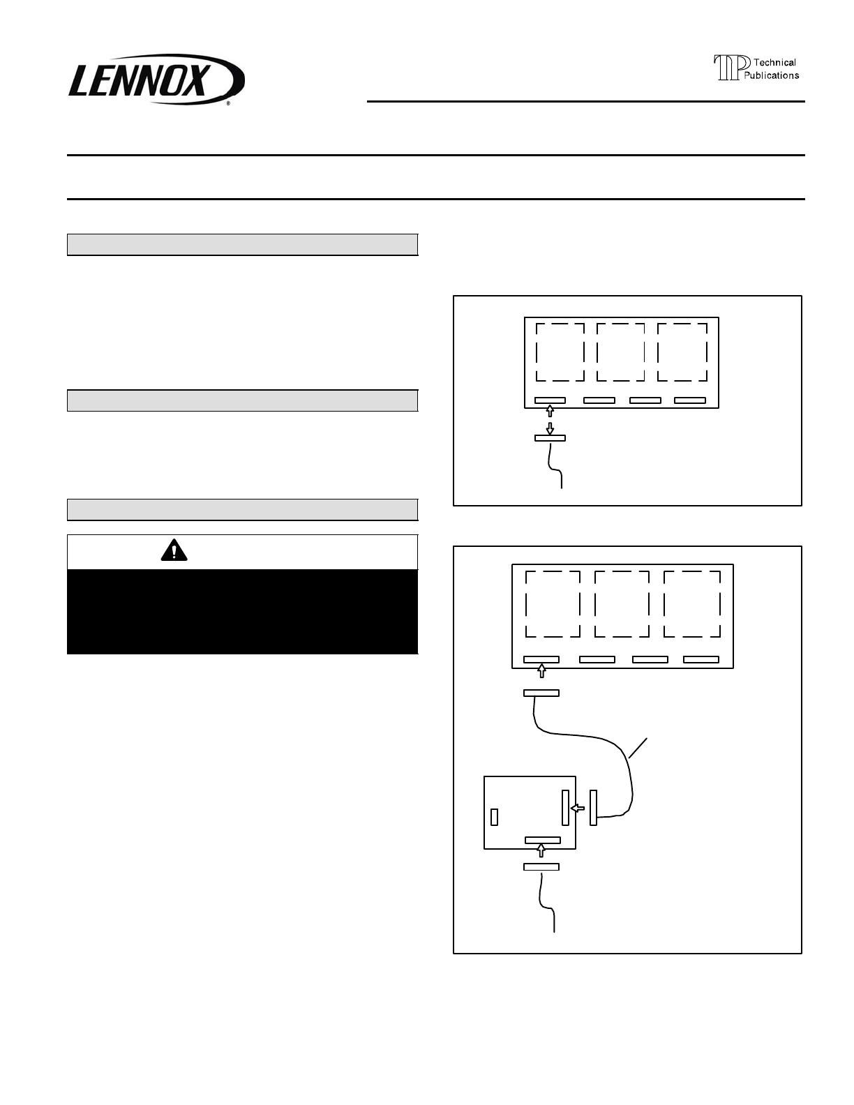
3. Disconnect J110 jack from IMC board. See figure 1.
Wires leading to connectors are stamped with labels
that identify the plug.
4. Connect J110 to P200 on the FS1 board. See figure 2.
5. Connect the kit harness between P201 on the FS1
board and P110 on the IMC board. See figure 2.
6. Locate the wiring diagram which lists the appropriate
number of heating and cooling stages for the thermo-
stat to be used. Make thermostat wiring connections
to TB17 on the FS1 board as shown on the diagram.
Affix the diagram on top of the existing control section
diagram on the unit panel.
NOTE − Be sure to install the jumper wires where indi-
cated on TB17.
7. Restore power to unit and refer to IMC manual for
start−up.
8. Set ECTO 6.01 to option 12. Refer to the IMC manual.
A55 (IMC)
P110 P111 P112 P113
TO TB1
J110
Figure 1. Disonnect J110
A55 (IMC)
KIT HARNESS
P110 P111 P112 P113
TO TB1
J110
A138 (FS1)
J202
J201P201
P200
TB17
Figure 2. Connect J202/201 Harness
