Page is loading ...

1PLC0012 rev. A.
Title: PLX2 Faceplate Replacement
Bulletin #: PLC0012
Issue Date: 9 April 2008
Models Affected: All PLX2 (not original PLX series)
Bulletin Revision: Rev. A
Production Range: All
Service Bulletin
Description
This bulletin describes the recommended procedure for replacing the faceplate on a PLX2 amplifier. (The procedure may be more
involved than it first seems, because there are mounting screws hidden behind the faceplate labels.)
Parts and tools needed
• Faceplate (QSC part number CH-000426-00)
• Faceplate labels: model, LED lens, and gain (see table)
• #3 Philips screwdriver
• 7/16” nutdriver
• Pliers
Passionate About Sound
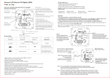
2
3
4
1
6
5
Left side Right side
Model LED lens Gain
PLX1104 LB-000578-00 LB-000526-00 LB-000585-00
PLX1804 LB-000579-00 LB-000526-00 LB-000585-00
PLX1802 LB-000580-00 LB-000526-00 LB-000584-00
PLX2502 LB-000581-00 LB-000526-00 LB-000584-00
PLX3102 LB-000582-00 LB-000526-00 LB-000584-00
PLX3602 LB-000583-00 LB-000526-00 LB-000584-00
Procedure
Removal of the old faceplate
1. Unplug the amplifier from the AC mains and let it sit for at least five minutes to allow internal voltages to bleed down.
2. Remove bottom cover (1).
3. Pull both gain control knobs (2) straight off their shafts.
4. Remove the gain control mounting nuts and lockwashers on the front of the faceplate. Separate the gain/display board from
the faceplate.
5. Peel off the gain label (3) and the LED lens label (4) under it. Once
you get an edge raised on a label, you might need to grip it with
pliers to pull it off the rest of the way. Warming the label with a
hair dryer may make it easier to peel.
6. Behind the faceplate, squeeze the mounting tabs of the power
switch (5) and push it out of its mounting hole.
7. Using pliers, disconnect the wires from the power switch.
8. Peel off the model label (6).
9. Remove the faceplate mounting screws. There are two on each
side panel behind the rack mounting ears and two on the front,
where the labels were. Remove the faceplate.
Table 1. Faceplate labels needed, by amp model
Figure 1. The PLX2 faceplate and associated parts

2PLC0012 rev. A.
Contact information
This bulletin is available for download from the Service Bulletins page in the
Tech Support
section of the QSC Audio Web site:
http://www.qscaudio.com/support/technical_support/bulletins.htm. If you need any further information regarding this
service procedure, please contact QSC Technical Services at the addresses or numbers below.
Telephone:
1-800-772-2834 (within USA only)
+1 (714) 957-7150
Fax:
+1 (714) 754-6173
E-mail:
Web sites:
www.qscaudio.com (product info/support)
www.qscstore.com (on-line accessory and replacement component sales)
Postal and parcel address:
QSC Audio Products, LLC
Technical Services Group
1665 MacArthur Blvd.
Costa Mesa, CA 92626 USA
Installing the new faceplate
10. Put the new faceplate in place and install all six mounting screws. Note
that the faceplate’s side panel mounting holes are not threaded. The self-
tapping mounting screws for these holes are meant to cut threads in the
cast aluminum, so they may be difficult to tighten; when tightening a
self-tapping screw, you might sometimes need to loosen it slightly before
tightening further.
11. Peel the backing from the label with the amp model number (6) and
carefully place it on the left side of the faceplate. Press it firmly in place.
12. Pass the switch wires through the faceplate opening for the power
switch (5). Attach them to the switch (Figure 2).
13. Orient the switch as shown in Figure 2 and press it into the faceplate
opening. It will snap into place.
14. Reinstall the gain/display board. Place the lockwashers and nuts and tighten them snugly, but be careful not to overtighten
them.
15. Peel the backing from the LED lens label (4) and carefully place it on the right side of the faceplate. Press it firmly in place.
16. Place the gain label (3) on top of the LED
lens label. Press it firmly.
17. Press the knobs (2) onto the gain control
shafts.
18. Reinstall the bottom cover (1) and make sure
the amp works properly.
CARLINGSWITCH
15A 250VAC
20A 125VAC
723R
Red
Black
wire
wire
This end
toward top
of amplifier
Rear support for power amplifiers
Especially in a mobile or portable sound system, a power amplifier
mounted in an equipment rack should also be supported at the rear to
prevent damage, such as bending or cracking, to the faceplate.
The QSC Technical Services Group offers rear
rack ear kits for securing an amplifier to the
rack’s real rails. They are available in two
lengths, 3 and 7 inches (75 mm and 177 mm).
Each kit includes two L-bracket ears and the
necessary screws and hardware.
The QSC part number for the
shorter rear rack ear kit is
FG-000031-00. The
part number for the
longer kit is
FG-000081-00.
Figure 2. Wiring and orientation of the power
switch.
/