Page is loading ...

v
OWNER’S
MANUAL
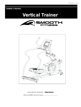
CAUTION: WEIGHT ON THIS PRODUCT SHOULD NOT EXCEED 136KG / 300LBS.
VERSION: 20130108
Product May Vary Slightly From Picture
MADE IN TAIWAN
VT-3.4 VERTICAL TRAINER

2
“SAFETY INSTRUCTION”
WARNING: To reduce the risk of serious injury, read the following safety instructions before using the
Climber.
1. Read all warnings posted on the equipment
2. Read this Owner's Manual and follow it carefully before using the equipment. Make sure that it is properly assembled and tightened
before use
3. We recommend that two people be available for assembly of this product
4. Keep children and pets away from the equipment. Do not allow children and pets to use or play on the equipment .Always keep children
and pets away from the equipment when it is in use
5. It is recommended that you place this exercise equipment on an equipment mat
6. Set up and operate the equipment on a solid level surface. Do not position the equipment on loose rugs or uneven surfaces
7. Inspect the equipment for worn or loose components prior to each use
8. Tighten / replace any loose or worn components prior to using the equipment
9. Consult a physician prior to commencing an exercise program. If, at any time during exercise, you feel faint, dizzy, or experience pain,
stop and consult your physician
10. Follow your physician's recommendations in developing your own personal fitness program
11. Always choose the workout which best fits your physical strength and flexibility level. Know your limits and train within them. Always use
common sense when exercising
12. Before using this product, please consult your personal physician for a complete physical examination.
13. Do not wear loose or dangling clothing while using the equipment
14. Never exercise in bare feet or socks; always wear correct footwear, such as running, walking, or cross-training shoes
15. Be careful to maintain your balance while using, mounting, dismounting, or assembling the equipment loss of balance may result in a fall
and serious bodily injury
16. Keep both feet firmly and securely on the Foot Pedals while exercising
17. The equipment should not be used by persons weighing over 300 pounds /136 kgs
18. The equipment should be used by only one person at a time
19. The equipment is for semi-commercial, light-commercial and home usage
20. Maintenance: Replace the defective components immediately and / or keep the equipment out of use until repair the equipment
completely.
21. Make sure that adequate space is available for access to and passage around the equipment; keep at least a distance of 1 meter from
any obstruction object while using the machine
WARNING: Before starting any exercise or conditioning program you should consult with your personal physician to see if you require a
complete physical exam. This is especially important if you are over the age of 35, have never exercised before, are pregnant, or suffer from
any illness
READ AND FOLLOW THE SAFETY PRECAUTIONS. FAILURE TO FOLLOW THESE
INSTRUCTIONS CAN RESULT IN SERIOUS BODILY INJURY

3
“ASSEMBLY PARTS”
Unpack the box in a clear area. Follow the List of Assembly Parts below to check and make sure all assembly parts are
present and in good condition. Do not dispose of the packing material until the assembly process is completed. Assembly
tools and hardware kit have included for you to use when assembling the product
Console Upper Cover
Console Bottom Cover
Console Sleeve
Upright Post Assembly
Fixed Handlebar
Upper Handlebar
Pedal
Sliding Rail
Upright & Handlebar
Sleeve
Nut & Leveler
Front & Rear
Stabilizer
Main Frame Assembly
Linkage Plug
Rail Sleeve
Securing Cap
Pedal Support Arm
Handrail Base Cover
Pedal Bottom Case
Adaptor

4
“HARDWARE IDENTIFICATION CHART”
Unpack the box in a clear area. Follow the List of Hardware Kit below. This chart is provided to help identify the hardware
used in the assembly process. Place the washers, the end of bolts, or screws on the circles to check for the correct
diameter. Use the small scale to check the length of the bolts and screws. Do not dispose of the packing material until your
trial period has expired
NOTICE: The length of all bolts and screws except those with flat heads is
measured from below the head to the end of the bolt or screw. Flat head
bolts and screws are measured from the top of the head to the end of the
bolt or screw
After unpacking the unit, you will notice that the package includes 3 bags of hardware (HARDWARE KIT A,
HARDWARE KIT B and HARDWARE KIT C).
Assembly’s Step 1, 2, 3, 7, 8: Using HARDWARE KIT A
Assembly’s Step 9, 10, 11: Using HARDWARE KIT B
Note:
a. Please review below to know the content of each hardware kit (A and B)
b. Some small parts may have been pre-attached for shipping. If a part is not in the hardware bag, check to see if it has
been pre-assembled
HARDWARE KIT A
Part No. and Description
Q’TY
79 Lock Washer (M8)
6 pcs
80 Washer (8x16x2.0t)
2 pcs
93 Bolt (M6xp1.0x25mm)
2 pcs
94 Bolt (M8xp1.25x16mm)
4 pcs
101 Bolt (M8xp1.25x90mm)
2 pcs
106 Bolt (M8xp1.25x90mm)
2 pcs

5
“HARDWARE IDENTIFICATION CHART”
109 Carriage Bolt (M8xp1.25x90mm)
2 pcs
HARDWARE KIT A
Part No. and Description
Q’TY
112 Nylon Nut (M8xp1.25)
4 pcs
131 Self-Tapping Screw, Flat Head (M4x10mm)
6 pcs
HARDWARE KIT B
Part No. and Description
Q’TY
79 Lock Washer (M8)
1 pcs
80 Washer (8x16x2.0t)
1 pcs
88 Self-Tapping Screw, Flat Head (M4x16mm)
4 pcs
90 Bolt (M5xp0.8x25mm)
4 pcs
91 Bolt (M5xp0.8x15mm)
4 pcs
98 Bolt (M6xp1.0x15mm)
4 pcs
99 Bolt (M6xp1.0x35mm)
100 Bolt (M8xp1.25x45mm)
4 pcs
1 pcs
110 Nylon Nut (M6xp1.0)
4 pcs

6
“BEFORE YOU BEGIN”
Thank you for choosing the Smooth Fitness Vertical
Trainer. We take great pride in producing this quality
product and hope it will provide many hours of quality
exercise so that you may reach your fitness goals.
Yes, it's a proven fact that a regular exercise
program can improve your physical and mental health.
Too often, our busy lifestyles limit our time and
opportunity to exercise. This equipment provides a
convenient and simple method to begin your journey
to get your body in shape and achieve a happier and
healthier lifestyle.
Before reading further, please review the drawing
below and familiarize yourself with the parts labeled
below. Read this manual carefully before using the
equipment.
THE FOLLOWING TOOLS ARE INCLUDED FOR ASSEMBLY:
Console
Upper Handlebar
Spring Knob
Main Frame
Pedal
Adjustable Rear Stabilizer EndCap
Pedal Rail
Hand Pulse
Sensor
ALLEN WRENCH
(5 mm)
WRENCH
(10 & 13 mm)
Sliding Roller
PHILLIPS
SCREWDRIVER (6mm)

7
“ASSEMBLY INSTRUCTIONS”
STEP 1 –
Front Stabilizer
Assembly
a. Attach the Front Stabilizer (2) to
the Main Frame (1).
b. Fully tighten the two Washers (8x16x2.0t)(80), two Lock Washers (M8)(79) and two Bolts (M8xp1.25x90mm)(101)
that attach to the Front Stabilizer (2) to the Main Frame (1).
STEP 2 –
Sliding Rail Assembly
NOTE: For shipping purpose, the 1pcs Washer (8x16x2.0t)(80), 1pcs Lock Washer (M8)(79) and 1pcs
Bolt (M8xp1.25x20mm)(103) are pre-installed in the Main Frame (1) as pictured on the left.
a. Remove the 1pcs Washer (8x16x2.0t)(80), 1pcs Lock Washer (M8)(79) and 1pcs Bolt
(M8xp1.25x20mm)(103) from the Main Frame (1).
b. Attach the Left Sliding Rail (4) to the Main Frame (1) and secure it with the 1pcs Washer
(8x16x2.0t)(80), 1pcs Lock Washer (M8)(79) and 1pcs Bolt (M8xp1.25x20mm)(103). To allow for
easier assembly of the rear stabilizer to the main frame, do not fully tighten washers and bolts
(79, 80 and 103 until step 3 has been completed).
c. Next, attach the Securing Cap (30) and secure it with the 1pcs Bolt (M6xp1.0x25mm)(93).
d. Repeat the above process for the right side.
STEP 3 –
Rail Sleeve & Rear Stabilizer Assembly
a. Attach the Rail Sleeve (31) to the Rear Stabilizer (3).
NOTE: For shipping purposes, the 2pcs Washers (8x16x2.0t)(80), 2pcs Lock Washers (M8)(79)
and 2pcs Bolts (M8xp1.25x20mm)(103) are preinstalled in the back of the Rear Stabilizer (3) as pictured above.
b. Remove the 2pcs Washers (8x16x2.0t)(80), 2pcs Lock Washers (M8)(79) and 2pcs Bolts (M8xp1.25x20mm)(103)
from the back of the Rear Stabilizer (3).
c. Next, align the Rear Stabilizer (3) with the Main Frame (1) and then attach the Left and Right Sliding Rail (4,5) to
the Rear Stabilizer (3).
d. Follow the picture at the top of the page for the assembly process. Now secure the sliding rail to the rear stabilizer by
using the 2pcs Washers (8x16x2.0t)(80), 2pcs Lock Washers (M8)(79), 2pcs Bolts
(M8xp1.25x20mm)(103), 2pcs Carriage Bolt (M8xp1.25x90mm)(109) and 2pcs Nylon Nuts
(M8xp1.25)(112).
e. Go back to Step 2 to fully tighten the 2pcs Washers (8x16x2.0t)(80), 2pcs Lock Washers (M8)(79) and
2pcs Bolts (M8xp1.25x20mm)(103) on two upper sides of the sliding rail.
f. Attach the Leveler (23) and Nut (M8xp1.25)(114) to the middle of the Main Frame’s base (1). Adjust the
Leveler (23) until it meets the floor so that is levels the equipment. Then tighten the Nut (114) securely
against the Main Frame (1). NOTE: The purpose of adjusting the Leveler (23) is to level the item and give
more support to the base of the Main Frame. Adjust the Leveler (23) until the item sets on the floor without rocking.
NOTE: Insert all the screws and
bolts from each step before fully
tightening them.
To make the assembly of the
Front Stabilizer (2) to the Maine
Frame (1) easier, it is suggested
to place a small block of packing
foam under the mainframe, then
insert the two Washers
(8x16x2.0t)(80), two Lock
Washers (M8)(79) and two Bolts
(M8xp1.25x90mm)(101) through
the Front Stabilizer (2) and then
through the Maine Frame (1).
To allow for
easier assembly
do not fully
tighten the
sliding rail
assembly bolts
until step3 is
completed

8
“ASSEMBLY INSTRUCTIONS”
STEP 4 –
Upright Sleeve & Upright
Post Assembly
a. Slide the Upright Sleeve (37) onto the Upright
Post (6).
NOTE: For shipping purposes
the 5pcs Nylon Nuts
(M8xp1.25)(112) are
preinstalled in the Main Frame
(1) as pictured on the right.
b. Remove the 5pcs Nylon
Nuts (M8xp1.25)(112) from the Main Frame
(1).
c. Refer to the series of pictures on the left
noting point A (Middle Handlebar) and point B
(Pedal Arm Connector) before attaching the
Upright Post (6) to the Main Frame (1), be
sure to raise point A (Middle Handlebar) to 45
degrees, when attaching the Upright Post (6)
to the Main Frame (1). Now secure the Upright
Post (6) to the Main Frame (1), by suing the
5pcs Nylon Nuts (M8xp1.25)(112). **Do not
fully tighten nuts (112) until Step 6.**
STEP 5 –
Data Cable Assembly
Connect the Middle Data Cable (118) to the Lower
Data Cable (119). NOTE: Be careful not to pinch
the wires.
STEP 6 –
Linkage & Linkage Plug Assembly
NOTE: For shipping purpose, the 1pcs Bolt (M8xp1.25x50mm)(104), 1pcs Nylon Nut
(M8xp1.25)(112) and 1pcs Bolt (M5xp0.8x25mm)(92) are attached to the Pedal Arm
Connector (16) as pictured on the.
a. Remove the1pcs Bolt (M8xp1.25x50mm)(104), 1pcs Nylon Nut (M8xp1.25)(112) and 1pcs Bolt (M5xp0.8x25mm)(92)
from the P edal Arm Connector (16).
b. Follow the FIG 1 above, to attach the Right Linkage (15) to the Right Pedal Arm Connector
(16) and secure it with the 1pcs Bolt (M8xp1.25x50mm)(104), 1pcs Nylon Nut (M8xp1.25)(112).
NOTE: In order to allow the Linkage (15) to rotate smoothly; after fully tightening the Bolts
(104) and Nuts (112), loosen the Nuts (112) only 1/8 counterclockwise turn.
c. Attach the Right Linkage Plug (58) to the Right Pedal Arm Connector (16) and secure with the
1pcs Bolt (M5xp0.8x25mm)(92).
d. Repeat the process above for the left side.
e. Go back to Step 4 and fully tighten the 5pcs Nylon Nuts (M8xp1.25)(112)
on the bottom of the Upright Post (6).
f. Slide the Upright Sleeve (37) down to cover the open area of the Main Frame (1).
FIG. 1

9
“ASSEMBLY INSTRUCTIONS”
STEP 7 –
Pedal Support Arm
Assembly
a. Refer to the inset drawing FIG .2: Cut off
the tie wrap (A) on the front end of the
Right Pedal Support Arm (14). NOTE:
Please be sure that the Shaft Sleeve (68)
inside the Pedal Support Arm (14) does
not fall out while cutting off the tie.
b. Attach the front end of the Right Pedal
Support Arm Assembly (14) to the Right
Pivoting Arm (12) with the 1pc Bolt
(M8xp1.25x90mm)(106) and 1pc Nut
(M8xp1.25)(112) NOTE: Confirm that Bolt
(106) will slide through the Shaft Sleeve
(68) inside front end of the Right Pedal
Support Arm Assembly (14) during
assembly.
NOTE: Refer to the
inset drawing FIG.3:
For shipping
purposes, the1pc
Roller Spacer (56),
1pc Bolt
(M8xp1.25x65mm)
(105), 1pc Nylon Nut (M8xp1.25)(112) are
preinstalled on the Right Roller Bracket (69)
as pictured on the right.
c. Remove the 1pc Roller Spacer (56), 1pc
Bolt (M8xp1.25x65mm)(105), 1pc Nylon Nut (M8xp1.25)(112) from the Right Roller Bracket (69).
d. Refer to FIG 3. Place the Right Pedal Support Arm (14) onto the Right Sliding Rail (5) Lining up the
groove of the Pedal Support Arm Roller with the Sliding Rail.
e. Then place the Roller Spacer (56) through the Roller Bracket (69) and under the Right Sliding Rail (5),
secure the 1pcs Bolt (M8xp1.25x65mm)(105) through the Roller Spacer (56) with the1pcs Nylon Nut
(M8xp1.25)(112). NOTE: Please be sure not to over-tighten the Bolt (105) and Nut (112), after tightening,
make sure the Roller Spacer (56) will still rotate slightly. Use your finger to rotate the Roller Spacer (56).
If the Roller Spacer (56) is unable to rotate, it may cause the roller to run roughly on the Sliding Rail.
Loosen the nut and bolt slightly if necessary.
f. Repeat the process above for the left side.
STEP 8 –
Pedal Assembly
a. Attach the Pedal Bottom Cover (130) to the Right Pedal (54) and secure it with the 3pcs Flat Head Self-Tapping
Screws (M4x10mm) (131).
b. Attach the Right Pedal (54) to the upper Pedal Plate located on the rear of the Right Pedal Support Arm (14) and
secure it with the 2pcs Lock Washers (M8)(79) and 2 pcs Bolts (M8xp1.25x16mm)(94).
c. Repeat the process above for the left side.
FIG. 3
FIG. 2

10
“ASSEMBLY INSTRUCTIONS”
STEP 9 – Handrail Base
Cover Assembly
To assemble the Handrail Base Cover
(128, 129), place the Left Handrail
Base Cover (128) on the inner side of
the Right Middle Handlebar (11).
Place the Right Handrail Base Cover
(129) at the outer side of the Right
Middle Handlebar (11). Bolt the
Handrail Base Covers (128, 129) with
the 2pcs Flat Head Self-Tapping
Screws (M4x16mm)(88). Repeat the
process above for the left side.
STEP 10 – Fixed
Handlebar Assembly
NOTE: The 4pcs Washers
(8x16x2.0t)(80), 4pcs Lock Washers
(M8)(79) and 4pcs Bolts
(M8xp1.25x16mm)(102) have been
preinstalled on the left and right sides
of the Fixed Handlebar (7).
a. Remove the 4pcs Washers (8x16x2.0t)(80), 4pcs Lock Washers (M8)(79) and 4pcs
Bolts (M8xp1.25x16mm)(102) from the Fixed Handlebar (7).
b. Insert the Fixed Handlebar (7) (as pictured above) through the Upright Post
Assembly (6) and secure it with the 5pcs Washers (8x16x2.0t)(80), 5pcs Lock Washers (M8)(79) and 4pcs Bolts
(M8xp1.25x16mm)(102)and 1pcs Bolt (M8xp1.25x45mm)(100) NOTE: The additional 1pc Washer (8x16x2.0t)(80),
1pc Lock Washer (M8)(79), 1pc Bolt (M8xp1.25x45mm)(100) will be packed into HARDWARE KIT B.
STEP 11 – Console and Data Cable Assembly
a. Refer to FIG.4 to attach the Console Bottom Sleeve (33) to the Console (32) and secure it with the 4pcs Bolts
(M5xp0.8x25mm)(90).
b. Place and secure the Console Assembly (32, 33) onto the console base plate on the Upright Post Assembly (6) by
using the 4pcs Bolts (M6xp1.0x15mm)(98).
c. Connect the Upper Data Cable (117) to the Middle Data Cable (118). Be care not to pinch the wires
d. Connect the Front Pulse Sensor Wire (124) to the Rear Pulse Sensor Wire (125). Be care not to pinch the wires
FIG.4

11
“ASSEMBLY INSTRUCTIONS”
STEP 12 –
Console
Cover, Handlebar Sleeve
& Upper Handlebar
Assembly
a. Attach the Right Console
Cover (35) and the Left
Console Cover (34) around the
Upright Post Assembly (6).
Bolt the Console Covers
together (34, 35) by using the
4pcs Bolts
(M5xp0.8x15mm)(91).
NOTE: Make sure that the Right
Console Cover (35) and the Left
Console Cover (34) cover the
Upright Cover and the lowest layer
of the Console Bottom Sleeve (33)
as the following illustration shown.
b. Slide the Right Handlebar Sleeve (44) onto the Right Upper Handlebar (9).
c. Insert the Right Upper Handlebar (9) into the Right Middle Handlebar (11) and secure it with the 2 Bolts
(M6xp1.0x35mm)(99) and 2pcs Nylon Nuts (M6xp1.0)(110).
d. Slide the Right Handlebar Sleeve (44) down until it touches the middle part of Handlebar.
e. Repeat the process above for the left side.
f. The assembly process is complete
g. Check that all parts in the assembly directions are fully tightened before you use the equipment.
STEP 13 –
AC Adaptor
a. Connect the Adaptor to the connector located on the front end of the Main
Frame (1).
b. Plug the Adaptor into an electrical outlet to power up your Vertical Trainer.
Bottom
Console
Sleeve

12
Transportation and Leveling INSTRUCTIONS”
HOW TO ADJUST THE LLEVELING ENDCAPS ON THE REAR STABILIZER
a. After placing the equipment in its intended location of use, check the stability
of the equipment
b. If the equipment has a rocking motion due to an unleveled floor. You must
level the equipment by turning one or both of the Leveling End Caps (27) in
the clockwise or counter-clockwise direction until the equipment sits on the
floor without rocking
HOW TO ADJUST CONSOLE ANGLE
To get the best console angle, it’s suggested to use both hands to hold the upper and lower end of
the console and gently tilt the console to the best viewable angle.
HOW TO MOVETHE ITEM SAFELY
Carefully pick the Rear Stabilizer (3) up with two hands and pull the
item to the new location
Make sure the floor is level where you are moving the item
HOW TO ADJUST THE STAND ON THE MIDDLE OF MAIN FRAME’S
BASE
NOTE: The purpose of adjust the Leveler (23) is to level the item and get more support to the
base of the Main Frame. After finishing the assembly process, you may need to adjust this
leveler again. Place the item on a flat surface and adjust the Leveler (23) until the item sits on
the floor without rocking, then tighten the Nut (114) securely against the Main Frame (1).

13
“OPERATION INSTRUCTIONS”
HOW TO ADJUST THE STRIDE LENGTH
The Vertical Trainer is equipped with four adjustable stride length options ranging from 19’’ (483mm) to 22’’ (539mm)
a. To adjust the stride length, loosen and pull the Spring Knob (48). Slide the Pivoting Arm (12) up or down to the
proper desired position
b. Release the Spring Knob (48) and make sure the pin on the knob locks into the adjustment hole on the Pivoting Arm
(12).
c. Repeat the above process to adjust the stride length on left side
NOTE:
1. Always adjust the Right & Left Pivoting Arm (12) to the same length.
2. Completely tighten Right & Left Spring Knob (48) before exercising

14
COMPUTER OPERATION
This feature is not available on all models and is an option that must be added to the equipment at
the time of purchase. If you did not accept the MySmooth membership at the time of purchase
your equipment is not compatible. Whether you want to lose weight, train for a sporting event, or
simply maintain a healthy lifestyle, the MY SMOOTH Virtual Fitness Trainer provides the tools,
structure and support you need to be fit and live healthy. The 5 simple steps, outlined in the
customer care kit* are proven to help you lose weight, improve your health, and make positive
steps to a healthier lifestyle. These five steps combined with the tools built into your online
account, will provide you with a great start toward achieving your goals.
To set up your account, refer to the instructions in the Getting Started Guide contained in your
Smooth Fitness customer care kit or visit www.my smoothtrainer.com
*Not all Smooth Fitness products include the Smooth Customer Care Kit

15
COMPUTER OPERATION
MySmooth Bluetooth Compatible
INTRODUCING MYSMOOTH VIRTUAL TABLET-BASED FITNESS CONTROLS, ALLOWING YOU TO IMMERSE THEMSELVES IN
VIRTUAL OUTDOOR WORKOUT EXPERIENCES THROUGH FULL MOTION VIDOES AND INTERACTIVE CAPABILIATES
BENEFITS:
• The app is FREE. The app is available through the iTunes store and the Android Market. You must purchase the
optional Bluetooth module
• Exercise with virtual videos that take you to spectacular locals around the world. The videos are not
computer-generated or snap shots of landmarks but actual first person video, shot by people running and hiking.
• Filmed with Imax®- equivalent technology complete with natural sound effects consumers are able to immerse yourself
in incredible experiences such as running through the Swiss Alps or hiking around Creator Lake.
• As the terrain changes so does the equipment's inclination or resistance. Pick up the pace or slow down and experience
Smooth Sync which synchronizes the video speed to your speed.
• Multiple user profiles are available to store your personal information such as height, weight, gender and age for
individual workouts and results tracking.
• The workout history is recorded allowing you to compare today’s progress to this week’s progress, month to date and
last month’s progress and even the year to date progress. You will be able to view your progress against fitness
milestones.
• You can watch your favorite movies and listen to your favorite music during the workout. The MySmooth heads-up
display allows you to safely watch videos but still have visibility of your statistics and equipment controls, so you will
never lose sight of your goals.
• Includes a complete library of standard workout programs
• To enhance the audio visual experience you can connect your tablet to a big screen TV. The high quality video feed
provides a crisp, clear “as if you were there” experience.

16
COMPUTER OPERATION
Take a few minutes to review the console layout. Below is an overview of the console’s features and functions
We recommend that you use the console to help vary your workout routine and keep you focused on your progress
toward your fitness goals. The console can become an important source of motivation and interest which will help
keep you on track
Power ON
a. Make sure the item’s adaptor is correctly plugged into the socket
b. Pedaling or pressing any key on the console will active the computer display. The computer display will then light up with a
short beep sound, indicating the console is ready for use
Power Off
The computer display would automatically shut off after 5 minutes of inactivity
Program List
MANUAL
P1 WEIGHT LOSS
P2 NOV. INTERVAL
P3 INT. INTERVAL
P4 MOUNTAIN CLIMB
P5 HILL CLIMB
P6 ROLLING HILLS
P7 GRAD. INTERVAL
P8 PLATEAU
P9 ADV. INTERVAL
P10 LADDER
P11 USER 1
P12 USER 2
P13 H.R.C.
P14 H.R.C. INTERVAL
Speaker

17
COMPUTER OPERATION
Console Buttons
a. Press START/PAUSE to begin your exercise
b. Press START/PAUSE again to pause all functions during your exercise program. All the data on the
display will then pause.
c. Press START/PAUSE again to resume the program and all the data displayed will continue until the
program has finished.
d. HOLD TO RESET function: Press and hold START/PAUSE, all the data will return to 0 and the
console will return to POWER ON status.
Press ENTER to confirm the program settings(PROGRAM, TIME, HEIGHT, WEIGHT, AGE, TARGET
H.R. and LEVEL in each time interval).
Press UP to increase the values of the program settings (PROGRAM, TIME, HEIGHT, WEIGHT, AGE,
TARGET H.R. and LEVEL in each time interval).
Press DOWN to decrease the values of the program settings (PROGRAM, TIME, HEIGHT, WEIGHT,
AGE, TARGET H.R. and LEVEL in each time interval).
**This function is only
active for use when the
USB is plugged into the
console**
Press MODE to review Calendar Mode.
Hold MODE for a few seconds, to go into Calendar
Mode to edit year/month/date/hour/minute.
Press Start/ Pause /Hold to reset to return to
POWER ON status.
BLUETOOTH IS AN OPTION THAT IS NOT STANDARD WITH THIS EQUIPMENT. THIS FEATURE
MUST BE PURCHASED BY CALLING 888-800-1167 Ext. 1
Once the Bluetooth module has been purchased and installed, to activate the Bluetooth module you
must press the Bluetooth button. When the Bluetooth module is active the Bluetooth symbol will blink
on the equipment’s LCD
screen.
Calendar Mode
Bluetooth
icon
To deactivate the Bluetooth feature, press the Bluetooth button again and the
Bluetooth symbol will no longer flash on the LCD display.

18
COMPUTER OPERATION
Console Buttons
Speaker Sound System:
To enjoy your workout with music, simply connect any MP3/CD player to
the LINE IN jack on the console.
The console allows you to use Headphones or Speakers when listening to the
music. When headphones are plugged in the consoles internal speakers will
deactivate
Turn the Volume Knob (located on the left side of the console) to adjust the
proper volume level.
USB Charging Port
This is a Universal USB charging port that may or may not function with
your mobile device.
Plug the mobile device USB charging cord in to the 5V 2A USB charging port.
Your device will begin to charge. If the device does not recognize the charging
port then your mobile device may not be compatible.
To record your exercise and health metrics, you must log on to
www.mysmoothtrainer.com . Then sync your MY Smooth Virtual Fitness
Trainer USB device. Once complete simply plug in the MY Smooth Virtual
Fitness Trainer USB device to you compatible Smooth Fitness exercise
machine. Displayed on the equipment will be your name, weight height and
age. Press “START” button to begin your workout, the console will record your
exercise data automatically, every 20 seconds, to your MY Smooth Virtual
Fitness Trainer USB device. After your exercise session is complete, Insert
the MY Smooth device in to the USB port of your PC or MAC to upload your
data to The MY Smooth Virtual Fitness Trainer online health management
program. The detailed reports show your exercise and health results, trends
and recommendations to better achieve and maintain your fitness goals.

19
COMPUTER OPERATION
Console Functions
CALORIES:
Count Up: Measuring total calories your body burned during
exercise.
Display range: 0 ~ 9999.
SPEED:
Displays the current speed KM/MILE during exercise.
RPM (Revolutions Per Minute):
Display range: 0 ~ 999.
TIME:
Count Up: If a target time was not selected, TIME will count
up from 0:00 to maximum 99:59 minutes.
Count Down: If you have set the target time (0:00 ~ 99:00),
the computer will count down from that selected target time
down to 0:00.
WATTS:
Displays the current value of Watt during exercise.
Display range: 0 ~ 9999.
DISTANCE:
Count Up: If a target distance was not selected, this would
measure the total distance from 0:00 to 999.9 km/mile.
Count Down: If you have set the target distance, the
computer will count down from that selected target distance
down to 0.
: Display POWER SUPPLY status.
HAND PULSE / HEART RATE:
To display your heart rate you must wear the chest belt or
place both of your hands on the Pulse Sensors located on
the Handlebars. Your pulse will be displayed approximately
5 seconds after the heart symbol “ ” is displayed.
If you do not wear the chest belt or place your hands
correctly on the pulse sensors, the computer will shut off the
pulse circuit. To reactivate the pulse feature, properly place
your hands back on the Pulse Sensors and the pulse
readout will appear again.
: When the MY SMOOTH USB is plugged into the
console, the USB signal will be displayed on the
console.

20
COMPUTER OPERATION
GENDER:
Display range:
Male:
Female:
AGE:
Display range:
10 ~ 99 years old; in 1 year increments
NOTE: Although the console allows an age entry
beginning at 10 years old, the product is not
recommended for use by children.
HEIGHT:
Display range:
3 FEET 4 INCHES ~ 7 FEET; 1 INCH increments / 101 ~ 214
CM; 1 CM increments; this product is not recommended for
use by children.
WEIGHT:
Display range:
45 ~ 400LBS; 1 LB increments / 20 ~ 181 KGS; 1 KG
increments; this product is not recommended for use by
children.
TARGET H.R.:
Display range:
50 ~ 180 BPM (beats per minute) ; 1 BPM increments.
/