
Table of Contents
1. Safety Precautions and Warnings.......................................1
2. General Information ............................................................2
2.1 On-Board Diagnostics (OBD) II...............................2
2.2 Diagnostic Trouble Codes (DTCs) ...........................2
2.3 Location of the Data Link Connector (DLC)..........3
2.4 OBD II Readiness Monitors .....................................4
2.5 OBD II Monitor Readiness Status ...........................5
2.6 OBD II Definitions.....................................................6
3. Using the Code Reader.........................................................8
3.1 Tool Description ........................................................8
3.2 Specifications .............................................................9
3.3 Accessories Included .................................................9
3.4 Navigation Characters ..............................................9
3.5 Vehicle Power.............................................................9
3.6 Product Setup...........................................................10
3.7 Vehicle Coverage .....................................................13
4. OBD II Diagnostics.............................................................14
4.1 Reading Codes .........................................................15
4.2 Erasing Codes ..........................................................16
4.3 Viewing Freeze Frame Data ...................................17
4.4 Retrieving I/M Readiness Status............................19
4.5 Viewing Vehicle Information..................................22
4.6 Exiting OBDII Test .................................................23
5. Warranty and Service ........................................................25

1
1. Safety Precautions and Warnings
To prevent personal injury or damage to vehicles and/or the code
reader, read this instruction manual first and observe the
following safety precautions at a minimum whenever working on
a vehicle:
z Always perform automotive testing in a safe environment.
z Wear safety eye protection that meets ANSI standards.
z Keep clothing, hair, hands, tools, test equipment, etc. away from
all moving or hot engine parts.
z Operate the vehicle in a well ventilated work area: Exhaust gases
are poisonous.
z Put blocks in front of the drive wheels and never leave the vehicle
unattended while running tests.
z Use extreme caution when working around the ignition coil,
distributor cap, ignition wires and spark plugs. These components
create hazardous voltages when the engine is running.
z Put the transmission in PARK (for automatic transmission) or
NEUTRAL (for manual transmission) and make sure the parking
brake is engaged.
z Keep a fire extinguisher suitable for gasoline/chemical/ electrical
fires nearby.
z Don’t connect or disconnect any test equipment while the ignition
is on or the engine is running.
z Keep the code reader dry, clean, free from oil/water or grease. Use
a mild detergent on a clean cloth to clean the outside of the code
reader, when necessary.

2
2. General Information
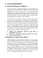
2.1 On-Board Diagnostics (OBD) II
The first generation of On-Board Diagnostics (called OBD I) was
developed by the California Air Resources Board (ARB) and
implemented in 1988 to monitor some of the emission control
components on vehicles. As technology evolved and the desire to
improve the On-Board Diagnostic system increased, a new generation of
On-Board Diagnostic system was developed. This second generation of
On-Board Diagnostic regulations is called "OBD II".
The OBD II system is designed to monitor emission control systems
and key engine components by performing either continuous or
periodic tests of specific components and vehicle conditions. When a
problem is detected, the OBD II system turns on a warning lamp (MIL)
on the vehicle instrument panel to alert the driver typically by the
phrase of “Check Engine” or “Service Engine Soon”. The system will
also store important information about the detected malfunction so that
a technician can accurately find and fix the problem. Here below
follow three pieces of such valuable information:
1) Whether the Malfunction Indicator Light (MIL) is
commanded 'on' or 'off';
2) Which, if any, Diagnostic Trouble Codes (DTCs) are stored;
3) Readiness Monitor status.
2.2 Diagnostic Trouble Codes (DTCs)
OBD II Diagnostic Trouble Codes are codes that are stored by the
on-board computer diagnostic system in response to a problem found
in the vehicle. These codes identify a particular problem area and are
intended to provide you with a guide as to where a fault might be
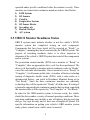
occurring within a vehicle. OBD II Diagnostic Trouble Codes consist
of a five-digit alphanumeric code. The first character, a letter,
identifies which control system sets the code. The other four characters,
all numbers, provide additional information on where the DTC
originated and the operating conditions that caused it to set. Here
below is an example to illustrate the structure of the digits:

3
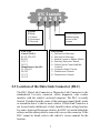
2.3 Location of the Data Link Connector (DLC)
The DLC (Data Link Connector or Diagnostic Link Connector) is the
standardized 16-cavity connector where diagnostic code readers
interface with the vehicle's on-board computer. The DLC is usually
located 12 inches from the center of the instrument panel (dash), under
or around the driver’s side for most vehicles. If Data Link Connector is
not located under dashboard, a label should be there telling location.
For some Asian and European vehicles, the DLC is located behind the
ashtray and the ashtray must be removed to access the connector. If the
DLC cannot be found, refer to the vehicle’s service manual for the
location.
Identifying specific
malfunctioning
section of the
s
y
stems
Systems
B=Body
C=Chassis
P=Powertrain
U=Network
DTC Example
P0202
Code Type
Generic (SAE):
P0, P2, P34-P39
B0, B3
C0, C3
U0, U3.
Manufacturer Specific:
P1, P30-p33
B1, B2
C1, C2
U1, U2
Sub-systems
1= Fuel and Air Metering
2= Fuel and Air Metering
3= Ignition System or Engine Misfire
4= Auxiliary Emission Controls
5= Vehicle Speed Control and Idle
Controls
6= Computer Output Circuits
7= Transmission Controls
8= Transmission Controls

2.4 OBD II Readiness Monitors
An important part of a vehicle’s OBD II system is the Readiness
Monitors, which are indicators used to find out if all of the emissions
components have been evaluated by the OBD II system. They are
running periodic tests on specific systems and components to ensure
that they are performing within allowable limits.
Currently, there are eleven OBD II Readiness Monitors (or I/M
Monitors) defined by the U.S. Environmental Protection Agency
(EPA). Not all monitors are supported by all vehicles and the exact
number of monitors in any vehicle depends on the motor vehicle
manufacturer’s emissions control strategy.
Continuous Monitors -- Some of the vehicle components or systems
are continuously tested by the vehicle’s OBD II system, while others
are tested only under specific vehicle operating conditions. The
continuously monitored components listed below are always ready:
1)Misfire
2)Fuel System
3)Comprehensive Components (CCM)
Once the vehicle is running, the OBD II system is continuously
checking the above components, monitoring key engine sensors,
watching for engine misfire, and monitoring fuel demands.
Non-Continuous Monitors -- Unlike the continuous monitors, many
emissions and engine system components require the vehicle to be
4

5
operated under specific conditions before the monitor is ready. These
monitors are termed non-continuous monitors and are listed below:
1) EGR System
2) O2 Sensors
3) Catalyst
4) Evaporative System
5) O2 Sensor Heater
6) Secondary air
7) Heated Catalyst
8) A/C system
2.5 OBD II Monitor Readiness Status
OBD II systems must indicate whether or not the vehicle’s PCM’s
monitor system has completed testing on each component.
Components that have been tested will be reported as “Ready”, or
“Complete”, meaning they have been tested by the OBD II system. The
purpose of recording readiness status is to allow inspectors to
determine if the vehicle’s OBD II system has tested all the components
and/or systems.
The powertrain control module (PCM) sets a monitor to “Ready” or
“Complete” after an appropriate drive cycle has been performed. The
drive cycle that enables a monitor and sets readiness codes to “Ready”
varies for each individual monitor. Once a monitor is set as “Ready” or
“Complete”, it will remain in this state. A number of factors, including
erasing of diagnostic trouble codes (DTCs) with a code reader or a
disconnected battery, can result in Readiness Monitors being set to
“Not Ready”. Since the three continuous monitors are constantly
evaluating, they will be reported as “Ready” all of the time. If testing of
a particular supported non-continuous monitor has not been completed,
the monitor status will be reported as “Not Complete” or “Not Ready.”
In order for the OBD monitor system to become ready, the vehicle
should be driven under a variety of normal operating conditions. These
operating conditions may include a mix of highway driving and stop
and go, city type driving, and at least one overnight-off period. For
specific information on getting your vehicle’s OBD monitor system
ready, please consult your vehicle owner’s manual.

6
2.6 OBD II Definitions
Powertrain Control Module (PCM) -- OBD II terminology for the
on-board computer that controls engine and drive train.
Malfunction Indicator Light (MIL) -- Malfunction Indicator Light
(Service Engine Soon, Check Engine) is a term used for the light on the
instrument panel. It is to alert the driver and/or the repair technician
that there is a problem with one or more of vehicle's systems and may
cause emissions to exceed federal standards. If the MIL illuminates
with a steady light, it indicates that a problem has been detected and the
vehicle should be serviced as soon as possible. Under certain
conditions, the dashboard light will blink or flash. This indicates a
severe problem and flashing is intended to discourage vehicle
operation. The vehicle onboard diagnostic system can not turn the MIL
off until the necessary repairs are completed or the condition no longer
exists.
DTC -- Diagnostic Trouble Codes (DTC) that identify which section
of the emission control system has malfunctioned.
Enabling Criteria -- Also termed Enabling Conditions. They are the
vehicle-specific events or conditions that must occur within the engine
before the various monitors will set, or run. Some monitors require
the vehicle to follow a prescribed “drive cycle” routine as part of the
enabling criteria. Drive cycles vary among vehicles and for each
monitor in any particular vehicle.
OBD II Drive Cycle -- A specific mode of vehicle operation that
provides conditions required to set all the readiness monitors
applicable to the vehicle to the “ready” condition. The purpose of
completing an OBD II drive cycle is to force the vehicle to run its
onboard diagnostics. Some form of a drive cycle needs to be performed
after DTCs have been erased from the PCM’s memory or after the
battery has been disconnected. Running through a vehicle’s complete
drive cycle will “set” the readiness monitors so that future faults can be
detected. Drive cycles vary depending on the vehicle and the monitor
that needs to be reset. For vehicle specific drive cycle, consult the
vehicle’s Owner’s Manual.

7
Freeze Frame Data -- When an emissions related fault occurs, the
OBD II system not only sets a code but also records a snapshot of the
vehicle operating parameters to help in identifying the problem. This
set of values is referred to as Freeze Frame Data and may include
important engine parameters such as engine RPM, vehicle speed, air
flow, engine load, fuel pressure, fuel trim value, engine coolant
temperature, ignition timing advance, or closed loop status.

3. Using the Code Reader
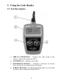
3.1 Tool Description
① OBD II CONNECTOR -- Connects the code reader to the
vehicle’s Data Link Connector (DLC).
② LCD DISPLAY -- Indicates test results.
③ ENTER/EXIT BUTTON -- Confirms a selection (or action)
from a menu list, or returns to previous menu.
④ SCROLL BUTTON -- Scrolls through menu items. It is also used
to enter system setup menu when pressed.
8

9
3.2 Specifications
1) Display: Backlit, 128 x 64 pixel display
2) Operating Temperature: 0 to 60°C (32 to 140 F°)
3) Storage Temperature: -20 to 70°C (-4 to 158 F°)
4) Power: 8 to 18 Volts provided via vehicle battery
5) Dimensions:
Length Width Height
110.3 mm (4.34”) 69.5 mm (2.74”) 20.2 mm (0.80”)
6) 0.18Kg (0.39lb), GW: 0.21Kg (0.46lb)
3.3 Accessories Included
1) User’s Manual -- Instructions on tool operations
2) OBD2 cable -- Provides power to tool and communicates between
tool and vehicle.
3.4 Navigation Characters
Characters used to help navigate the code reader are:
1) “►” -- Indicates current selection.
2) “Pd” -- Identifies a pending DTC when viewing DTCs.
3) “$” -- Identifies the control module number from which the data
is retrieved.
3.5 Vehicle Power
The power of the code reader is provided via the vehicle Data Link
Connector (DLC). Follow the steps below to turn on the code reader:
1) Connect the OBD II cable to the code reader.
2) Find DLC on vehicle.
• A plastic DLC cover may be found for some vehicles and you
need to remove it before plugging the OBD2 cable.
3) Plug OBD II cable to the vehicle’s DLC.

3.6 Product Setup
The code reader allows you to make the following adjustments and
settings:
1) Language: Selects desired language.
2) Unit of measure: Sets the unit of measure to English or Metric.
3) Contrast adjustment: Adjusts the contrast of the LCD display.
• The Settings of the unit will remain until change to the existing
settings is made.
To enter the setup menu
From the second startup screen, press SCROLL button to enter
System Setup menu. Follow the instructions to make adjustments and
settings as described in the following setup options.
10
z The number “x/x” to the upper right corner of the screen
indicates total number of items under the menu and
sequence of currently selected item.
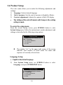
Language Setup
• English is the default language.
1) From System Setup menu, use SCROLL button to select
Language, and press ENTER/EXIT button.
……………….System Setup………… ….
1/4
………………System Setup………… .
1/4
►1) Language
2) Unit of Measure
3) Contrast
4) Exit
► 1) Language
2) Unit of Measure
3) Contrast
4) Exit

2) Use SCROLL button to select the desired language and press
ENTER/EXIT button to save your selection and return to
previous menu.
…………………Language………………….
1/3
► English
Français
Español
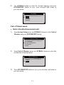
Unit of Measurement
• Metric is the default measurement unit.
1) From System Setup menu, use SCROLL button to select Unit of
Measure and press ENTER/EXIT button.
………………System Setup………… …..
2/4
1) Language
► 2) Unit of Measure
3) Contrast
4) Exit
2) From Unit of Measure menu, use SCROLL button to select the
desired unit of measurement.
………….Unit of Measure……… …….
2/2
English
► Metric
3) Press ENTER/EXIT button to save your selection and return to
previous menu.
11

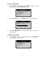
Contrast Adjustment
1) From System Setup menu, use SCROLL button to select
Contrast, and press ENTER/EXIT button.
…………….System Setup………… …….
3/4
1) Language
2) Unit of Measure
►3) Contrast
4) Exit
2) From Contrast menu, use SCROLL button to adjust contrast.
…………….…..Contrast ………………….
Contrast (35%)
12
3) Press ENTER/EXIT button to save your settings and return to
previous menu.
Exiting System Setup
1) Use SCROLL button to select Exit and press ENTER/EXIT
button to return to startup menu.
Use to change
………………System Setup…………… ..
4/4
1) Language
2) Unit of Measure
3) Contrast
► 4) Exit

13
3.7 Vehicle Coverage
ITEM 98568 OBDII/EOBD Code Reader is specially designed to work
with all OBD II compliant vehicles, including those equipped with the
next-generation protocol -- Control Area Network (CAN). It is
required by EPA that all 1996 and newer vehicles (cars and light trucks)
sold in the United States must be OBD II compliant and this includes
all Domestic, Asian and European vehicles.
A small number of 1994 and 1995 model year gasoline vehicles are
OBD II compliant. To verify if a 1994 or 1995 vehicle is OBD II
compliant, check the Vehicle Emissions Control Information (VECI)
Label which is located under the hood or by the radiator of most
vehicles. If the vehicle is OBD II compliant, the label will designate
“OBD II Certified”. Additionally, Government regulations mandate
that all OBD II compliant vehicles must have a “common” sixteen-pin
Data Link Connector (DLC).
For your vehicle to be OBD II compliant it must have a
16-pin DLC
(Data Link Connector) under the dash and the Vehicle Emission
Control Information Label must state that the vehicle is OBD II
compliant.

14
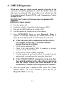
4. OBD II Diagnostics
When more than one vehicle control module is detected by the
scan tool, you will be prompted to select the module where the
data may be retrieved. The most often to be selected are the
Powertrain Control Module [PCM] and Transmission Control
Module [TCM].
CAUTION: Don’t connect or disconnect any test equipment with
ignition on or engine running.
1) Turn the ignition off.
2) Locate the vehicle’s 16-pin Data Link Connector (DLC).
3) Plug into the OBDII cable to the vehicle’s DLC.
4) Turn the ignition on. Engine can be off or running.
5) Press ENTER/EXIT button to enter Diagnostic Menu. A
sequence of messages displaying the OBD2 protocols will be
observed on the display until the vehicle protocol is detected.
If the code reader fails to communicate with the vehicle’s
ECU (Engine Control Unit), a “LINKING ERROR!”
message shows up on the display.
9 Verify that the ignition is ON;
9 Check if the code reader’s OBD II connector is securely
connected to the vehicle’s DLC;
9 Verify that the vehicle is OBD2 compliant;
9 Turn the ignition off and wait for about 10 seconds. Turn the
ignition back to on and repeat the procedure from step 5.
If the “LINKING ERROR” message does not go away, then
there might be problems for the code reader to communicate
with the vehicle. Contact your local distributor or the
manufacturer’s customer service department for assistance.
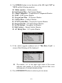
6) After the system status is displayed (MIL status, DTC counts,
Monitor status), wait a few seconds or press any key for
Diagnostic Menu to come up.

……………. System Status…………… …
Codes Found 1
Monitors N/A 4
Monitors OK 3
Monitors INC 3
15
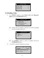
4.1 Reading Codes
1) Use SCROLL button to select Read Codes from Diagnostic
Menu and press ENTER/EXIT button.
.............Diagnostic Menu....... ...
1/6
► 1) Read Codes
2) Erase Codes
3) View Freeze Frame
4) I/M Readiness
z If more than one module is detected, you will be prompted
to select a module before test.
z Use SCROLL button to select a module, and press
ENTER/EXIT button.
2) View DTCs and their definitions on screen.
$11 Pd 1/6
P0115 Generic
………………Control Module……………
1/3
► Engine
Module $A4
Exit
Engine Coolant Temperature
Sensor 1 Circuit

z The control module number, sequence of the DTCs, total
number of codes detected and type of codes (Generic or
Manufacturer specific, Stored or Pending codes) will be
observed on the upper right hand corner of the display.
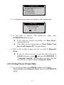
3) If more than one DTC is found, use SCROLL button, as
necessary, until all the codes have been shown up.
z If no codes are detected, a “No codes are stored in the
module!” message displays on the screen.
z If retrieved DTCs contain any manufacturer specific or
enhanced codes, the display indicates “Manufacturer
control”.
$09 4/6
P1324 Other
Manufacturer control
4) Press ENTER/EXIT button to return to previous menu.
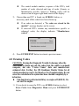
4.2 Erasing Codes
CAUTION: Erasing the Diagnostic Trouble Codes may allow the
code reader to delete not only the codes from the vehicle’s on-board
computer, but also “Freeze Frame” data and manufacturer
enhanced data. Further, the I/M Readiness Monitor Status for all
vehicle monitors is reset to Not Ready or Not Complete status. Do not
erase the codes before the system has been checked completely by a
technician.
z This function is performed with key on engine off (KOEO). Do
not start the engine.
1) If you decide to erase the DTCs, use SCROLL button to select
Erase Codes from Diagnostics Menu and press ENTER/EXIT
button.
16

...........Diagnostic Menu...... ......
2/6
1) Read Codes
►2) Erase Codes
3) Freeze Frame
4) I/M Readiness
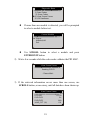
2) A warning message comes up asking for your confirmation.
.............Erase Codes............. ...
Erase trouble codes!
Are you sure?
YES NO
3) If you want to proceed with erasing the codes, press
ENTER/EXIT button to erase.
z If the codes are cleared successfully, an “Erase Done!”
message shows up.
z If the codes are not cleared, then an “Erase Failure. Turn
Key on with Engine off!” message displays.
4) Wait a few seconds or press any key to return to Diagnostic
Menu.
z
If you do wish to proceed to erase the codes, then press
SCROLL button to select NO and press ENTER/EXIT. A
“Command Canceled” message shows up. Press any key
or wait a few seconds to return to Diagnostic Menu.
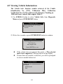
4.3 Viewing Freeze Frame Data
1) To view freeze frame, use SCROLL button to select View
Freeze Frame from Diagnostic Menu and press ENTER/EXIT
button.
17

............Diagnostic Menu...... ....
3/6
1) Read Codes
2) Erase Codes
►3) View Freeze Frame
4) I/M Readiness
z If more than one module is detected, you will be prompted
to select a module before test.
…………….Control Module………… ….
1/3
► Engine
Module $A4
Exit
z Use SCROLL button to select a module and press
ENTER/EXIT button.
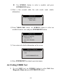
2) Wait a few seconds while the code reader validates the PID MAP.
18
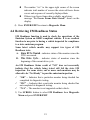
3) If the retrieved information covers more than one screen, use
SCROLL button, as necessary, until all data have been shown up.
…………..View Freeze Frame…… ….
1/4
……………View Freeze Frame…….. .
Reading PID.01
- Please Wait -
DTCFRZF P2770
FUELSYS1 OL
FUELSYS2 N/A
LOAD_PCT (%) 0.0

19
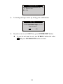
z The number “x/x” to the upper right corner of the screen
indicates total number of screens the retrieved freeze frame
covers and sequence of currently displayed data.
z If there is no freeze frame data available, an advisory
message “No Freeze Frame Data Stored!” shows on the
display.
4) Press ENTER/EXIT to return to Diagnostic Menu.
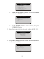
4.4 Retrieving I/M Readiness Status
I/M Readiness function is used to check the operations of the
Emission System on OBD2 compliant vehicles. It is an excellent
function to use prior to having a vehicle inspected for compliance
to a state emissions program.
Some latest vehicle models may support two types of I/M
Readiness tests:
A. Since DTCs Cleared - indicates status of the monitors since the
DTCs are erased.
B. This Drive Cycle - indicates status of monitors since the
beginning of the current drive cycle.
An I/M Readiness Status result of “NO” does not necessarily
indicate that the vehicle being tested will fail the state I/M
inspection. For some states, one or more such monitors may be
allowed to be “Not Ready” to pass the emissions inspection.
9 “OK” -- Indicates that a particular monitor being checked has
completed its diagnostic testing.
9 “INC” -- Indicates that a particular monitor being checked has
not completed its diagnostic testing.
9 “N/A” -- The monitor is not supported on that vehicle.
1) Use SCROLL button to select I/M Readiness from Diagnostic
Menu and press ENTER/EXIT.
Page is loading ...
Page is loading ...
Page is loading ...
Page is loading ...
Page is loading ...
Page is loading ...
-
 1
1
-
 2
2
-
 3
3
-
 4
4
-
 5
5
-
 6
6
-
 7
7
-
 8
8
-
 9
9
-
 10
10
-
 11
11
-
 12
12
-
 13
13
-
 14
14
-
 15
15
-
 16
16
-
 17
17
-
 18
18
-
 19
19
-
 20
20
-
 21
21
-
 22
22
-
 23
23
-
 24
24
-
 25
25
-
 26
26


Ask a question and I''ll find the answer in the document
Finding information in a document is now easier with AI
Related papers
Other documents
-
 TT TOPDON al200 User manual
-
 SP tools SP61150 OBDII/EOBD Scanner Code Reader User manual
-
Innova OBD2 Owner's manual
-
CEN-TECH 99722 User manual
-
-
 Zurich Item 63807 Owner's manual
-
Zurich 63806 Owner's manual
-
 Zurich 63809 Owner's manual
-
Autel Autel AL519 User manual
-
 Performance Tool W2976 User manual


