Page is loading ...

INSTRUCTION MANUAL Ver 1.0
(3810-0132D)
Indoor Mini Speed Dome Camera Series
www.ernitec.com

Indoor Mini Speed Dome Camera
This lightning flash with arrowhead symbol is intended to alert the user to the
presence of un-insulated "dangerous voltage" within the product's enclosure that may
be of sufficient magnitude to constitute a risk of electric shock to persons.
This exclamation point symbol is intended to alert the user to the presence of
important operating and maintenance (servicing) instructions in the literature
accompanying the appliance.
Important Safeguard
1. Read Instructions
Read all of the safety and operating instructions before using the product.
2. Retain Instructions
Save these instructions for future reference.
3. Attachments/Accessories
Do not use attachments or accessories unless recommended by the appliance manufacturer as they may cause
hazards, damage product and void warranty.
4. Water and Moisture
Do not use this product near water or moisture.
5. Installation
Do not place or mount this product in or on an unstable or improperly supported location. Improperly installed
product may fall, causing serious injury to a child or adult, and damage to the product. Use only with a mounting
device recommended by the manufacturer, or sold with the product. To insure proper mounting, follow the
manufacturer's instructions and use only mounting accessories recommended by manufacturer.
6. Power source
This product should be operated only from the type of power source indicated on the marking label.
2
www.ernitec.com

Indoor Mini Speed Dome Camera
NOTICE
Precautions
■ Operating
z Before using, make sure power supply and others are properly connected.
z While operating, if any abnormal condition or malfunction is observed, stop using the camera immediately
and then contact your local dealer.
■ Handling
z Do not disassemble or tamper with parts inside the camera.
z Do not drop or subject the camera to shock and vibration as this can damage camera.
z Care must be taken when you clean the clear dome cover. Especially, scratch and dust will ruin your
quality of camera.
■ Installation and Storage
z Do not install the camera in areas of extreme temperature, which exceed the allowable range.
z Avoid installing in humid or dusty places.
z Avoid installing in places where radiation is present.
z Avoid installing in places where there are strong magnetic fields and electric signals.
z Avoid installing in places where the camera would be subject to strong vibrations.
z Never expose the camera to rain and water.
1. Introduction
Features 5
Product & Accessories ……………………….………………………………………………………………………. 7
Parts Name & Functions ..…………………….……………………………………………………………………… 8
2. Installation
DIP Switch Setup ……………………………………………………………………………………………………… 9
Direct Installation on the Ceiling …………………………………………………………………………………… 11
Installation using Pendant Mount Bracket .....…………………………………………………………………….. 12
Installation using Wall Mount Bracket ……………………………………………………………………………… 13
Cabling ………………………………………………………………………………………………………………… 15
3. Operation
Check points before Operation …………………………………………………………………………………….. 18
Preset and Pattern Function Pre-Check …………………………………………………………………………… 18
Starting OSD Menu …………………………………………………………………………………………………… 19
Reserved Preset ………………………………………………………………………………………………………. 19
Preset ………………………………………………………………………………………………………………...... 19
Swing ………………………………………………………………………………………………………………...... 20
Pattern ..……………………………………………………………………………………………………………...... 21
Group ………………………………………………………………………………………………………………...... 22
3
www.ernitec.com

Indoor Mini Speed Dome Camera
CONTENTS
Other Functions …..………………………………………………………………………………………………...... 23
OSD Display of Main Screen ……………………………………………………………………………………...... 24
4. Menu
General Rules of Key operation for Menu .……………………………………………………………………...... 25
Main Menu ………………………………….……………………………………………………………………....... 25
Display Setup .……………………………….……………………………………………………………………...... 26
Privacy Zone Mask Setup .................…….……………………………………………………………………...... 27
Zoom Camera Setup .……………………….……………………………………………………………………...... 28
Motion Setup .……………………………….……………………………………………………………………...... 30
Preset Setup 32
Swing Setup ………………………………….……………………………………………………………………...... 34
Pattern Setup .……………………………….……………………………………………………………………....... 35
Group Setup ..……………………………….……………………………………………………………………....... 36
System Initialize …………………………….……………………………………………………………………....... 38
5. Specifications
x10 Zoom Model ..............………………….……………………………………………………………………...... 39
Dimension ..………………………………….……………………………………………………………………...... 40
Features
Camera Specifications
z CCD Sensor : 1/4" Interline Transfer CCD
z Zoom Magnification : x10 Optical Zoom, x10 Digital Zoom (Max. ×100 Zoom) Æ x10 Zoom Model
z Day & Night Function
z Various Focus Mode : Auto-Focus / Manual Focus / Semi-Auto Focus.
z Independent & Simultaneous Camera Characteristic Setup in Preset operation
Powerful Pan/Tilt Functions
z Max. 360°/sec high speed Pan/Tilt Motion
z Using Vector Drive Technology, Pan/Tilt motions are accomplished in a shortest path. As a result, time to
target view is reduced dramatically and the video on the monitor is very natural to watch.
z For jog operation using a controller, since ultra slow speed 0.05°/sec can be reached, it is very easy to locate
camera to desired target view. Additionally it is easy to move camera to a desired position with zoom-
proportional pan/tilt movement.
4
www.ernitec.com

Indoor Mini Speed Dome Camera
1. INTRODUCTION
Preset, Pattern, Swing, Group, Privacy Mask and More…
z Max. 127 Presets are assignable and characteristics of each preset can be set up independently, such as
White Balance, Auto Exposure, Label and so on.
z Max. 8 set of Swing action can be stored. This enables to move camera repetitively between two preset
positions with designated speed.
z Max. 4 of Patterns can be recorded and played back. This enables to move camera to follow any trajectory
operated by joystick as closely as possible.
z Max. 8 set of Group action can be stored. This enables to move camera repetitively with combination of
Preset or Pattern or Swing. A Group is composed of max. 20 entities of Preset/Pattern/Swings.
z Privacy Masks are assignable, not to intrude on other’s privacy. (4 Privacy Zones)
PTZ(Pan/Tilt/Zoom) Control
z With RS-485 communication, max. 255 of cameras can be controlled at the same time.
z Pelco-D or Pelco-P protocol can be selected as a control protocol in the current version of firmware.
OSD(On Screen Display) Menu
z OSD menu is provided to display the status of camera and to configure the functions interactively.
z The information such as Camera ID, Pan/Tilt Angle, Alarm Input and Preset can be displayed on screen.
Alarm I/O Functions
z 4 alarm sensor Inputs are available.
z To reject external electric noise and shock perfectly, alarm sensor Input is decoupled with photo coupler.
z The signal range of sensor input is from DC 5.0 to 12.0 volts to adopt various applications.
z If an external sensor is activated, camera can be set to move to the corresponding Preset position.
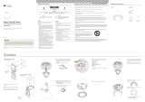
Product & Accessories
5
www.ernitec.com

Indoor Mini Speed Dome Camera
1. INTRODUCTION
Product & Accessories
Options
● Pendant Mount Bracket ● Wall Mount Bracket
Parts Name & Functions
6
www.ernitec.com

Indoor Mini Speed Dome Camera
1. INTRODUCTION
z Main Unit / Surface Mount Bracket z Back of Main Unit
z Bubble Do not detach protection vinyl from the bubble before finishing all installation
process to protect the bubble from scratches or dust.
z Surface Mount Bracket This is used to install the camera directly on the ceiling. After separating this
cover first and then attach this directly to ceiling. Camera must be assembled at
the last stage.
z Fixing Screw Fixes main unit to surface mount bracket.
z Cabling Terminal Block During installation, Power, Video, Communication, Alarm Input cables are
connected on to this cabling terminal block.
z DIP Switch Adjusts camera ID and protocols.
DIP Switch Setup
Before you install the camera, you should set the DIP switches to configure the camera ID, communication protocol.
7
www.ernitec.com

Indoor Mini Speed Dome Camera
2. INSTALLATION
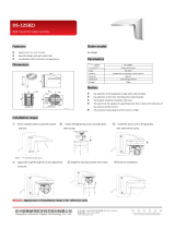
Camera ID Setup
z ID number of camera is set using dip switch. The example is shown
bellow.
Pin 1 2 3 4 5 6 7 8
ID Value 1 2 4 8 16 32 64 128
ex) ID=5 on off on off off off off off
ex) ID=10 off on off on off off off off
Do not use 0 as camera IDz The range of ID is 1~255. . Factory default of
Camera ID is 1.
z If you want to control a certain camera, you must match the camera ID
with Cam ID setting of DVR or Controller.
Communication Protocol Setup
8
www.ernitec.com

Indoor Mini Speed Dome Camera
2. INSTALLAT2. INSTALLATION ION
z Select the appropriate Protocol with DIP switch combination.
Switch State
P0
(Pin 1)
Protocol
P3
P1
(Pin 2)
(Pin 3)
OFF OFF OFF PELCO-D, 2400 bps
ON OFF OFF PELCO-D, 9600 bps
OFF ON OFF PELCO-P, 4800 bps
ON ON 0FF PELCO-P, 9600 bps
Others Reserved
z If you want to control using DVR or P/T controller, their protocol must be
identical to camera. Otherwise, you can not control the camera.
z If you changed camera protocol by changing DIP S/W, the change will be
effective after you reboot the camera.
z Factory default of protocol is “Pelco-D, 2400 bps”.
Termination Switch Setting
Termination switch(Pin 4) is used in cases listed below.
z Long-distance communication between the controller and the camera
(1-to-1 connection)
When the connecting distance between the two units is especially long,
communication errors may occur due to the impedance of transmission
cable. In this case, set the termination switch of both units to ON.
z Controlling multiple cameras (Multiple connection)
The camera may not operate correctly if multiple cameras are connected
and controlled. In this case, set the termination switch of the controller and
the last connected camera to ON and the switch of other cameras is OFF.
Ex) Using the Terminating Resistance
Direct Installation on the Ceiling
9
www.ernitec.com

Indoor Mini Speed Dome Camera
To pass cables to upside of ceiling, please, make about
50~60mm hole on the ceiling panel.
Detach the marked part from the rubber gasket and
srew the surface mount bracket to the ceiling with
fixing screws.
You can use “Guide Pattern” for
the making holes.
Wire cables to terminal block and connect the terminal
blocks to main unit.
Insert the main body into the surface mount bracket
with the molding lines on each part being aligned
and turning clockwise.
Insert the fixing screw tightly and detach the protection
vinyl from dome cover.
Installation using Pendant Mount Bracket
10
www.ernitec.com

Indoor Mini Speed Dome Camera
2. INSTALLATION
Screw pendant mount to ceiling with screws. Detach the marked part from the rubber gasket and
screw the mounting base to the pendant mount
bracket with fixing screws.
You can use “Guide Pattern” for
the making holes.
Wire cables to terminal block and connect the terminal
blocks to main unit.
Insert the main body into the pendant mount bracket
with the molding lines on each part being aligned
and turning clockwise.
11
www.ernitec.com

Indoor Mini Speed Dome Camera
2. INSTALLATION
Insert the fixing screw tightly and detach the
protection vinyl from dome cover.
Installation using Wall Mount Bracket
Screw wall mount bracket to wall with 3 screws. Detach the marked part from the rubber gasket and
srew the mounting base to the wall mount bracket with
fixing screws.
You can use “Guide Pattern" for
the
12
www.ernitec.com

Indoor Mini Speed Dome Camera
2. INSTALLATION 2. INSTALLATION
Wire cables to terminal block and connect the terminal
blocks to main unit.
Insert the main body into the wall mount bracket with
the molding lines on each part being aligned and
turning clockwise.
Insert the fixing screw tightly and detach the protection
vinyl from dome cover.
Cabling
13
www.ernitec.com

Indoor Mini Speed Dome Camera
Power Connection
z Please, check the voltage and current capacity of rated power carefully. Rated power is indicated in the back
of main unit.
Rated Power Input Voltage Range Current Consumption
DC 12V DC 11V ~ 18V 1 A
AC 24V AC 17V ~ 29V 0.8 A
RS-485 Communication
z For PTZ control, connect this line to keyboard and DVR. To control multiple cameras at the same time, RS-
485 communication lines of them is connected in parallel as shown below.
14
www.ernitec.com

Indoor Mini Speed Dome Camera
2. INSTALLATION
Audio Input/Output Connection (Reserved for network model)
z Connection with audio input/output device.
Video Connection
z Connect with BNC coaxial cable
Network Connection (Reserved for network model)
Notice) Network model is now preparing.
z NETWORK 1
Connect with LAN cable.
If LAN cable is not connected properly, This product can not be operate.
z NETWORK 2 (Reserved for supplier.)
DO NOT CONNECTED ANY DEVICE.
15
www.ernitec.com

Indoor Mini Speed Dome Camera
2. INSTALLATION
Alarm Input Connection
z Sensor Input
IN COM+
Internal
+5V~12V
IN 1-
IN 4-
Sensor 1 Output
+
+
-
-
+
-
Sensor 4 Output
Before connecting sensors, check driving voltage and output signal type of the sensor. Since output signal types of
the sensors are divided into Open Collector and Voltage Output type in general, the cabling must be done properly
after considering these typed.
Signal Description
IN COM+ Connect (+) cable of electric power source for Sensors to this port as
shown in the circuit above.
IN1-, IN2-, IN3-, IN4- Connect output of sensors for each port as shown in the circuit above.
If you want to use Alarm Input, the types of sensor must be selected in OSD menu. The sensor types are Normal
Open and Normal. If sensor type is not selected properly, the alarm can be activated reversely.
Normal Open Output Voltage is high state when sensor is activated
Normal Close Output Voltage is high state when sensor is not activated
16
www.ernitec.com

Indoor Mini Speed Dome Camera
3. OPERATION
Check points before operation
z Before power is applied, please check the cables carefully.
z The camera ID of the controller must be identical to that of the target camera. The camera ID can be checked
by reading DIP switch of the camera.
z If your controller supports multi-protocols, the protocol must be changed to match to that of the camera.
z If you changed camera protocol by changing DIP switch, the change will be effective after you reboot the
camera.
z Since the operation method can be different for each controller available, refer to the manual for your controller
if camera can not be controlled properly. The operation of this manual is based on the standard Pelco
®
Controller.
Preset and Pattern Function Pre-Check
z Check how to operate preset and pattern function with controller or DVR in advance to operate camera function
fully when using controller or DVR.
z Refer to the following table when using standard Pelco® protocol controller.
<Go Preset> Input [Preset Number] and press [Preset] button shortly.
Input [Preset Number] and press [Preset] button for more than 2 seconds.
<Set Preset>
<Run Pattern> Input [Pattern Number] and press [Pattern] button shortly.
<Set Pattern> Input [Pattern Number] and press [Pattern] button for more than 2 seconds.
z If controller or DVR has no pattern button or function, use shortcut keys with preset numbers. For more
information, refer to “Reserved Preset” in this manual.
17
www.ernitec.com

Indoor Mini Speed Dome Camera
3. OPERATION
Starting OSD Menu
z Function Using the OSD menu, Preset, Pattern, Swing, Group and Alarm Input function can be
configured for each application.
z Enter Menu <Go Preset> [95]
Reserved Preset
Some Preset numbers are reserved to special functions. z Description
z Function <Go Preset> [95] Enters into OSD menu.
<Go Preset> [131~134] Runs Pattern Function 1 ~ 4
<Go Preset> [141~148] Runs Swing Function 1 ~ 8
<Go Preset> [151~158] Runs Group Function 1 ~ 8
Preset
z Function Max. 127 positions can be stored as Preset position. The Preset number can be assigned
from 1 to 128, but 95 is reserved for starting OSD menu.
Camera characteristics (i.e. White Balance, Auto Exposure) can be set up independently for
each preset. Label should be blank and "Camera Adjust" should be set to "GLOBAL" as
default. All characteristics can be set up in OSD menu.
z Set Preset <Set Preset> [1~128]
z Run Preset <Go Preset> [1~128]
To delete Preset, use OSD menu. z Delete Preset
18
www.ernitec.com

Indoor Mini Speed Dome Camera
3. OPERATION
Swing
z Function
By using Swing function, you can make camera to move between 2 Preset positions
repeatedly. When swing function runs, camera moves from the preset assigned as the 1st
point to the preset assigned as the 2nd point in CW(Clockwise) direction. Then camera
moves from the preset assigned as the 2nd point to the preset assigned as the 1st point in
CCW(Counterclockwise) direction.
In case that the preset assigned as the 1st point is same as the preset assigned as the 2nd
point, camera turns on its axis by 360° in CW(Clockwise) direction and then it turns on its
axis by 360° in CCW(Counterclockwise) direction. Speed can be set up from 1°/sec to
180°/sec.
To set Swing, use OSD menu.
z Set Swing
z Run Swing Method 1) <Run Pattern> [Swing NO.+10] ex) Run Swing 3 : <Run Pattern> [13]
Method 2) <Go Preset> [Swing NO + 140] ex) Run Swing 3 : <Go Preset>[143]
To delete Swing, use OSD menu. z Delete Swing
19
www.ernitec.com

Indoor Mini Speed Dome Camera
3. OPERATION
Pattern
z Function Pattern Function is that a camera memorizes the path (mostly curve path) by joystick of
controller for assigned time and revives the path exactly as it memorized.
4 Patterns are available and Maximum 1200 communication commands can be stored in
a pattern.
Pattern can be created by one of following two methods.
z Set Pattern
Method 1) <Set Pattern> [Pattern NO.]
z Pattern editing screen is displayed as bellow.
z Movement by Joystick and preset movement can be memorized in a pattern.
z The rest memory size is displayed in progress bar.
z To save the recording, press NEAR key and to cancel, press FAR key.
Method 2) OSD Using OSD Menu: See the section “How to use OSD Menu”.
Method 1) <Run Pattern> [Pattern NO.] ex) Run Pattern 2 : <Run Pattern> [2]
z Run Pattern
Method 2) <Go Preset> [Pattern NO+130] ex) Run Pattern 2 : <Go Preset>[132]
To delete Pattern, use OSD menu.
z Delete Pattern
20
www.ernitec.com
/