ETC Source Four LED Series Assembly Instructions Manual

Type
Assembly Instructions Manual

ETC Source Four LED Series offers exceptional color quality, precise framing, and a vast array of lens tubes, providing endless possibilities for shaping light and creating stunning effects. Its advanced LED technology ensures consistent output and color temperature, while the innovative design allows for quick and easy setup. With its versatility and reliability, the ETC Source Four LED Series is the perfect choice for any professional lighting application.

ETC Source Four LED Series offers exceptional color quality, precise framing, and a vast array of lens tubes, providing endless possibilities for shaping light and creating stunning effects. Its advanced LED technology ensures consistent output and color temperature, while the innovative design allows for quick and easy setup. With its versatility and reliability, the ETC Source Four LED Series is the perfect choice for any professional lighting application.

Parts List and
Assembly Instructions
S O U R C E F O U R
2
Final assembly
Reference Part Description Quantity
Number Number Required
1 7060A2008 Lamp socket assembly 1
2 7060A2011 Reflector housing assembly, single clutch 1
2A 7060A2020 Reflector housing assembly, double clutch 1
3 7060A2012 Front barrel assembly 1
4 7060A2000-K 5° lens tube, with knob 1
5 7060A2001-K 10° lens tube, with knob 1
6 7060A2002-K 19° lens tube (6 x 16), with knob 1
7 7060A2003-K 26° lens tube (6 x 12), with knob 1
8 7060A2004-K 36° lens tube (6 x 9), with knob 1
9 7060A2005-K 50° lens tube (4.5 x 6), with knob 1
10 7060A4008-01 Knob set with male insert 2
11 HW5143 Washer, flat fiber 1
Optional equipment
12 HW5197 Screw, 1/4-20 x 5/8, black zinc 1
3
1
2
2A
11
10
(2 required)
4
5
6
7
8
9
12
10
2/96
3
Lamp socket assembly
Reference Part Description Quantity
Number Number Required
1 7060A3055 Housing, socket, casting, painted 1
2 7060A3057 Socket, light baffle casting, painted 1
3 7060A4007 Knob, X-Y, lamp set 1
4 7060A4008-02 Knob, Z, lamp set w/female insert 1
5 7060A4011 Bushing, cup 1
6 7060A3011 Hub, index, casting 1
7 7060A3012 Spring, lamp retainer 1
8 HW748 Spring, compression 1
9-11 M706 Complete TP22 CLCM assembly 1
9 W330-03 TP22 CLCM assembly, mica (1)
10 W330-01 TP22 CLCM 16-gauge, 1/4" semi-striped, Ni-gold contacts,
600V, 250˚C (2)
11 W330-02 TP22 CLCM assembly, ceramic (1)
12 HW534 Nut, hex, 1/4-20, black zinc 1
13 7060A3025 Screw, 1/4-20 knurled head 1
14 HW746 Retaining ring, flat, Southco 1
15 HW5123 Nut, hex, 9/16-18, black zinc 1
16 HW747 Washer, wave 1
17 7060A3056 Clamp, strain relief, painted 1
18 HW3103 Screw, 8-32 x 5/8 PhFHMS, black zinc 2
19 HW5122 Bolt, 1/4-20 x 1.75, full thread, black zinc 1
20 HW2125 Screw, self tap, 6-32 x 1/4, black zinc 1
21 7060A7003 48" W420 wire, 16 gauge, 200° C/300V, green
UL 1180/CSA AWM with lug J490T installed 1
22 W689 36" sleeve, fiberglass (not pictured) 1
23 HW749 Spring, ground 1
24 7060A7007 4" W420 wire, 16 gauge, 200° C/300V, green,
UL 1180/CSA AWM with two J490T lugs installed 1
20
6
1
24
23
17
18
(2 required)
13
4
15
16
3
5
2
21
11
24
9
8
7
10
(2 required)
12
14
19
2/96
4
Lamp socket assembly
Tools required: Open-end adjustable wrench or a 7/16" socket, needle-nose pliers, screwdriver.
1. Insert the bolt (19) through the light baffle socket casting (2), then place green ground wire assemblies
(21 and 24) on the end of the bolt protruding through the back of the casting. Place the ground wires
through the indent in the lip surrounding the bolt hole in the casting. Secure with nut (12) and torque to
60 inch pounds.
2. Place the ceramic TP22 socket (11) into the light baffle socket casting (2) as shown. (Be sure it is well
seated.) Firmly push the connectors on the white TP22leads (10) into the grooves in the socket.
3. Place the TP22 mica (9) over the leads, then install the lamp retainer spring (7).(The lamp retainer spring
will secure the mica.) Insert the spring one end at a time, making sure the rectangular slot in each side of
the spring seats on the corresponding tab in the light baffle socket casting.
Important: If the spring does not seat correctly, it may be necessary to“coax” it into place. Use a
screwdriver or needle-nose pliers for this.
1
24
14
23
13
4. Assemble the index hub (6) and bushing
cup (5) as shown (the tab on the bushing
cup must be to the side). Insert the
threaded end of the index hub through the
back of the housing socket casting (1).
5. Slide the X-Y knob (3) over the exposed
index hub bolt (6), then insert the wave
washer (16) on the bolt and secure with the
9/16 hex nut (15). Tighten the X-Y knob (3)
all the way to the right.
Note: The wave washer must be installed
with the upward curve toward the hex nut.
6. Insert the knurled head screw (13) through
the housing socket casting (1). Attach the
lug of the shorter green ground wire (24)
and the ground spring (23) and secure with
the Southco flat retaining ring.
Note: Use pliers to straighten the Southco
retaining ring (14) if it bends when you
install it on the bolt.
1
5
3
16
15
4
6
5
1
21
17
22
10
Cable clamp
Fiberglass sleeving with TP22 leads
24
10
Socket housing
Ground lead
TP22 contact lead
TP22 contact lead
Ground lead
Wire lead routing diagram
7. Lay the leads in the bottom half of the cable clamp, making sure that the fiberglass sleeving extends
slightly past the screw holes in the housing socket casting, (install new sleeving if necessary) then route
the wires as shown.
Important: You must follow the wire routing diagram to ensure that the socket leads do not interfere
with the lamp focus mechanism.
8. Install the top half of the cable clamp (17) and secure it with the two screws (18). Tighten the screws
alternately to ensure a solid connection.
Note: To ensure that the clamp holds the cable tightly, flatten the cable, then twist it a half turn
before you install the top half of the clamp. Make sure the top edge of the cable clamp is even with
the edge of the socket to prevent interference with lamp focus movement. Make sure sleeving is not
pinched.
9. Place the spring (8) on the protrusion on the inside of the index hub.
10. Join the two castings, making sure that the wires still conform to the wire routing diagram and are not
pinched between the two pieces.
11. Before proceeding, check again to make sure the green and white wires are still positioned as indicated
in the wire lead routing diagram. Adjust if necessary.
12. Press the two castings together firmly so the bottom of the light baffle (2) sits on top of the cable clamp
(17), then install the Z lamp knob (4). Hand tighten the knob all the way to the right.
Important: You must install Z knob as described above to ensure proper lamp focus travel.
6
SOURCE FOUR
UL
Reflector housing assembly
Reference Part Description Quantity
Number Number Required
1 7060A3054 Housing, reflector casting, single clutch, painted 1
1A 7060A30XX Housing, reflector casting, double clutch, painted
2 7060A3006 Clip, reflector retainer 4
3 7060A4010 Bushing, gate 4
4 7060A3016 Plate, clutch 1 (2 for 1A)
5 7060A3019 Spring, reflector support 1
6 7060A4015 Reflector, molded glass, coated 1
7 7060A3058 Bracket, yoke, painted 1
8 HW8144 Handle, yoke knob, 5/16 - 18 1 (2 for 1A)
9 HW753 Rivet, machine, 3/16 x .720, flat head, black zinc 2 (4 for 1A)
10 HW5126 Washer, flat, 5/16, black zinc 3
11 HW5193 Bolt, hex, 5/16-18 x 3/4, black zinc 2
12 HW5125 Bolt, carriage, 5/16-18 x .75, black zinc 1 (2 for 1A)
13 HW752 Rivet machine, 3/16 x 5/16, black zinc 4
Optional equipment
HW5127 Nut, hex 5/16-18 (can be used with (11) hex bolt)
1
10
(3 required)
11
(2 required)
9
(2 required)
4
8
5
3
(4 required)
12
7
6
2/96
1A
2 (4 required)
13 (4 required)
7
To remove a reflector
Tools required: Two spare reflector retainer clips (2).
1. Wedge one arm of a spare retainer clip between the lip of one of the installed clips
and the rim of the reflector, then slide the arm down between the installed clip and
the reflector as shown in figure 1.
2. Insert the other arm of the spare clip between the other arm of the installed clip and
the reflector, as shown in figure 2.
Warning: Do not slide the spare clip all the way in or it will be very difficult to
remove…leave at least a quarter inch exposed.
3. Now slide the entire clip between the reflector and the installed clip as shown in
figure 3. Remember, do not slide it all the way in.
4. Repeat this procedure with the second spare clip, inserting it between an adjacent
installed clip and the reflector.
5. Turn the reflector housing casting over, so that the rear of the reflector is in view. Gently push on the
reflector, toward the side of the housing where the extra clips were placed. The reflector will slip off to
the side at an angle.
6. Turn the reflector housing casting back over and gently slide the reflector out from under the retaining
clips.
To install a reflector
Note: The following assumes all four reflector retainer clips (2) have already been riveted to the reflector
housing casting (1) and the gate bushings (3) installed on the retainer clips.
1. Place the reflector housing casting (1) on a flat work surface with the large opening facing up.
2. Install the reflector support spring (5) in the circular opening at the base of the casting.
3. Insert the reflector (6) at an angle, under any three legs of the reflector's clips.
4. Gently press down on the reflector until it snaps into place under the clips.
Note: If the reflector does not snap in, turn the casting over. Gently pull on the side of the reflector that
has not snapped in until the rest of the reflector slides into place.
To clean the reflector
Remove dust with a blast of oil-free air or wipe with a clean, lint-free cloth using alcohol or distilled water
(alcohol is recommended).
Warning: Do not use glass and window cleaners on the reflector. Chemicals in these cleaners will stain
the reflector.
figure 2
figure 1
figure 3
8
Front barrel assembly
Reference Part Description Quantity
Number Number Required
1 7060A3052 Front barrel, top casting, painted 1
2 7060A3053 Front barrel, bottom casting, painted 1
3 7060A2025 Shutter blade assembly, 22 gauge 4
4 7060A3001-01 Plate, divider with dimples (bottom) 1
5 7060A3003 Plate, gate (middle) 1
6 7060A3001-02 Plate, divider (top) 1
7 HW754 Shutter spring 4
8 HW370 Nut, Ny-lok, 8/32, black zinc 4
9 HW391 Screw, PHMS, 8/32 x 3/4, black zinc 4
10 7060A3045 Cover, iris slot 1
11 HW2137 Screw, 6-32 x 1/4, black zinc 2
Note: The bottom divider plate (4)
has four dimples punched into the
surface; the top plate (6) has none.
The middle divider plate (5) is
noticeably thinner-gauge metal
than the other two.
(See detail to the right)
4
6
5
3
(4 required)
7
(4 required)
2
8
(4 required)
9
(4 required)
10
11
(2 required)
1
3
4
5
6
2/96
2/96
9
Front barrel assembly
Tools required: Phillips head screwdriver.
1. Stand the top and bottom front barrel castings (1 and 2) upright with the shutter openings down.
Note: The top front barrel casting contains the iris slot.
2. Slide in the bottom divider plate (4). The dimples on the divider plate must point down.
Note: The notches on the divider plates must fit snugly against the flanges in the casting so the plates
do not move.
Warning: Divider plate edges are sharp. Handle with caution!
3. With the bottom barrel to your left, place two shutter blades (3) on top of dimple plate (4), handles facing
outward, up and down.
Note: Install shutter blades with the rounded side facing up toward the front of the casting.
4. Place the middle divider plate (5) on top of the two shutter blades.
5. Place the two remaining shutter blades on top of the middle divider plate. Pull the blade and plate
assembly slightly forward to allow the handle to slip through the slot in the bottom casting.
Note: The third and fourth shutter blades should be at 90˚ angles to the first and second.
6. Place the top divider plate (6) on top of the third and fourth shutter blades.
Note: Make sure no shutter assembly components are under the pattern holder guides.
7. With both front barrel castings still standing upright, join the two halves, sliding the handle of the top
shutter blade through the slot in the top front barrel casting (1).
8. Starting at the bottom of the castings (closest to the shutters), use four PHMS screws (9) and Ny-lok
nuts (8) to fasten the front barrel casting halves together, as shown. Hold the Ny-lok nuts tight against
the casting while tightening the screws. Torque the screws to 25 inch/pounds.
Note: The tops of the two front barrel castings must be even. Adjust as necessary before completely
tightening the nuts and screws. Failure to do this could interfere with the barrel rotation.
9. Turn the front barrel assembly over so that the narrower end is on your work surface.
10. Install the four shutter springs (7) between the four dimples in the shutter plate and the tabs in the lip of
the casting.
Note: Install the springs at the joints in the castings on either of the tabs at the joint. Once they are
installed, the springs at the joints will sit at a slight angle.
Caution: During assembly, the shutter springs can pop out of place. Always wear protective eyewear
during this procedure.
11. Place iris slot cover (10) over the iris slot. Use two screws (11) to secure the cover.
10
19° (6x16)
Red dot
26° (6x12)
Black dot
50° (4.5x6)
Yellow dot
36° (6x9)
No dots
Place side of lens
with painted dot
toward front of
fixture.
Note: Each lens is different.
Do not interchange. i.e., do not
place a 19° lens in a 26° slot.
3
(4 required)
8A
1
10
9
12
(4 required)
4
(4 required for 19°, 26°, 50° lens)
(8 required for 36° lens set)
5
6
7
8
11
(4 required)
13
2
19°, 26°, 36°, and 50° lens tubes
Reference Part Description Quantity
Number Number Required
1 7060A3050 Lens holder, left casting, painted 1
2 7060A3051 Lens holder, right casting, painted 1
3 7060A4009 Bushing, guide 4
4 7060A4012 Pad lens support - asphere 4
Pad lens support - meniscus set 8
5 7060A4002 Aspheric lens, 19° 1
6 7060A4001 Aspheric lens, 26° 1
7 7060A4004 Aspheric lens, 50° 1
8 7060A4020 Meniscus lens, 36° set, front 1
8A 7060A4021 Bi-convex lens, 36° set, rear 1
9 7060A3079 Clip, gel retainer, 90° bend 1
10 HW750 Spring, retainer 1
11 HW391 Screw, PHMS, 8-32 x 3/4, black zinc 4
12 HW370 Nut, Ny-Lok, 8/32, black zinc 4
13 HW534 Nut, hex, 1/4-20, black zinc 1
14 7060A4033 19° lens tube label 1
15 7060A4034 26° lens tube label 1
16 7060A4035 36° lens tube label 1
17 7060A4036 50° lens tube label 1
14,15,16,17
2/96
11
19°, 26°, 36°, and 50° lens tube assembly
Tools required: Phillips head screwdriver.
1. Place the left and right lens holder castings (1 and 2) face up
on your work surface with the colorframe grooves to your left.
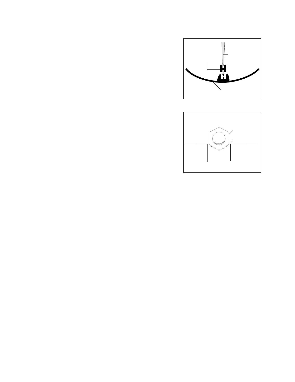
2. Install lens support pads (4) as required inside both lens holder
castings. Four pads are required per lens.
Note: Pads must be inserted short side down as shown.
3. Install the 1/4-20 hex nut (13) in the left lens holder casting as
shown.
4. Install the short end of the gel retainer clip (9) in the left lens
holder casting (1).
5. Position the clip in the forward, locked position, then install
the retainer spring (10) on the clip.
6. Install the required lens (or lenses) (5,6,7, 8 or 8A) as shown
on page 10.
Note: 19°, 26° and 50° aspheric lenses have painted dots to
orient the lens in the tube. Install the lens with the painted dot
facing the front of the tube. Seat the lens in the support pads
so the dot remains visible.
36° lens set: Install the meniscus lens (8) in the 26° position, with the convex side of the lens facing the
front of the lens tube. Place the biconvex lens (8A) in the last slot in the tube, with the flat side facing
the rear of the lens holder.
Do not use the slot marked 36°
7. Fit the clip (9) and spring (10) into the right lens casting (2). Gently place the right lens casting onto the
left lens casting, making sure that the 1/4-20 hex nut and retaining clip assembly stay properly seated.
Note: Look into the lens holder while placing the castings together. Make sure the lens stays straight
and that the top edge seats properly into the support pads.
8. Install the PHMS screws (11) and Ny-lok nuts (12) in four locations. Hold the nuts tight against the
casting and torque the screws to 25 inch pounds.
9. Install the six bushing guides (3). Point the narrow tab on the bottom toward the back of the casting;
point the square tab toward the front. Squeeze the guides slightly so they bend in the middle then snap
into place.
Note: If there is a curve in the top of the guide, install the guide so that the flat portion is towards the
back of the tube.
Cleaning 19°, 26°, 36°, and 50° glass lenses
1. Dampen a clean, lint-free cloth with vinegar or household ammonia. You may use water, but it will leave
spots which may be removed by polishing the lens gently with a clean, dry cloth.
Warning: Never use glass and window cleaner or any abrasive material to clean the lens. Glass and
window cleaners will stain the lens surface. Abrasive materials (such as steel wool) will damage the
surface of the lens.
2. Starting from the center, gently wipe the lens.
Lens
Lens support
pad
Lens holder
casting
Hex-nut
Lens holder casting
10° lens tube
Reference Part Description Quantity
Number Number Required
1 7060A2017 10º lens tube assembly, painted 1
2 7060A4009 Bushing guide 8
3 HW750 Spring, retainer 1
4 HW6122 Bumper, recess rubber 4
5 7060A4025 Lens, 10°, 10” 1
6 7060A3079 Clip, gel retainer 1
7 HW307 Screw, 8-32 x .38 SPHMS, black zinc 4
8 HW301 Nut, 8-32, 3/8 x 1/4, black zinc 4
9 HW3104 Washer, .170 x .381 x .023 black zinc 4
10 7060A3066 Bracket, gel clip 1
11 7060A3086 Bracket, gel holder 3
12 HW759 Rivet, .125 x .125Lg oval head 8
*10° lens tube prior to 3/96
A 7060A3065 Bracket, gel holder 3
B 7060A3081 Steel mounting bracket with inserts 4
C HW396 Screw,8-32 x 3/8, pan head sems, black zinc 8
1
2
(8 required)
3
4
(4 required)
5
6
7
(4 required)
8
(4 required)
9
(4 required)
10
C
A
B
10
6
3
Figure A*
2/96
11
(3 required)
12
(8 required)
12
5° lens tube
Reference Part Description Quantity
Number Number Required
1 7060A2017 5° lens tube assembly, painted 1
2 7060A4009 Bushing, guide 8
3 HW750 Spring, retainer 1
4 HW6122 Bumper, recess rubber 4
5 7060A4024 Lens, 5°, 12" 1
6 7060A3079 Clip, gel retainer 1
7 HW307 Screw, 8-32 x .38 lg, SPHMS, black zinc 4
8 HW301 Nut, 8-32, 3/8, 1/4, black zinc 4
9 HW3104 Washer, .170 x .381 x .023, black zinc 4
10 7060A3066 Bracket, gel clip 1
11 7060A3086 Bracket, gel holder 3
12 HW759 Rivet, .125 x .125 lg. oval head 8
13 HW8170 Handle, 10-32 inserts 1
14 7060A3073 Handle backing plate 1
15 HW467 Screw, 10-32 x 1/2 PHTRMS 2
16 HW443 Washer, .195 x .410 x .025 black zinc 2
5° lens tube prior to 3/96
A 7060A3065 Bracket, gel holder 3
B 7060A3081 Steel mounting bracket with inserts 4
C HW396 Screw, 8-32 x 3/8, pan hd sems, black oxide 8
2
(8 required)
1
3
4
(4 required)
6
7
(4 required)
8
(4 required)
13
9
(4 required)
5
14
16
(2 required)
15
(2 required)
B
D
6
3
10
A
Figure A*
2/96
10
11
(4 required)
12
(8 required)
13
14
5° and 10° lens tube assembly
Tools required: Phillips head screwdriver.
1. Place the lens tube assembly (1) on your work surface with the colorframe grooves to your left.
2. If you are assembling a 5° tube, attach the handle (14) as shown on page 12, using the screws (17), washers
(16) and backing plate (15) indicated.
3. Install the required lens (5) as shown on page 12 or 13 and tube (1) using bumpers (4), screws (7), nuts (8),
and washers (9) as indicated.
Note: The side of lens with fresnel grooves should face the front of the tube. The smooth lens surface
should face the rear.
Cleaning 5° and 10° polymer lenses
Caution: Handle polymer lenses by their edges only. Never rub anything dry on a polymer lens. Do not use glass
and window cleaners on the lens.
Remove dust with a blast of oil-free air. If this is not sufficient, follow the instructions below.
1. Dip lens in clean alcohol/water mixture (10% alcohol).
2. Use a moistened nylon bristle brush to wash the smooth side in a straight motion.
3. Use the same moistened brush to clean the ridged side, following the ridges, without hand pressure.
4. Dip lens in clean alcohol/water mixture (10% alcohol).
5. Use air gun to dry the smooth surface.
6. Use air gun to dry the ridged surface. Use air stream to move the liquid away from you. Continue to remove
as much liquid as possible.
7. Inspect the lens for dirt. Repeat the entire process, as necessary.
15
16
This document is the confidental property of ETC and is loaned subject to return upon demand. Title to this document is never sold or transferred for any reason. This document is to be used only pursuant to written
license or written instructions of ETC. All rights to designs and inventions are reserved by ETC. Possession of this document is subject to the foregoing.
Electronic Theatre Controls
North America 3030 Laura Lane • Middleton, Wisconsin 53562 • USA • Tel: (+1) 608 831-4116 • Fax: (+1) 608 836-1736
Europe 5 Victoria Industrial Estate • Victoria Road • London W3 6UU • Tel: (+44) 181 896 1000 • Fax: (+44) 181 896 2000
Asia Room 1619-20 • Metro Centre II • 21 Lam Hing Street • Kowloon Bay • Hong Kong • Tel: (+852) 2799 1220 • Fax: (+852) 2799 9325
World Wide Web http://www.etcconnect.com • Email [email protected]
Copyright 1993-96. Specifications subject to change. Source Four is protected by US patent number 5,345,371 and 5,446,637. 7060M1003. Revised 10/96.
  • Page 1 1
  • Page 2 2
  • Page 3 3
  • Page 4 4
  • Page 5 5
  • Page 6 6
  • Page 7 7
  • Page 8 8
  • Page 9 9
  • Page 10 10
  • Page 11 11
  • Page 12 12
  • Page 13 13
  • Page 14 14
  • Page 15 15
  • Page 16 16

ETC Source Four LED Series Assembly Instructions Manual

Type
Assembly Instructions Manual

ETC Source Four LED Series offers exceptional color quality, precise framing, and a vast array of lens tubes, providing endless possibilities for shaping light and creating stunning effects. Its advanced LED technology ensures consistent output and color temperature, while the innovative design allows for quick and easy setup. With its versatility and reliability, the ETC Source Four LED Series is the perfect choice for any professional lighting application.

Ask a question and I''ll find the answer in the document

Finding information in a document is now easier with AI