4 Electronic Theatre Controls, Inc.
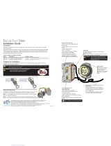
Lamp socket assembly
Reference Part Description Quantity
number number required
1 7060A3055 Housing, socket, casting, painted 1
2 7060A3057 Socket, light baffle casting, painted 1
3 7060A4007 Knob, X-Y, lamp set 1
4 7060A4008-02 Knob, Z, lamp set w/female insert 1
5 7060A4011 Bushing, cup 1
6 7060A3011 Hub, index, casting 1
7 7060A3012 Spring, lamp retainer 1
8 HW748 Spring, compression 1
9-11 M718 Complete TP22 450 degree-C CLCM assembly 1
9 W330-03 TP22 CLCM assembly, mica (1)
10 W330-04 TP22 CLCM 16-gauge, 1/4" semi-striped, Ni-gold contacts,
600V, 450˚C (2)
11 W330-02 TP22 CLCM assembly, ceramic (1)
12 HW534 Nut, hex, 1/4-20, black zinc 1
13 7060A3025 Screw, 1/4-20 knurled head 1
14 HW746 Retaining ring, flat, Southco 1
15 HW5123 Nut, hex, 9/16-18, black zinc 1
16 HW747 Washer, wave 1
17 7060A3056 Clamp, strain relief, painted 1
18 HW3103 Screw, 8-32 x 5/8 PhFHMS, black zinc 2
19 HW5122 Bolt, 1/4-20 x 1.75, full thread, black zinc 1
20 HW2125 Screw, self tap, 6-32 x 1/4, black zinc 1
21 7060B7003 48" W420 wire, 16 gauge, 200° C/300V, green
UL 1180/CSA AWM with lug J490T installed 1
22 W689 36" sleeve, fiberglass 1
23 HW749 Spring, ground 1
24 7060B7007 4" W420 wire, 16 gauge, 200° C/300V, green,
UL 1180/CSA AWM with two J490T lugs installed 1
25 7060A3085 Lamp retainer wire 1
26 HW8203 Tinnerman clip 1
7
16
18
14
8
12
22
6
4
10
21
17
19
11
23
1
2
3
5
9
13
20
15
26
25
24