Page is loading ...

ACADEMY
CITATION
BIOCHEM
GENOME
USER MANUAL

2
Phoenix User’s Manual
This manual contains details on installation and operation of your Phoenix Ultra-High Purity
water system. For optimum performance and safety please read and follow these instructions
carefully.
You have a quality, world class water treatment system that will provide ultrapure water for
many years of trouble free operation. Years of engineering and experience went into the
design and manufacture of this instrument which will dispense water exceeding Type I water
purity standards.
If you have any questions concerning the operation of the unit, or need service, refer
to "REQUESTING SERVICE".
In order that we may keep you informed regarding your unit, please take a moment to
complete the information below that will assist with support should it be needed.
Model Number: __________________________
Date: ________________________
Serial Number: ___________________________
Dealer: _______________________
Contact: _________________________________
Phone: _______________________
Conditioning Cartridge_____________________
Part Number ___________________
Polishing Cartridge _______________________
Part Number ___________________
Options Installed ________________________________________________________

Contents
System Information ........................................................................................................................ 4
General Arrangement ................................................................................................................. 4
Flow Diagram .............................................................................................................................. 5
Safety Information .......................................................................................................................... 5
Installation ...................................................................................................................................... 8
System Wall Mounting: Requires PHA-WB Wall Mount Bracket ............................................................. 9
Water Connections – All Models ............................................................................................................ 10
Remote Dispense (If Equipped) .............................................................................................................. 11
Remote Dispense Water Connections .................................................................................................... 11
Direct Feed Water Connection ............................................................................................................... 12
Electrical Connection .............................................................................................................................. 13
UV Lamp (If not already installed) (ACADEMY and GENOME) ............................................................... 13
Dual Conditioning Cartridge ................................................................................................................... 14
Polishing Cartridge .................................................................................................................................. 15
Initializing the System for the First Time ................................................................................................ 16
Normal Operation ......................................................................................................................... 18
Home Screen .......................................................................................................................................... 19
Batch Operations .................................................................................................................................... 20
Main Menu ............................................................................................................................................. 24
System Information ................................................................................................................................ 24
Configuration Menu ............................................................................................................................... 25
Alarm Log (Example Screen) ................................................................................................................... 25
Filter Detection and Leak Detection Errors ............................................................................................ 26
Maintenance ................................................................................................................................. 27
Adjusting Resistivity Alarm Set Points .................................................................................................... 28
Adjusting Recirculation Options ............................................................................................................. 29
Sanitization ............................................................................................................................................. 30
Troubleshooting ............................................................................................................................ 33
Specification Sheet ................................................................................................................... 36
Reordering Information ................................................................................................................ 38
Requesting Service ........................................................................................................................ 38
Entering Your Service Professional’s Contact Info ................................................................................. 38

System Information
The Phoenix Ultra High Purity Lab Water System delivers Type 1, 18.2 MΩ quality water on
demand. Water is purified in a staged process consisting of high-purity ion exchange resins to
remove dissolved minerals and internal recirculation to maintain purity. At discharge a final
0.2µm filter removes particulates and bacteria to attain Type 1 water specifications. Additional
optional technologies are incorporated depending on model. Multiple sensors continuously
monitor system and final water quality.
Model
Technology
Typical Applications
ACADEMY
Ion exchange
Particulate filtration
Basic Chemistry; Academic, IC, Buffers
CITATION
Ion exchange
185/254 nm UV
Particulate filtration
HPLC, GC-MS, Trace Organics
BIOCHEM
Ion exchange
Particulate filtration
Bacterial ultrafiltration
Life Science, Cell Culture, Microbiology
GENOME
Ion exchange
185/254 nm UV
Particulate filtration
Bacterial ultrafiltration
DNA Sequencing, PCR, Electrophoresis
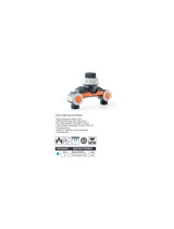
General Arrangement
Touch Screen Display
Power Input/Power Switch
Water Dispense Port
Feed Water Inlet
Conditioning
Cartridge
Polishing
Cartridge
Drain Port

5
Flow Diagram
Safety Information
DO NOT immerse in water or other liquid. Use a soft cloth and mild detergent when cleaning the
cabinet.
DO NOT remove the top cover with unit power applied.
DO NOT remove the ultraviolet lamp side cover with unit power applied.
DO NOT look directly at the ultraviolet lamp with unit power applied.
DO NOT operate with a damaged or frayed power cord. To disconnect the power cord, grip the plug
and pull it from the wall outlet, NEVER PULL ON CORD!
DO NOT use outdoors. This instrument is intended for commercial, industrial, institutional, and
professional use. Use of this product in a manner other than recommended may void the warranty.
DO NOT operate without proper connection to an adequate water supply and purged of air or damage
to the pump may occur.
DO NOT allow power cord to hang over the edge of a counter top or to touch hot surfaces. NOTE: If an
extension cord is used, verify that the rating of the extension cord is equal to or greater than the rating
of the instrument.
Refer servicing of a defective or damaged unit to the factory.
The use of filters or attachments not recommended by the manufacturer may adversely affect water
purity, cause damage, and void the warranty.
Avoid contacting the dispensing point with foreign materials or hands to prevent contamination.
WARNING Warnings indicate failing to observe instructions could result in injury or death.
CAUTION Cautions indicate failing to observe instructions could result in damage to
equipment.


7
See Mounting Bracket Template

Installation
Installation Requirements
• Power Requirements:
o “-1” Option - 120 VAC/ 60 Hz @ 1.0 amp
o “-2” Option – 220VAC / 50 Hz @ 0.5 amp
• GFCI protected outlet within:
o 6 feet for system
WARNING: Must be a grounded electrical connection.
• Feed Water Supply: Water source meeting minimum requirements as shown
below and located within 3 feet of the system.
Parameter
Requirement
Source/Type
Reverse osmosis (RO) or Service deionization (SDI) preferred. 0.2µm
particulate prefiltering is recommended for SDI and tap water feeds.
Conductivity
RO: < 20µS/cm
SDI: > 1 MΩ (Resistivity)
TOC (Using appropriate
conditioning as necessary)
RO: < 50 ppb
SDI: < 200 ppb
Temperature
20° F to 100°F (5° C to 38°C)
Pressure
20 psig minimum/90 psig maximum (1.38 to 6.21 bar)
Fouling Index
Silt Density Index: < 3
Dissolved Carbon Dioxide
< 30 ppm
Free Chlorine
< .05 ppm
• An upstream isolation shut off valve is highly recommended to facilitate future
servicing
• The Phoenix is supplied with an inlet connection for 3/8” OD tubing
• The Phoenix is supplied with an outlet drain port for 3/8” OD tubing
What you will need:
• #2 Phillips Head Screw Driver
• Teflon Tape
• Upstream Isolation Valve (Recommended)
• Basic Hand Tools (Adjustable wrench)
What you’ll find in the box:
• Phoenix System
• Certificates of Conformance
• Instructions
• Power cord
• Final Filter (Point of Use Filter)
• Drain Fitting
• 6’ Length of 3/8” Diameter Inlet Tubing & Drain Tubing

9
Optional (Depending on Model):
• UV Lamp (CITATION and GENOME)
• Dispensing Gun (PHA-DG)
• Remote dispense module and tubing (Models with –RMT-S Option)
• Wall mount bracket (PHA-WB)
System Wall Mounting: Requires PHA-WB Wall Mount Bracket
• Mount on a wall capable of supporting 50 lbs. Mounting directly to sheet rock is not
recommended.
• Mount bracket to wall. Holes in bracket are provided at 8”, 12” and 16” centers for
wall studs. If wall does not have studs mount proper backing, such as a plywood sheet
to the wall before mounting the bracket to it.
• Mount bracket with small slots in tabs pointing up.
• Align slots in system back plate with tabs on mounting bracket. Insert tabs into slots
and slowly lower system. Ensure all tabs are fully engaged and base of system is
parallel to floor.
• To lock PHOENIX system to the bracket, insert rubber bushing with screw and washer
(provided) into frame as shown. Tighten screw to lock wall bracket to frame.
Wall mount bracket
Insert bushing assembly
here to lock system to
bracket
Tabs pointing up

10
Water Connections – All Models
• 6 feet of tubing is provided for inlet
and drain connections.
• Feedwater inlet connection is made
through a 3/8” OD push to connect
fitting.
• Feedwater source should be located
within 3 feet of the Phoenix.
• The inlet is the bottom most fitting
on the right side of the Phoenix.
• Ensure tubing is pushed all the way
into fitting.
• An isolation shut off valve is
recommended for servicing purposes.
• Install supplied barbed drain fitting in
labeled drain opening on left side of
Phoenix.
• Insert 3/8” OD tubing (supplied) into
drain fitting and route the other end
to a suitable drain. If a leak occurs, it
will be contained by directing water
to the drain.
DRAIN

11
Remote Dispense (If Equipped)
Consideration should be given to location of the remote dispense module. Reference the diagram on
page 7. For example, the module can be mounted next to a sink so it would provide access to the sink
and adjacent countertop. The module can be mounted near the end of a countertop to provide access
to rolling carts for larger container fills as well as the countertop. Module should be mounted at a
height that provides access to the tallest container that will be used without blocking access to
cabinets.
For mounting the module, select a wall that is capable of supporting 20 lbs. The wall plate should be
mounted to a stud. Mounting directly to sheet rock is not recommended. If there is no stud at the
mounting location, mount proper backing such as a plywood sheet that is secured to studs before
mounting the plate to it.
Once a stud is located or support plate installed mark two holes on 5-13/16” centers and use a 3mm or
1/8” diameter drill to pre-drill holes to a depth of 2”. Use the two provided lag bolts to affix the plate.
While tightening the bolts ensure the mount is level.
10 feet of tubing is provided to connect the system and module. The system must located within this
distance bearing in mind that some slack should be allowed to provide access to the system for service.
Excess tubing can be coiled. 6 feet of drain tubing is also provided. Since the drain fitting is in the base
of the system, either access to a gravity fed floor drain or sump pump must be provided if the system is
installed below a sink. A 1-1/2” to 2” diameter hole must be provided where the umbilical containing
the water flow tubing and electrical connections will pass through a countertop.
Remote dispense electrical connection: Rotate connector to align tabs on umbilical plug with slots on
Phoenix socket and then insert plug. Repeat with the outer locking sleeve. When slots and tabs are
aligned, push and turn to lock connector in place.
Remote Dispense Water Connections
• Install upstream isolation valve in
feedwater line (recommended).
• Connect 3/8” OD white recirculation
return tubing from umbilical into
Return fitting.
• Connect 3/8” OD clear tubing from
umbilical into Outlet fitting.
• Make sure tubing is fully seated into
fittings.

12
Direct Feed Water Connection
For systems plumbed with a direct feed option, an additional outlet port is provided on the side of
the system above the feed water inlet. To connect the system to the remote demand, a
male/female valved fitting has been supplied. When the two halves are detached water will not
flow from the direct feed outlet port.
The female side has a short 3/8” tube extension. This tube is inserted into the outlet port.
The male side (with O Ring) is provided already attached to a length of 3/8” OD plastic tubing.
The direct feed connection must be bled during initial rinse after bleeding the
cartridges. Place the outlet end of the tubing in a drain or container. Insert and
connect the male/female fittings as shown. The female fitting has a metal locking
collar to prevent separation. Pull on the connection to verify it is engaged and does
not leak.
Observe the water stream. When air bubbles no longer appear disconnect the fittings.
It is the user’s responsibility to connect the outlet tubing to their demand instrumentation
providing appropriate sizing adapters as necessary. After doing so, reconnect the male and female
connectors.
Caution: Using the standard dispense port while the direct feed option is in use will reduce the
system flow rate.
`
Direct feed outlet port
System feedwater inlet
To direct feed demand
(tubing provided)
Male connector
(provided)
Valved female
connector
(provided)
Insert tubing end
into outlet port

Electrical Connection
• Power switch is located on left side
of system
• Ensure power switch is in OFF
position
• Insert power cord into electrical
connection module
• Insert other end of cord into GFCI
power source
WARNING: Must be a grounded
electrical connection
UV Lamp (If not already installed) (ACADEMY and GENOME)
To install lamp:
• Remove left side panel access screw
• Remove left side panel
CAUTION: Wear gloves when
handling UV lamp to avoid
contaminating lamp
• Slide boot away from socket to
provide access for plug connection
• Connect lamp to socket before
placing lamp in UV chamber
• Insert lamp slowly into chamber
• Secure boot fully over socket
• Replace side panel
UV
lamp
boot
Electrical
connection
module

14
Dual Conditioning Cartridge
• Remove cartridge from packaging
`
Caution: Remove plastic plugs
from inlet and outlet before
proceeding
• Open blue door and lift lever on left
side of dual conditioning cartridge
mechanism
• Insert conditioning cartridge. Align
base of cartridge with contour in
base of system
• Slowly lower lever making sure
fittings align with the openings in
the cartridge.
Caution: DO NOT APPLY
EXCESSIVE FORCE when
lowering lever or damage
may occur. Realign cartridge
and fittings if significant
resistance is felt.
• Ensure lever is in its fully down and
locked position

15
Polishing Cartridge
• Remove cartridge from packaging
Caution: Remove plastic plugs
from inlet and outlet before
proceeding
• Open right side white door (It may be
convenient to open blue door as well)
• Raise and hold lever on right side of
mechanism
• Insert cartridge with openings facing
system
• Flanges on sides of cartridge cap rest
on alignment guide
• Push cartridge toward system until it
stops
• Slowly lower lever to secure cartridge.
Cartridge will be drawn into final
position by mechanism
• Ensure lever is in its fully down and
locked position
Alignment
guide

16
Initializing the System for the First Time
Note: This is for the first time set-up only. In the on-screen directions you will be skipping steps
that would normally be required during consumable replacement.
Note: Some steps are applicable only to individual PHOENIX models. If your PHOENIX does not
have a UV lamp and/or Ultrafilter, these components will be greyed out on the Home Screen
Display.
• Ensure feed water supply is on and connected to system.
• Turn on power switch. Splash screen will display.
• Press START. Home Screen will display.
• After a 10 second delay, the pump will start and the system will begin the initial rinse cycle.
TO ACTIVATE THE ULTRAFILTER FOR BIOCHEM AND GENOME Models:
• Press and hold the ULTRA FILTER icon and press NEXT to initialize the Ultra Filter.
• Follow the instructions displayed.
o Skip on-screen instruction for Steps 5 and 6 as the ultrafilter is already installed.
o During Step 9, the purging process may take several minutes.
o Complete the procedure by pressing RESTART to return to the Home Screen.
TO ACTIVATE THE UV LAMP FOR CITATION and GENOME Models:
• From the Home Screen, press and hold the UV LAMP icon. Press NEXT to continue.
o Follow instructions displayed. It will not be necessary to replace lamp.
o Complete the procedure by pressing RESTART to return to the Home Screen.
TO ACTIVATE THE FILTER PACKS FOR ALL MODELS:
• From the Home Screen, press and hold the CONDITIONING icon. Press NEXT to continue.
o Follow instructions displayed. As this is the first time initialization process a new
pack should have been installed. It will not be necessary to replace the pack as
specified in the instructions.
o Complete the procedure by pressing RESTART to return to the Home Screen.
• From the Home Screen, press and hold the POLISHING icon. Press NEXT to continue.
o Follow instructions displayed. As this is the first time initialization process a new
filter should have been installed. It will not be necessary to replace the filter as
specified in the instructions.
o Complete the procedure by pressing RESTART to return to the Home Screen.

17
• Remove the final filter from its packaging
• Wrap 3 to 5 turns of Teflon tape on the filter threads and install into the outlet.
o Place container under final filter.
o Press the dispense button.
o Purge air by slowly turning the vent port CCW until a steady stream of water is seen.
o Press the dispense button and retighten vent port once all air is purged.
Vent
port
Final filter (Point of Use Filter)

18
Normal Operation
Normal sequence of operation:
Resistivity display will flash during the 2 hour initial rinse. After completion, the system enters
Polishing mode for 2 minutes in which the inlet solenoid is open and the pump is on. The UV lamp
is also on if equipped. Polishing mode recirculates water internally to maintain water purity. The
system continuously monitors water quality, system performance and consumable health. System
parameters for recirculation can be adjusted. See “Adjusting Recirculation Options”.
NOTE: Initial rinse can be bypassed to enter Polishing mode by holding the Initial Rinse button at
the bottom of the display for 3 seconds. This is useful if the system is restarted with previously
rinsed consumable packs.
Following Polishing, the system will automatically enter Standby mode and will display WAKE. This
is a 10 minute dwell to conserve system power and consumables. If equipped, the UV lamp is also
turned off. Standby mode can be bypassed by pressing the WAKE button to refresh water before
dispensing. If not bypassed the system will automatically enter Polishing mode at the end of the
dwell and will continue to alternate between Polishing and Standby.
Dispensing water will bring the system into Polishing mode if it is in Standby.
Final water quality after the Polishing filter (resistivity) is shown on the Home Screen. The value is
shown against a white background. Resistivity at the output of the conditioning pack can be
displayed by pressing the resistivity value. The display will change to a colored background
indicating it is the value after the conditioning pack. The display will return to final output water
quality after 5 seconds.
Direct feed operation (If equipped):
The system is equipped with a pressure switch that senses downstream water demand. When this
occurs the system enters direct feed mode and Direct Feed will display. The inlet solenoid and
pump will come on and remain running. The system will monitor the direct feed pressure and will
enter Polishing mode when demand stops for more than one minute.
Caution: The direct feed outlet connection must be bled during initial rinse after
bleeding the Dual Conditioning Cartridge and Polishing Cartridge. See the Direct
Feed Connection Section.
Water can be dispensed from the main outlet port during direct feed operation.

19
Home Screen
RECIRCULATION MODE
• INITIAL RINSE
• POLISH
• STANDBY
• DIRECT FEED
DISPENSE
Press to toggle
dispensing of water
RESISTIVITY
Displays Polishing
Cartridge resistivity.
Press to display
Conditioning Cartridge
resistivity. Press and
hold to display Alarm
set points
CONSUMABLE REPLACEMENT
ICONS
Press and hold any
component to display
replacement information
and instructions
CONSUMABLE HEALTH
Displays current status
of consumables:
•
GREEN – Full life
•
YELLOW – Partial
life
•
RED – Needs
replacement
See MAINTENANCE
Section for more
details
BATCH
Press to display the
BATCH SELECT menu
MENU
Press to display Main Menu
ALARM STATUS
GREEN CHECK:
No Alarms
RED “X”:
Alarm present

20
Batch Operations
To Dispense, Modify, Teach, Label or Clear a batch press the “Batch” button (the button showing 3 water
droplets). The Batch Select screen opens.
Main Screen
Batch Select Screen
To use a batch (1 through 6), to dispense a designated volume of water, press and release on its number
icon on the Batch Select screen.
To modify / teach / clear / label a batch, press and hold (about 3 seconds) the desired batch number icon
until a long beep is heard. The Batch Edit screen opens.
Batch
Button
Batch
Number
Icon
Displays Polishing
Cartridge resistivity
/