Page is loading ...

Voice Evacuation System
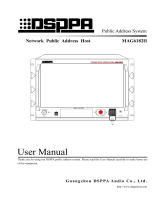
2 Zones Integrated Voice Evacuation System Host
PAVA2240
EME RGENCY
AC POW ER
STAT US
SYS STATE
DC C HARGE
EMG MIC
ZONE 1 ZONE 2
EME RGENC Y MIC
MAST ER
TREBL E
BASS
DC POWE R
INDIC ATION
TEST
EVAC MSG ALERT MSG
EVAC /ALERT
PAGI NG
STATE
BGM
EVA C VOI CE CO NTROL
ACK/R ESET
PAVA2240
Comp act Voice Evacuati on System
User’s Manual
Welcome to DSPPA Voice Evacuation System! Please read the Instructions carefully before operating this device.
Guangzhou DSPPA Audio CO., Ltd
http://www.dsppatech.com

This page is left for users notes

About the Instructions
The Instructions is used at the date when the PAVA2240 2 Zones Integrated Voice Evacuation System
Host device is developed. It contains system introduction, operation attentions, system connection
instructions, product instructions and other contents of the PAVA2240 2 Zones Integrated Voice
Evacuation System Host device. The user shall read the Instructions carefully and operate the device
following the indications in the Instructions before the installation and operation of the device.
Any symbol marked on the rear panel of this machine must be noted. The operations must be
performed according to the instructions of these symbols.
Please keep the Instructions for future reference!
PAVA—V0.7
Facture 2019-12-13

WARNING
Be sure to observe the following cautions to prevent the damage to the users and others, and the
damage to the equipment or property!
This symbol means a “prohibition”. This symbol means a “must”.
Check the damage condition of power cord.
Do not pulling the power cord to unplug the plug,
unplug the plug directly; otherwise it may cause
electric shock, short circuit or fire.
Do not block the air vent during the operation.
All air vents must be unblocked to avoid the
overheating.
Do not expose the device to dust, vibration,
extreme cold and hot environment.
Do not place heavy objects on the device. Do not
impose an excessive force when operating the
switch, buttons or connecting the external audio
equipment.
Avoid any foreign matter (paper, metal, etc.)
from entering the device through gap or opening.
In such a case, please power off this device
immediately.
Do not attempt to detach the internal parts of this
device or remold it by any way.
Please unplug the power plug immediately to
avoid the electric shock, fire or other accident and
professionals shall be invited for maintenance of
the device in case of any sudden sound
interruption, any abnormal smell or smoke during
the running of the machine.
Smell of Scorching
Be sure to unplug the AC power cord or turn off
the wall outlet to achieve zero energy consumption
when this device will not be operated for a long time.

* * Voice Evacuation System
i
CONTENTS
1. Product Description.................................................................................................................................................. 1
1.1 Brief introduction....................................................................................................................................................1
1.2 Performance............................................................................................................................................................ 1
2. Appearance Description............................................................................................................................................2
2.1 Description of Front Panel......................................................................................................................................2
2.2 Description of Output Panel................................................................................................................................... 5
3. Connection Instructions............................................................................................................................................ 7
3.1 System connection diagram....................................................................................................................................7
3.2 Interface linkage diagram....................................................................................................................................... 8
4. Methods for examining common system failures.................................................................................................... 9
5. Installation instructions...........................................................................................................................................10
5.1 Installation size..................................................................................................................................................... 10
5.2 Steps to install....................................................................................................................................................... 10
Packing List.................................................................................................................................................................12
Specifications..............................................................................................................................................................13

* * Voice Evacuation System
1
1. Product Description
1.1 Brief introduction
PAVA2240 is an integrated voice evacuation system host. With built-in 240W digital amplifier, not only can it
send out warning and alarm, but also support handhold microphone to make voice evacuation. It can manage
emergency alarming, fire alarm announcement and background music playing for 2 zones. It is an ideal
application for small shopping malls, office building and sports venues.
1.2 Performance
Digital tube display screen to display time, power amplifier status, and
Fireman MIC
status;
One-key alarm and two kinds of editable alarm voices; EMC microphone for on-site voice evacuation;
LED light to indicate system connection status and fault status;
Support speaker line detection (light load, over load and short circuit);
LED display to indicate the type of audio source of the current signal;
1 aux input interface, 1 Fireman MIC input, support offline detection; each paging record is automatically
saved to SD card;
Zone switch keys and LED display to indicate zone working status;
Support AC power supply and 24V battery power supply; support automatically and seamlessly identify and
convert. AC power supply is with the priority;
Built-in two 240W digital power amplifier modules, which can have master and standby amplifier switch
automatically;
Equipped with 24V battery charger, which can be charged automatically when the system is powered by AC;
System error information is backed up by logging in SD card;
A/B line speaker output for two zones; independent power switch and volume control for each zone; with
master volume control, treble and bass adjustment; each channel can output 240W, and the total power of 2
zones need to be within 240W;
2 channel link relay output interface (can control the short circuit of two wires to control other equipment); 2
24V output interfaces give peripheral equipment 24V (not greater than 0.5A) input signal;
2 input dry contacts, which can be integrated with the third-party system (such as the fire alarm system)
through the input of dry nodes;
Network cable interface for connecting to PAVA2200 Fireman MIC;
With system LED test function button.

* * Voice Evacuation System
2
2. Appearance Description
2.1 Description of Front Panel
EME RG ENCY
AC P OWER
STA TUS
SYS ST ATE
DC CH AR GE
EMG MIC
ZONE1 ZONE2
EME RG ENCY MIC
MAS TER
TRE BLE
BASS
D C PO WER
INDICATION
TEST
EVA C MSG ALERT M SG
EVA C/ALERT
PAGING
STAT E
BGM
EVA C V OI CE CO NTROL
ACK /RESET
1
2
3
4
5
7
6
8
9
10
11
12
19
20
21
23
24
25
13
14
15
16
17
18
22
1. Handheld microphone connection interface
For connecting and fixing the handheld microphone;
2. Confirmation button◎
Long press this button to enter time modification;
3. Right button
Press to move right;
4. Up button: to add 1
When the system is working under the state of voice evacuation instead of time modification, press this button
to increase the volume of voice alarming. After setting, the system will save the volume automatically;
5. Down button: to minus 1
When the system is working under the state of voice evacuation instead of time modification, press this button
to decrease the volume of voice alarming. After setting, the system will save the volume automatically;
6. Digital screen: to display time and amplifier’s status
To set system time: long press ◎ to set system time. First set the year, as digital is flashing, press UP and
DOWN button to adjust the number of year. Press the right button to move the flashing digital. After the year
setting, press the right button to move to month setting. After setting hours and munities, click the
confirmation ◎ button to end time modification. After setting, the time is displayed at regular intervals.
When the main amplifier fails, the screen will display E1; when the standby amplifier fails, the screen will
display E2; when the connection number of Fireman MIC changes, bN will be displayed (N means the

* * Voice Evacuation System
3
Fireman MIC with address N is disconnected).
7. System working mode indicator
Flashing Red -- the current system works in emergency mode;
Off -- the current system works in normal mode;
Enter emergency mode:
In normal mode, press this button, the red indicator light flashes to indicate the emergency mode is
entered.
Exit emergency mode:
In emergency mode, press this button to exit and stop playing EVAC voice messages and zone output.
Note: both the entry and exit time or mode can be checked in the "LOG" of PAVA2240.
8. Main power indicator:
Green -- indicates the AC power supply of the device is normal;
Orange -- indicates that the device is not connected to AC power supply;
9. DC 24V battery indicator
Green -- indicates power supply of DC24V battery is normal;
Orange -- indicates that DC24V battery is not equipped with the device;
10. Charger status indicator:
Green -- indicates the current charger is charging;
Yellow - indicates that the charger is not equipped or damaged;
Off - indicates that the charger is equipped but not charging;
11. System status indicator:
Green -- all modules of the system work normally;
Flashing orange -- the system is abnormal (press ACK/RESET if you are sure the system is working
normally);
12. Handheld microphone status indicator:
Yellow – indicates the handheld microphone is lost or malfunctioning;
Green -- the microphone is working;
Off -- the handheld microphone is normal but not working;
13-14. EVAC voice message status indicator:
Green -- "EVAC MSG/ALERT MSG" voice message is broadcasting;
Yellow -- "EVAC MSG/ALERT MSG" voice message is lost or SD card is lost;
Off -- "EVAC MSG/ALERT MSG" is normal;
Note:
1. "EVAC voice message" refers to both EVAC voice and ALERT voice;
2. If the EVAC voice message needs to be played manually, the user needs to enter the emergency mode
first and then press the voice message button;
15. Speaker status indicator
Yellow – indicates the impedance of zone A or B (speaker A or B) changes; there might occur open

* * Voice Evacuation System
4
circuit or short circuit;
Off -- the impedance variation of the current speaker circuit is within the impedance range of the
speaker when it is under modeling;
16. Background music indicator
Green -- background music is running;
Off - background music is off;
Note: the system plays background music in the default if there isn’t any other input signal;
17. Fireman MIC indicator
Green – on paging;
Off – not paging;
Note: Zones can be ON and OFF manually while paging;
18. Voice evacuation message (from SD card) indicator
Green – voice evacuation message is on;
Off -- no voice evacuation message;
Note: Zones can be ON and OFF manually;
19. Zone 1 indicator
Green -- zone 1 is on;
Off -- zone 1 is off;
20. Zone 2 indicator
Green -- zone 2 is on;
Off -- zone 2 is off;
21. LED test indicator
Press this key to enter the LED test mode;
22. Confirm/reset/model key
If the system module is diagnosed as abnormal, the "SYS STATE" fault indicator will flash intermittently.
After pressing this button, the "SYS STATE" long light will no longer flash to indicate its fault status, and
the buzzer will stop. When there is new module detected to be abnormal, the "SYS STATE" LED light
flashes and the buzzer is on again;
Long press for impedance modeling and the number of Fireman MICs modeling. Please conduct a modeling
every time when the speakers are connected and the Fireman MIC is connected.
23-24. Bass and treble control knob
25. Master volume control knob

* * Voice Evacuation System
5
2.2 Description of Output Panel
100V 0V
Line A
ZONE1
Line B
100V 0V
GNDIN
1 2
Contact Mode
K
1 2
Contact Mode
K
24V
Zone 1
24V
Zone 2
Paging nterface
Primary
Secondary
24V
IN
100V 0V
Line A
ZONE1
Line B
100V 0V
RISK OF ELECTRIC SHOCK
DO NOT OPEN
CAUTION
广州市迪士普音响科技有限公司
Guangzhou DSPPA Audio Co.,Ltd.
~220V/50Hz
8
100V 0V
Line A
ZONE1
Line B
100V 0V
GNDIN
1 2
Contact Mode
K
1 2
Contact Mode
K
24V
Zone 1
24V
Zone 2
Paging nterface
Primary Secondary
24V
IN
100V 0V
Line A
ZONE1
Line B
100V 0V
2 3 4 5 61 7
100V 0V
Line A
ZONE1
Line B
100V 0V
1 2
Contact Mode
K
1 2
Contact Mode
K
24V
Zone 1
24V
Zone 2
Paging nterface
Primary Secondary
24V
IN
100V 0V
Line A
ZONE1
Line B
100V 0V
GNDIN
100V 0V
Line A
ZONE1
Line B
100V 0V
GNDIN
1 2
Contact Mode
K
1 2
Contact Mode
K
24V
Zone 1
24V
Zone 2
Paging nterface
Primary
Secondary
24V
IN
100V 0V
Line A
ZONE1
Line B
100V 0V
RISK OF ELECTRIC SHOCK
DO NOT OPEN
CAUTION
Guangzhou DSPPA Audio Co.,Ltd.
~220V-230V/50Hz/2A
8
100V 0V
Line A
ZONE1
Line B
100V 0V
GNDIN
1 2
Contact Mode
K
1 2
Contact Mode
K
24V
Zone 1
24V
Zone 2
Paging nterface
Primary
Secondary
24V
IN
100V 0V
Line A
ZONE1
Line B
100V 0V
2 3 4 5 61 7
100V 0V
Line A
ZONE1
Line B
100V 0V
1 2
Contact Mode
K
1 2
Contact Mode
K
24V
Zone 1
24V
Zone 2
Paging nterface
Primary
Secondary
24V
IN
100V 0V
Line A
ZONE1
Line B
100V 0V
GNDIN
1. A&B line output for 2 zones
Output voltage is 0~100V;
Note: please conduct modeling of speakers at least once after connection, and long press ACK/RESET button;
zone without connecting speakers can be left empty.
2. BGM line input
3. Fireman MIC interface
For connecting Fireman MIC PAVA2200;
Support looping connection and branch connection (as shown in the below picture), and the software can
recognize automatically;
Looping connection Branch connection
4. Input dry contacts of 2 zones
Under normal conditions, keep the interface always open. When dry contact 1 detects short circuit, zone
1 and 2 play ALERT voice. When dry contact 2 detects short circuit, zone 1 and 2 play EVAC voice.
(The dry contact can also be triggered by inputting a 5V-24V high level, simply move the internal short
100V 0V
Line A
ZONE1
Line B
100V 0V 100V 0V
Line A
ZONE2
Line B
100V 0V
GND IN
1 2
Contact Mode
K
1 2
Contact Mode
K
24V
Zone 1
24V
Zone 2
Paging nterface
Primary
Secondary
2 3 4 5 61
100V 0V
Line A
ZONE1
Line B
100V 0V 100V 0V
Line A
ZONE2
Line B
100V 0V
GND IN
1 2
Contact Mode
K
1 2
Contact Mode
K
24V
Zone 1
24V
Zone 2
Paging nterface
Primary
Secondary
2 3 4 5 61
EMERGENCY
AC POWER
STATUS
SYS STATE
DC CHARGE
EMG MIC
ZONE1 ZONE2
EMERGENCY MIC
MASTER
TREBLE
BASS
DC POWER
INDICATION
TEST
EVAC MSG ALERT MSG
EVAC/ALERT
PAGING
STATE
BGM
EVAC VOICE CONTROL
ACK/RESET
PAVA 2240
Compact Voice Evac uatio n Syst em
EMERGENCY
AC POWER
STATUS
SYS STATE
DC CHARGE
EMG MIC
ZONE1 ZONE2
EMERGENCY MIC
MASTER
TREBLE
BASS
DC POWER
INDICATION
TEST
EVAC MSG ALERT MSG
EVAC/ALERT
PAGING
STATE
BGM
EVAC VOICE CONTROL
ACK/RESET
PAVA 2240
Compact Voice Evac uatio n Syst em
EMERGENCY
AC POWER
STATUS
SYS STATE
DC CHARGE
EMG MIC
ZONE1 ZONE2
EMERGENCY MIC
MASTER
TREBLE
BASS
DC POWER
INDICATION
TEST
EVAC MSG ALERT MSG
EVAC/ALERT
PAGING
STATE
BGM
EVAC VOICE CONTROL
ACK/RESET
PAVA 2240
Compact Voice Evac uatio n Syst em
EMERGENCY
AC POWER
STATUS
SYS STATE
DC CHARGE
EMG MIC
ZONE1 ZONE2
EMERGENCY MIC
MASTER
TREBLE
BASS
DC POWER
INDICATION
TEST
EVAC MSG ALERT MSG
EVAC/ALERT
PAGING
STATE
BGM
EVAC VOICE CONTROL
ACK/RESET
PAVA 2240
Compact Voice Evac uatio n Syst em

* * Voice Evacuation System
6
circuit cap to the right).
5. Output dry contacts of 2-channel relay
Under normal conditions, the output dry contact 1 is an open circuit. When an EVAC or ALARM plays,
the output dry contact open circuit becomes short-circuited.
Under normal conditions, the output dry contact 2 is a short circuit. When the system fails, the dry
contact will be changed from short circuit to open circuit.
6. 24V output
Under normal conditions, there is no output. When the system is in alarm state, the two 24V output ports
change from no output to 24V output.
7. DC24V power input interface
8. AC 220V-230V power cable

* * Voice Evacuation System
7
3. Connection Instructions
3.1 System connection diagram
s
Other devices
PAVA2200 Fireman MIC
PAVA2200 Fireman MIC
PAVA2240 2 Zones Integrated Voice Evacuation System Host
speakers
AUX input
Alarm enter
Network cable
EMERG ENCY
AC P OWER
STATUS
SYS S TATE
DC CH ARGE
EMG M IC
ZONE1 ZONE2
EMERG ENCY MIC
MASTE R
TREBLE
BASS
DC POWER
INDICA TION
TEST
EVAC MSG ALE RT MSG
EVAC/ ALERT
PAGING
STATE
BGM
EVAC VOICE CO NTROL
ACK/RE SET
PAVA2240
Comp act Vo ice Evacuat ion System
Fireman Microphone
PAVA2200
POWER
COMMUNI CATION
EMG MI CROPHONE
STATUS
EMERGEN CY
FAULT AC K INDICATI ON TEST
EVAC MSG AL ERT MSG
EVAC V OICE CONTROL
ZONE 01
ZONE SE LECT
NULL
ZONE 02
NULL
POWER
COMMUNI CATION
EMG MI CROPHONE
STATUS
EMERGEN CY
FAULT ACK IND ICATION TEST
EVAC MSG ALE RT MSG
EVAC V OICE CONTROL
ZONE 01
ZONE SE LECT
NULL
ZONE 02
NULL
6
7
8
9
10
11
12
13
14
5
1
2
3
4
SYS STATE
SYS STATE

* * Voice Evacuation System
8
3.2 Interface linkage diagram
100V 0V
Line A
ZONE1
Line B
100V 0V
GNDIN
1 2
Contact Mode
K
1 2
Contact Mode
K
24V
Zone 1
24V
Zone 2
Paging nterface
Primary
Secondary
24V
IN
100V 0V
Line A
ZONE1
Line B
100V 0V
RISK OF ELECTRIC SHOCK
DO NOT OPEN
CAUTION
广州市迪士普音响科技有限公司
Guangzhou DSPPA Audio Co.,Ltd.
~220V/50Hz
8
100V 0V
Line A
ZONE1
Line B
100V 0V
GNDIN
1 2
Contact Mode
K
1 2
Contact Mode
K
24V
Zone 1
24V
Zone 2
Paging nterface
Primary Secondary
24V
IN
100V 0V
Line A
ZONE1
Line B
100V 0V
2 3 4 5 61 7
100V 0V
Line A
ZONE1
Line B
100V 0V
1 2
Contact Mode
K
1 2
Contact Mode
K
24V
Zone 1
24V
Zone 2
Paging nterface
Primary Secondary
24V
IN
100V 0V
Line A
ZONE1
Line B
100V 0V
GNDIN
Note: PAVA2240 can support power supply for maximum 2 pcs PAVA2200 Fireman MIC. Looping and branch
connection are supported.
speakers
speakers
PAVA2240 2 Zones Integrated Voice Evacuation System Host
1:BIN-ID1
OUT IN
2:BIN-ID2
3:BIN-ID3
4:BIN-ID4
5:BIN-ID5
6:MOM -PAG E&PPT-PAGE
7:INDI -ZON E&GROUP-ZONE
8:INDI CATOR TEST
Link ID
1 2 3 4 5 7 86
ON DIP
Alarm center
PAVA2200 Fireman MIC
Other devices
24V input
1:BIN-ID1
OUT IN
2:BIN-ID2
3:BIN-ID3
4:BIN-ID4
5:BIN-ID5
6:MOM -PAG E&PPT-PAGE
7:INDI -ZON E&GROUP-ZONE
8:INDI CATOR TEST
Link ID
1 2 3 4 5 7 86
ON DIP
PAVA2200 Fireman MIC
This cable can be removed in branch
connection way
Network cable

* * Voice Evacuation System
9
4. Methods for examining common system failures
1. When the digital screen displays b1, please:
check if the network cable for connecting PAVA2200 is loose.
2. When the DC POWER indicator is yellow, please:
check if there input AC power
3. For the device and extended device, when the SYS STATE indicator is yellow, it indicates that there is
a fault in the system detection. Please:
check if the digital tube displays error messages
check if the LED light with detection function is abnormal
4. When the EMG MIC indicator is yellow, please:
check if the handheld microphone is normal
5. When the STATE indicator for each zone is yellow, please:
check if the speaker cable of the corresponding zone is broken or damaged.

* * Voice Evacuation System
10
5. Installation instructions
5.1 Installation size
后视图
左视图
右视图
仰视图
俯视图
180
350
240
75
400
Back view
Left view
Right view
Top view
Bottom view
180
350
124.5
240
75
400
428
500
428
500
5.2 Steps to install
1) Open the package of this device and check whether the device and accessories are complete by referring to
the "packing list" at the end of the manual;
2) First remove the top fender of the casing, then connect the cables through the top of the casing (such as
network cable, audio cable, etc.), and then fix the top fender of the casing;
3) Then fix one end of the two triangle accessories on the bottom of the casing with screws;
4) According to the hole size on the back panel of the casing as to the above picture, nail 2 pcs M6 self-tapping
screws on wall or other solid surfaces;
5) After confirmation, align the two holes with screws and hang the device on wall or other solid surfaces;
6) Finally, fix the other end of the two triangle accessories on wall or other solid surfaces with screws.
Note: please ensure that this device and other devices connected to this system are not in power during the
installation process!
Installation size
Cable outlet
Cover 1
Cover 2
The holes on the back of
the case should be aligned
with the wall screws
Triangle
accessory
back baffle

* * Voice Evacuation System
11
Safety Precautions
1.Precautions for Safe Operation
Do not plug the power cord into the power grid before the system line is not connected.
Be sure that the input voltage of the device is exactly the same as the voltage required for this device.
Otherwise it may burn the device.
Do not open the case without authorization in order to avoid the risk of electric shock because there is a
dangerous voltage in the device.
Please unplug the power cord from the socket for the sake of safety when the device will not be used because
the device is not completely disconnected from the power grid when the device is powered off.
Do not put the device in a super-cooling or superheating place.
Be sure there is a well-ventilated operating environment to avoid the heat and excessive temperature from
damaging the device during the operation.
Please unplug the power plug in rainy or wet days or without operation for a long time.
Be sure to unplug the power plug to ensure the complete disconnection from the power grid before detaching
or re-install any parts of the device, disconnecting or re-connecting any electrical plugs of the device or
performing any connection.
Do not open the case to repair the device without authorization in case of any fault in order to avoid the
accident or aggravate the damage of the device.
Do not put any corrosive chemicals on or near the device.
2.Precautions for After-Sale Services
The Company will provide the free warranty services of three years (including replacement of parts free of
charge) for any quality problem occurred since the date of purchase if the user installed and operated the
device as required and it is within the range of normal operation.
For any warranty, the user must provide the warranty card, user’s self-deposit stub invoice and sales invoice
as the voucher.
Any of the following circumstances is not included in the range of free warranty:
1. Damage of product resulted from the incorrect installation, operation or handling;
2. Damage of product resulted from any abnormal condition, for example, excessive power voltage or
environment humidity, etc.
3. Damage of product resulted from any natural disasters or other accidents;
4. The serial number of the products on the shell is converted, altered or removed;
5. The product was once repaired or modified by others rather than the authorized personnel of the Company;
Please keep the Instructions and Warranty Card properly;
For any question or attentions not covered in the Instructions, please feel free to contact our dealer or visit
our website at: http://www.DSPPA.com, http://www.dsppatech.com.

* * Voice Evacuation System
12
In case of any fault during the warranty period, please feel free to contact our service personnel or dealers for
maintenance treatment. The Company will not bear any responsibility of free warranty for any damage
resulted from the unauthorized demolition of the users themselves or the repair of others rather than the
technical staff of the company.
Packing List
No.
List
Quantity
1
PAVA 2240 the device
1
2
User’s manual
1
3
Certificate
1
4
Warranty
1
5
CB100 microphone
1
6
4P green plug 3.81MM
3
7
4P bent pin male plug 5.08MM
2
8
2P green plug 5.08MM
1
9
TF card 16G
1
10
Semicircle head cross belt interconnect wire M4
4
11
200MM/red wire
1
12
PAVA2240 casing accessory 2
2
13
plastic post expansion pipe M6
8
14
Semicircle head cross band interface self – attack M6
8

* * Voice Evacuation System
13
Specifications
Items
Index
Rated power output
240W (Note: please connect high impedance speaker within
this load)
Rated voltage output
100V
Sensitivity
Microphone
5mv(±1mv)
Line input
1VRMS(±100mv)
SNR
Microphone
≥70dB
Line input
≥80dB
Frequency response
Microphone
100Hz~10KHz(±3dB)
Line input
80Hz~15KHz(±3dB)
The ratio of source electromotive force
≥12dB
Total harmonic distortion
≤0.5%
Tone adjustment range
±11±2 dB
Rated power consumption
350W
AC-DC power supply switching time
No intermittent
Main and standby amplifier switching time
No intermittent
Battery life of 12AH (two batteries in series
form 24V)
2H (voice evacuation works normally)
Battery specs
Size
≤150×100×100mm ( 2 pcs)
Voltage
12V; (use two in series to make 24V)
Power supply
AC220V-230V/50Hz
Packing size
570×470×271mm
Machine dimensions
500×400×180mm
Gross weight
17KG
Net weight
15KG (without batteries)
Technical specifications are subject to change without prior notice.

* * Voice Evacuation System
14
Guangzhou DSPPA Audio Co., Ltd
Cautions
Please unplug the power cord plug from the socket for the sake of safety when the device will not be used
because the device is not completely disconnected from the power grid when the power switch of the device
is in OFF state.
The device cannot be subject to water droplets or splashes and any items like vases filled with water cannot
be placed on this device.
Do not open the cover of the machine to prevent the electric shock. If necessary, it shall be repaired by the
professional with the professional certificate.
The terminal marked with a symbol in the device indicates that it is dangerous and charged. The
connecting operation of these terminals shall be performed by the trained staff.
The device is connected with the power grid via the power cord plug, so, the connection between the device
and the power grid can be cut off by unplugging the power cord plug in case of any fault or danger.
Therefore, the power outlet is required to be mounted at a place where the plug of the power cords can be
easily unplugged or plugged.

* * Voice Evacuation System
注意:此页不打印
广州市迪士普音响科技有限公司
型号名称
PAVA2240 2分区简易紧急语音系统主机
英文说明书
内容修改
修改PAVA2240和PAVA2200面板丝印EVAC
VIOCE CONYROL为EVAC VOICE CONTROL
版本
V0.6
审核:
编制
王小胜
批准:
日期:
2019-11-21
/