Eaton Series NRX Installation Instructions Manual

Category
Networking
Type
Installation Instructions Manual
Effective December 2010
Supersedes March 2010
IL01301034EH02
Instructional Leaflet IL01301034E
Installation instructions for Series
NRX
Modbus communications
adapter
module (MCAM)
WARNING
(1) ONLY QUALIFIED ELECTRICAL PERSONNEL SHOULD BE
PERMITTED TO WORK ON THE EQUIPMENT.
(2) ALWAYS DE-ENERGIZE PRIMARY AND SECONDARY CIRCUITS
IF A CIRCUIT BREAKER CANNOT BE REMOVED TO A SAFE WORK
LOCATION.
(3) DRAWOUT CIRCUIT BREAKERS SHOULD BE LEVERED (RACKED)
OUT TO THE DISCONNECT POSITION.
(4) ALL CIRCUIT BREAKERS SHOULD BE SWITCHED TO THE OFF
POSITION AND MECHANISM SPRINGS DISCHARGED. FAILURE
TO
FOLLOW THESE STEPS FOR ALL PROCEDURES
DESCRIBED IN THIS
INSTRUCTION LEAFLET COULD RESULT IN DEATH, BODILY INJURY,
OR PROPERTY DAMAGE.
WARNING
THE INSTRUCTIONS CONTAINED IN THIS IL AND ON PRODUCT
LABELS HAVE TO BE FOLLOWED. OBSERVE THE FIVE SAFETY RULES:
DISCONNECTING
ENSURE THAT DEVICES CANNOT BE
ACCIDENTALLY RESTARTED
VERIFY ISOLATION FROM THE SUPPLY
EARTHING AND SHORT-CIRCUITING
COVERING OR PROVIDING BARRIERS TO
ADJACENT LIVE PARTS
DISCONNECT THE EQUIPMENT FROM THE SUPPLY. USE ONLY
AUTHORIZED SPARE PARTS IN THE REPAIR OF THE EQUIPMENT.
THE SPECIFIED MAINTENANCE INTERVALS AS WELL AS THE
INSTRUCTIONS FOR REPAIR
AND EXCHANGE MUST BE STRICTLY
ADHERED TO PREVENT INJURY TO PERSONNEL AND DAMAGE TO
THE SWITCHBOARD.
Section 1: General information
The Series NRXE ModbusT communications adapter mod-
ule (MCAM) (Figure 1) is an accessory that will operate as
a communicating device in conjunction with a compatible
Series NRX trip unit/breaker in a master communications
network (Figure 2).
The Modbus adapter communicates to a master on a
Modbus network using the Modbus RTU (remote terminal
unit) protocol. Information is exchanged through the MCAM
between the Modbus master and the Digitrip unit using
assigned registers.
Figure 1. Series NRX Modbus Communications Adapter
Module
Instructions apply to:
1600 NRX SUB-TITLE IMAGE (12/15/2010)
Series NRX, Type NF Frame
ANSI, UL1066, UL489/IEC IZMX16, IZM91
Series NRX, Type RF Frame
IEC, IZMX40
4000 NRX RF DRAWOUT SUBTITLE IMAGE (12/15/2010)
2
EATON CORPORATION www.eaton.com
Instructional Leaflet IL01301034E
Effective December 2010
Figure 2. Modbus Communications Adapter Modules in a
Modbus Network
The Modbus communications adapter module is a slave
device and as such requires a master device for control
command initiation. Each Modbus communications adapter
module provides:
Circuit breaker open/close/reset control
NRX trip unit source/residual ground selection (if
applicable)
Flashing Status LED indicating module has power
Modbus communication enable/disable selection jumper
for remote open/close control
DIN rail mounting (11 mm H, 28 mm W DIN rail minimum
requirement)
Input power for module from 24 Vdc
The Modbus communications adapter module is designed
to be installed, operated, and maintained by adequately
trained people. These instructions do not cover all details or
variations of the equipment for its storage, delivery, installa-
tion, checkout, safe operation, or maintenance.
If you have any questions or need additional information or
instructions, please contact your local Eaton representative
or visit www.eaton.com.
Section 2: Installation of Modbus commu-
nications adapter module
The following steps outline the installation procedure for a
Series NRX Modbus communications adapter module in a
drawout circuit breaker configuration only. For fixed-mount-
Master
Device
Communications
Network
MCAM
Module
1
MCAM
Module
2
MCAM
Module
3
Series
NRX
Breaker
Series
NRX
Breaker
Series
NRX
Breaker
ed circuit breakers, a separate DIN rail mounting configura-
tion is preferred. Consult the customer support center for
additional information.
The following tools should be available:
#T-15 Torx
Small flat blade screwdriver
For drawout circuit breakers, secondary terminal blocks as
well as the Modbus communications adapter module are
DIN rail mounted on the top front portion of the drawout
cassette. The module is designed to install or replace the
four terminal blocks (eight contacts in total) at secondary
contacts 19–26. Refer to the master connection diagram
that can be found in the breaker instruction manual. For
additional information relative to secondary terminal block
installation and/or removal beyond that which is presented
in this section, refer to IL01301037E.
Proceed with the following seven steps:
Step 1: Using a T-15 Torx, remove the four mounting
screws holding the terminal block alignment bracket in
place.
Figure 3. Step 1
Step 2: Carefully slide the alignment bracket out from
between any mounted terminal blocks and put it aside with
its mounting hardware for re-installment after the communi-
cations adapter module is connected to the DIN rail.
Figure 4. Step 2
3
EATON CORPORATION www.eaton.com
Effective December 2010
Instructional Leaflet IL01301034E
Step 3: Remove the terminal block in location 19/20 by
inserting a small screwdriver in the recessed area in the top
front of the terminal block as shown, and gently pry down
to release and remove the block from the DIN rail.
Figure 5. Step 3
Step 4: Repeat the same procedure performed in Step 3
to remove terminal blocks at locations 21/22, 23/24, and
25/26.
ote:N The extra DIN rail mounting screw located in the space where
the four terminal blocks were mounted may need to be removed to
allow the unit’s pogo pin ground to properly hit the metal DIN rail.
Figure 6. Step 4
Step 5: Tilt the communications module forward to engage
the upper part of the DIN rail, and then snap it back into the
DIN rail for complete engagement.
Figure 7. Step 5
Mounting Screw
Step 6: Carefully slide the terminal block alignment bracket
back into position. Before securing the bracket in place,
inspect it from the bottom to ensure that the teeth on
the bracket separate each individual terminal block.
One installed terminal block only should be visible
between two teeth when the alignment bracket is
properly positioned. Secure the terminal block alignment
bracket using the four screws previously removed. Hand
tighten the four mounting screws.
Figure 8. Step 6
Step 7: A mounted communications module appears as
shown and the installation procedure is complete. The
module can now be wired in keeping with the information
presented in Section 3.
Figure 9. Step 7
Section 3: Basic Modbus RS-485 Network
Wiring
The following simplified rules apply to a given system con-
sisting of a cable link between master and slave devices
(Figure 2). For more complex considerations, please refer
to standard Modbus RTU wiring specification rules for the
RS-485 network.
1. The recommended Modbus cable has twisted-pair wires
(24 AWG stranded 7 x 32 conductors with PVC insula-
tion) having an aluminum/mylar foil shield with drain
wire.
2. The maximum system capacity is 4,000 feet of com-
munications cable and 247 devices on the Modbus RTU
network.
3. Make sure there is twisted-pair wire that is recommend-
ed for Modbus RTU network use. Use shielded twisted-
pair wire to connect each slave to the Modbus RTU net-
work, daisy-chain style. The polarity of the twisted pair
is CRITICALLY important.
Section 4: Modbus communications adapt-
er module connections
WARNING
ALL APPLICABLE SAFETY CODES, SAFETY STANDARDS, AND
SAFETY REGULATIONS MUST BE STRICTLY ADHERED TO WHEN
INSTALLING, OPERATING, OR MAINTAINING THIS EQUIPMENT.
FAILURE TO COMPLY COULD RESULT IN DEATH, BODILY INJURY,
OR PROPERTY DAMAGE.
For installation specifics, refer to Figure 3 and Figure 4 on
page and page respectively for wiring diagrams, as well as
pin-out Table 1 (power connections) and Table 2 (Modbus
connections).
Table 1. Power Connector Pin-Outs
a
Pin Number Input Signal
1 24 Vdc +
2 24 Vdc
3 Control signal common
4 Control open signal
5 Control close signal
a
Module power uses a 5-pin input connector. Power requirement is 24 Vdc, 10 watts.
Table 2. Modbus Connector Pin-Outs
ab
1 RS-485 Network-B (non-inverting)
2 RS-485 Network-A (inverting)
3 Common
4 Shield
a
This 4-pin connector provides the interface to the
Modbus network.
b
Connect shield wire to ground at master device end only. Interconnect shielding where devices
are daisy-chained.
Section 5: Jumpers and indicator LEDS
Refer to Figure 10 to become familiar with specific jumper
and LED locations on the Modbus communications adapter
module.
Figure 10. Modbus Communications Adapter Module
(Front View Closeup)
MicroController LED (Status)
This indicator will be flashing green whenever the module
is powered up and when the microprocessor is executing
instructions. When the Series NRX Modbus communica-
tions adapter module is connected to a Series NRX trip
unit for the first time, this LED will alternately flash red and
green to signal a learning process between both units. This
automatic process will take approximately 15 seconds and
occurs only once during the initial startup. The LED will also
flash red if the module is not connected to or unable to
communicate with a Series Digitrip unit.
Jumper Plugs for
Communicaton Control
LEDs
Jumper
Plug for
Source
Sensing
4
EATON CORPORATION www.eaton.com
Instructional Leaflet IL01301034E
Effective December 2010
Pin Number Input Signal
Modbus RS-485 network Tx LED (Transmit)
This LED will be lit whenever the
module is transmitting on the Modbus RTU network.
Modbus RS-485 network Rx LED (Receive)
This LED will be lit whenever the module is receiving from
the Modbus RTU network.
Modbus control jumper
This jumper provides the user with a means of enabling or
disabling remote communication control commands to the
Digitrip unit. With jumper placed in the ENABLE position,
Figure 11. Series NRX Modbus Communication with Digitrip 520M
, with 10 watt capability.
a
The Series NRX communications module is a separate device that snaps into the DIN rail starting at location 19–26. (Removal of the four contact blocks
is required.)
b
The trip unit auxiliary voltage is 24 Vdc ±10% and should be sourced from a reliable service.
c
Ground the shield at the master device and refer to Section 3 on page 4.
d
Set the jumper on the module to enable or disable the remote open and close communication control commands, as desired.
e
When the communications module is employed and source ground or zero sequence ground sensing method is required, the ground fault function is
enabled by this jumper.
f
Connectors are ULT/CSAT rated 300V, VDE rated 250V. Recommended: Weidmuller (BL 3.5/90/5BK) Orientation: 90° lead exit, but other lead orientations
are possible. Wire guage: #18 AWG/0.82 mm.
g
The final device in the daisy-chain configuration must have a 121 ohms termination resistor installed across terminals #1 and #2 on TB #2.
121 Ohms
remote Open and Close Breaker commands can be acted
upon. With the jumper in the DISABLE position, these com-
mands will not be accepted.
Source/residual ground selection jumper
This jumper selects the protection configuration for Digitrip
units with ground fault protection or ground fault alarm
functionality. Consult Series NRX trip unit instructions (IL
01301051E for Digitrip 520) for further information on
ground sensing. This jumper is not applicable and does not
function for non-ground fault style trip units.
5
EATON CORPORATION www.eaton.com
Effective December 2010
Instructional Leaflet IL01301034E
Figure 12. Communications Control (SR an ST wiring)
a
Spring release and shunt trip wiring as shown for optional communication close or open capability.
b
Choose spring release coil voltage rating as desired if communications is required.
c
Choose shunt trip voltage rating to be the same as spring release voltage rating if communication
is required.
d
Control power voltage rating must match ST and SR coil voltage rating.
e
Close duration is 2 seconds on communication activation when communication control is enabled.
6
EATON CORPORATION www.eaton.com
Instructional Leaflet IL01301034E
Effective December 2010
Section 6: Viewing/setting Modbus address
The Series Digitrip unit is used as the means to display
and modify the programmed Modbus address setting of
the MCAM module. All modules are shipped with a factory
set default address of 220. The allowable address range is
001–247.
A trip unit containing a full display, such as the Digitrip
1150, will provide the MCAM settings in menu form. To set
or view MCAM settings on a Digitrip 520M limited display,
the following sequence is used.
To set or view the address, depress and hold the Reset/
Battery Test button located on the front of the Series NRX
trip unit for approximately 5 seconds until the address infor-
mation is displayed. This button must be held in continu-
ously during the process. The Digitrip trip unit display will
then alternate between ‘SP00’ (denoting the address dis-
play mode) and the programmed Modbus address value.
To select a new address, depress the trip unit Scroll Display
to increment the address value shown. Users may simul-
taneously depress and hold in the Scroll and Reset/Battery
Test buttons for fast advance. The next setting will be dis-
played when the Reset/Battery Test button is released and
then once again depressed.
Once the last setting (SP03) has been viewed and the
Reset/Battery Test button has been released, the new
Modbus settings will be saved.
A block diagram of the setting sequence and programming
options is shown in Figure 13. For the Series NRX Modbus
communications adapter module, four communication set-
tings are available and can be viewed as shown in Table 3.
7
EATON CORPORATION www.eaton.com
Effective December 2010
Instructional Leaflet IL01301034E
Figure 13. Setting Sequence Programming Flow Chart for
Digitrip 520M Trip Unit
Table 3. MCAM Communications Setting Ranges
Communication address SP00 001–247
Baud rate SP01 00 = 1200
01 = 4800
02 = 9600
03 = 19200
Parity SP02 00 = None
01 = Odd
02 = Even
Stop bit SP03 00 = 1 bit
01 = 2 bits
Section 7: Network communications protocol
In order to satisfy the MCAM communications needs,
please refer to the following reference material:
“Modicon Modbus Protocol”
http://www.modicon.com/techpubs/toc7.html
The contents of Modbus registers are product objects (for
example, I
A
—phase A current). The MCAM ensures that
unique objects reside in identical registers independent of
SP00
Address
Range
001–247
SP01
Baud Rate
00–03
SP02
Parity
00–02
SP03
Stop Bit
00–01
Eaton products. Consequently, Eaton products use a single
register map of objects (Table 4 or Table 5).
Objects occupy two registers except for certain energy (real
and reactive) objects. These energy objects occupy four
registers. The MCAM can support a maximum of 122 regis-
ters within a single Modbus transaction.
To accommodate Modbus masters that can only access to
register 9999, some Eaton registers initially assigned above
9999 have been assigned dual access, both at the original
register (to provide compatibility) and at a new register
assignment below 9999. The format is given as low/high
register numbers followed by (low
16
/high
16
Modbus regis-
ter addresses). An example is: 4xxxx/4yyyyy (XXXX+1
16
/
YYYY+1
16
). Refer to Table 6.
Only the RTU communications mode is recognized by the
MCAM.
Function codes
The MCAM responds to a limited number of Modbus func-
tion codes. These are function codes 03, 04, 06, 08, and
16 (10
16
). Function codes 03 and 04 are used interchange-
ably to obtain register data. Function code 06 can only be
used to set the few single configuration registers (Section
<Register Access Configuration>).
Block of registers
A block of registers (from the register column of Table 4
or Table 5) can be established in the MCAM to remap the
object registers of an Eaton product. The block of registers
list is stored in non-volatile memory.
Function code 16 (10
16
) is used to load the object assign-
ments for the block of registers. The block assignments are
stored beginning at register 41001/420481 (03E8
16
/5000
16
).
Only the first object register address is assigned within the
block of registers. For example, although object I
A
occupies
registers 404611 (1202
16
) and 404612 (1203
16
), only register
address (1202
16
) is loaded into the block of assignment reg-
isters. Verification of this block of assignment registers can
be read from the MCAM by a read function code 03 or 04
from these 41001/420481 (03E8
16
/5000
16
) registers.
Data pertaining to the objects configured in the block of
assignment registers is mapped into registers starting at
41201/420737 (04B0
16
/5100
16
) and continuing in succes-
sive order for each object assigned. The number of objects
and their placement order in this data block of registers is
dependent on the configuration of the block of assignment
registers. The total number of data block of registers is lim-
ited to 100.
ote:N An object can occupy two or four registers.
8
EATON CORPORATION www.eaton.com
Instructional Leaflet IL01301034E
Effective December 2010
The data can be obtained from the data block of registers
by a read function code 03 or 04. The address of the start-
ing object must be aligned with a starting address of an
object within the data block of registers. The number of
registers
to obtain must align with an ending address of an object
within the data block of registers.
Register access configurations
Non-volatile register 42001/425345 (07D0
16
/6300
16
) is
used to configure the MCAM to respond to a group of
data objects, of which some objects are invalid within that
group. When non-zero (factory default value), any attempt
to access a group of data objects that contain an invalid
object will result in an illegal data object exception code 02.
Refer to a later section entitled “Exception codes.”
When register 42001/425345 (07D0
16
/6300
16
) is set to zero,
however, the MCAM will respond to a group of objects
with data contained in the valid objects of the group along
with an illegal value, if available else 0000
16
data contained
in the invalid objects.
Non-volatile register 42002/425346 (07D1
16
/6301
16
) is used
to configure 32-bit IEEET floating point word order. When
non-zero (factory default), the floating point low order word
is first in the Modbus register space.
When register 42002/425346 (07D1
16
/6301
16
) is set to zero,
however, the floating point high order word is first in the
Modbus register space.
Non-volatile register 42002/425347 (07D1
16
/6302
16
) is used
to configure 32-bit fixed point and 64-bit energy word order.
When non-zero (factory default), the fixed point and energy
low order word is first in the Modbus register space.
When register 42003/425347 (07D2
16
/6302
16
) is set to zero,
however, the fixed point and energy high order word is first
in the Modbus register space.
Registers not containing a 32-bit or 64-bit format, such as
Status and Product ID binary encoded objects, and MCAM
control of product registers are not affected by the word
order configuration registers.
Configuring any or all registers 42001/425345 through
42003/425347 (07D0
16
/6300
16
through 07D2
16
/6302
16
) is
accomplished using a write function code 06 or 16 (10
16
).
Control of product
Since a control error could result in unwanted actions initi-
ated by a device, the MCAM requires a specific protocol by
the Modbus master in order to perform control-related func-
tions within the product.
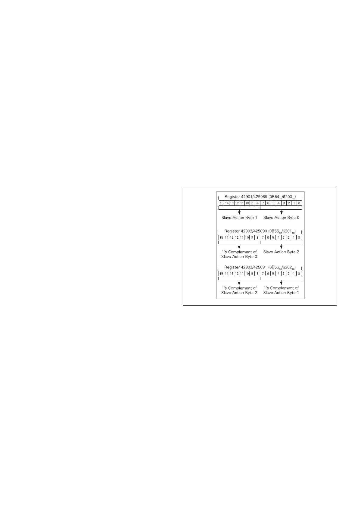
A set of registers is reserved for the control protocol.
They begin at register 42901/425089 (0B54
16
/6200
16
) and
extend through 42903/425091 (0B56
16
/6202
16
). These three
registers are written with a ‘slave action number’ and its
1’s complement using function code 16 (10
16
). The current
‘slave action numbers’, their support being product depen-
dent, are listed in Table 7. The format of the data is shown
in Figure 14. These three registers, and only these three
registers, must be written in one Modbus transaction.
Figure 14. Control of Product Data Format
If the ‘slave action number’ and it 1’s complement are
valid, the MCAM issues the ‘slave action’ control command
to the product. If the slave action request is successfully
acknowledged by the product, the MCAM returns a normal
function code 16 (10
16
) response to the Modbus master.
The Modbus master may further determine if the product
completed the slave action function successfully by interro-
gating the product, for example, by reading its status.
If the product does not acknowledge the slave action
request, the MCAM returns an exception code 04. If the
‘slave action number’ and its 1’s complement are invalid,
the MCAM responds to the Modbus master with a data
value illegal exception code 03. Refer to a later section
entitled “Exception codes.”
Date and time registers
Access to date and time registers provide the opportu-
nity for a Modbus master to set up and/or read real-time
clock information within an Eaton product. Eight registers,
beginning at register number 402921 (i.e., holding regis-
ter address 0B68
16
), are reserved for this information, as
defined in Table 8. Registers are read using function code
03 or 04 and written using function code 16 (10
16
).
Energy format
Energy objects in the MCAM are supported in two-register
fixed point object format and a four-register power/mantissa
format. These objects do not support IEEE floating point
format.
The two-register format is presented in units of kilowat-
thours and is valid for products reporting energy in wat-
thours
or kilowatthours only. Products reporting in units greater
than kilowatthours (for example, megawatthours) could
not guarantee consistent kilowatthour resolution up to and
through their
rollover values.
All products reporting energy (independent of energy units)
support the energy objects occupying four registers—
Register 3 through Register 0. Register 3 is the high order
register and Register 0 is the low order register.
Register 3 high byte contains a value corresponding to
engineering units (power of 10 signed exponent). Register
3 low byte contains a mantissa multiplier value (power of 2
signed exponent).
Register 2 through Register 0 contains a 48-bit energy man-
tissa in units of watthours. Net and total energy objects are
signed values. All other energy objects are unsigned values.
The data format of these four registers is given in Figure 15.
Figure 15. Four-Register Energy Data Format
Supported diagnostic sub-functions
It is possible to obtain diagnostics from the MCAM or an
attached product using function code 08. Refer to Table 9.
Exception codes
Under certain circumstances, the MCAM will return an
exception code.
If the function in the query is not supported by the
MCAM, exception code 01 is returned in the response
If the data (object) register is illegal, exception code 02 is
returned in
the response
If the data in the query is illegal, exception code 03 is
returned
If the attached product fails (usually a timeout), exception
code 04 is returned
In certain circumstances, an exception code 05 (NAK) is
returned
If the MCAM cannot perform the requested function,
exception code 07 (NAK) is returned
If only a partial register is used in the query, exception
code 84 is returned
9
EATON CORPORATION www.eaton.com
Effective December 2010
Instructional Leaflet IL01301034E
Table 4. Modbus Register Map in Register Number Order
Objects (Complete List)
Units
Modbus Register Number Modbus Register Address
FP Scale
Factor
Modbus Products
Name Numeric
IEEE
Float
Fixed
Point (FP)
IEEE Float
(Hex)
Fixed Point
(FP) (Hex)
Series
NRX
520M
Series
NRX
1150
Status cause
a
Primary 404609 or 406145 hi byte 1200 or 1800 hi byte x x
Secondary 404609 or 406145 lo byte 1200 or 1800 lo byte x x
Cause 404610 or 406146 1201 or 1801 x x
Current I
A
A 404611 406147 1202 1802 10 x x
I
B
A 404613 406149 1204 1804 10 x x
I
C
A 404615 406151 1206 1806 10 x x
I
G
A 404617 406153 1208 1808 10 x x
I
N
A 404619 406155 120A 180A 10 x x
L-L voltage V
AB
V 404623 406159 120E 180E 10 x
V
BC
V 404625 406161 1210 1810 10 x
V
CA
V 404627 406163 1212 1812 10 x
L-N voltage V
AN
V 404631 406167 1216 1816 10 x
V
BN
V 404633 406169 1218 1818 10 x
V
CN
V 404635 406171 121A 181A 10 x
Peak current Peak I
A
demand A 404641 406177 1220 1820 10 x
Peak I
B
demand A 404643 406179 1222 1822 10 x
Peak I
C
demand A 404645 406181 1224 1824 10 x
Power Real 3-phase
(power)
W 404651 406187 122A 182A 1 x
Reactive 3-phase
(power)
VAR 404653 406189 122C 182C 1 x
Apparent
3-phase (power)
VA 404655 406191 122E 182E 1 x
Power factor Apparent pf 404659 406195 1232 1832 100 x
ote:N Objects are two registers in length unless specified otherwise.
a
The primary and secondary codes are mapped to the high and low bytes, respectively, of registers 404609 (1200
16
) and 406145 (1800
16
). The primary status codes are shown in Table 10. The secondary
status codes are shown in Table 11. The cause-of-status codes are mapped to registers 404610 (1201
16
) and 406146 (1801
16
). The cause-of-status codes are shown in Table 12. The primary/second-
ary and cause-of-status must be read as a single two register object.
b
These numeric entries have specific definitions dependent on the particular Eaton product.
10
EATON CORPORATION www.eaton.com
Instructional Leaflet IL01301034E
Effective December 2010
Modbus Register Map in Register Number Order (continued)
Objects (Complete List)
Units
Modbus Register Number Modbus Register Address
FP Scale
Factor
Modbus Products
Name Numeric
IEEE
Float
Fixed
Point (FP) IEEE Float (Hex)
Fixed Point
(FP) (Hex)
Series
NRX
520M
Series
NRX
1150
Frequency Freq Hz 404661 406197 1234 1834 10 x
Power Peak demand W 404697 406233 1258 1858 1 x
Real 3-phase (power) W 404715 406251 126A 186A 1 x
Power factor pf
b
pf 404717 406253 126C 186C 100 x
Product ID Prod ID 404719 or 406255 126E or 186E x x
Frequency Freq Hz 404721 406257 1270 1870 100 x
(K) Energy Forward KWh N/A 406259 N/A 1872 1 x
Reverse KWh N/A 406261 N/A 1874 1 x
Total
b
KWh N/A 406263 N/A 1876 1 x
Apparent KVAh N/A 406271 N/A 187E 1 x
Energy (four reg.
objects)
Forward Wh N/A 406305 N/A 18A0 1 x
Reverse Wh N/A 406309 N/A 18A4 1 x
Total
b
Wh N/A 406313 N/A 18A8 1 x
Apparent VAh N/A 406329 N/A 18B8 1 x
ote:N Objects are two registers in length unless specified otherwise.
a
The primary and secondary codes are mapped to the high and low bytes, respectively, of registers 404609 (1200
16
) and 406145 (1800
16
). The primary status codes are shown in Table 10. The secondary
status codes are shown in Table 11. The cause-of-status codes are mapped to registers 404610 (1201
16
) and 406146 (1801
16
). The cause-of-status codes are shown in Table 12. The primary/second-
ary and cause-of-status must be read as a single two register object.
b
These numeric entries have specific definitions dependent on the particular Eaton product.
11
EATON CORPORATION www.eaton.com
Effective December 2010
Instructional Leaflet IL01301034E
Table 5. Modbus Register Map in Functional Number Order
Objects (Complete List)
Units
Modbus Register Number Modbus Register Address
FP Scale
Factor
Modbus Products
Name Numeric
IEEE
Float
Fixed
Point (FP) IEEE Float (Hex)
Fixed Point (FP) (Hex)
Series
NRX
520M
Series
NRX
1150
Product ID Prod ID 404719 or 406255 126E or 186E x x
Status cause
a
Primary
404609 or 406145 hi byte 1200 or 1800 hi byte
x x
Secondary
404609 or 406145 lo byte 1200 or 1800 lo byte
x x
Cause 404610 or 406146 1201 or 1801 x x
Current I
A
A 404611 406147 1202 1802 10 x x
I
B
A 404613 406149 1204 1804 10 x x
I
C
A 404615 406151 1206 1806 10 x x
I
G
A 404617 406153 1208 1808 10 x x
I
N
A 404619 406155 120A 180A 10 x x
Peak I
A
demand A 404641 406177 1220 1820 10 x
Peak I
B
demand A 404643 406179 1222 1822 10 x
Peak I
C
demand A 404645 406181 1224 1824 10 x
L-L voltage V
AB
V 404623 406159 120E 180E 10 x
V
BC
V 404625 406161 1210 1810 10 x
V
CA
V 404627 406163 1212 1812 10 x
L-N voltage V
AN
V 404631 406167 1216 1816 10 x
V
BN
V 404633 406169 1218 1818 10 x
V
CN
V 404635 406171 121A 181A 10 x
Frequency Freq Hz 404661 406197 1234 1834 10 x
Freq Hz 404721 406257 1270 1870 100 x
Power
Real 3-phase
(power)
W 404715 406251 126A 186A 1 x
Peak demand
W 404697 406233 1258 1858 1 x
ote:N All objects are two registers in length unless specified otherwise.
a
The primary and secondary codes are mapped to the high and low bytes, respectively, of registers 404609 (1200
16
) and 406145 (1800
16
). The primary status codes are shown in Table 10. The secondary
status codes are shown in Table 11. The cause-of-status codes are mapped to registers 404610 (1201
16
) and 406146 (1801
16
). The cause-of-status codes are shown in Table 12. The primary/second-
ary and cause-of-status must be read as a single two register object.
b
These numeric entries have specific definitions dependent on the particular Eaton product.
12
EATON CORPORATION www.eaton.com
Instructional Leaflet IL01301034E
Effective December 2010
Modbus Register Map in Functional Number Order (continued)
Objects (Complete List)
Units
Modbus Register Number Modbus Register Address
FP Scale
Factor
Modbus Products
Name Numeric
IEEE
Float
Fixed
Point (FP)
IEEE Float
(Hex) Fixed Point (FP) (Hex)
Series
NRX
520M
Series
NRX
1150
Power Real 3-phase
(power)
W 404651 406187 122A 182A 1 x
Reactive
3-phase
VAR 404653 406189 122C 182C 1 x
Apparent
3-phase
VA 404655 406191 122E 182E 1 x
Power factor pf
b
pf 404717 406253 126C 186C 100 x
Apparent pf 404659 406195 1232 1832 100 x
(K) Energy Forward KWh N/A 406259 N/A 1872 1 x
Reverse KWh N/A 406261 N/A 1874 1 x
Total
b
KWh N/A 406263 N/A 1876 1 x
Apparent KVAh N/A 406271 N/A 187E 1 x
Energy (four reg.
objects)
Forward Wh N/A 406305 N/A 18A0 1 x
Reverse Wh N/A 406309 N/A 18A4 1 x
Total
b
Wh N/A 406313 N/A 18A8 1 x
Apparent VAh N/A 406329 N/A 18B8 1 x
ote:N All objects are two registers in length unless specified otherwise.
a
The primary and secondary codes are mapped to the high and low bytes, respectively, of registers 404609 (1200
16
) and 406145 (1800
16
). The primary status codes are shown in Table 10. The secondary
status codes are shown in Table 11. The cause-of-status codes are mapped to registers 404610 (1201
16
) and 406146 (1801
16
). The cause-of-status codes are shown in Table 12. The primary/second-
ary and cause-of-status must be read as a single two register object.
b
These numeric entries have specific definitions dependent on the particular Eaton product.
Table 6. MCAM Configuration Registers
Register Definition R/W
Modbus Register
10
Number Modbus Register Address
16
Number of Registers
1
0
Low High Low High
Mapped block of registers configuration R/W 41001 420481 03E8 5000 100
Mapped block of registers data R 41201 420737 04B0 5100 4 * 100
Invalid object access configuration R/W 42001 425345 07D0 6300 1
Floating Pt data word order configuration R/W 42002 425346 07D1 6301 1
Fixed Pt data word order configuration R/W 42003 425347 07D2 6302 1
Supervisory control query R/W 42901 425089 0B54 6200 3
Date and time registers R/W 42921 0B68 8
13
EATON CORPORATION www.eaton.com
Effective December 2010
Instructional Leaflet IL01301034E
Table 7. Control ‘Slave Action Number’ Definitions
Control
Group Definition Byte 2 Byte 1 Byte 0
Reset Reset trip 0 0 2
Reset (peak) demand-watts 0 0 4
Reset (synchronize) demand watts window 0 0 64 (40
16
)
Snapshot command 0 0 128 (80
16
)
Reset (peak) demand-currents 0 1 1
Reset all min./max. values 0 1 4
Unlock waveform buffer (clear upload-in-
progress)
0 1 5
Reset min./max. currents 0 1 13
Reset min./max. PF-apparent 0 1 16
Circuit
breaker open-
close
Open request 1 0 0
Close request 1 0 1
Enable Maintenance Mode 1 0 8
Disable Maintenance Mode 1 0 9
Table 8. Date and Time Register Definitions
Definition
Register Number
(Decimal)
Register Address
(Hexadecimal)
Data Range
(Decimal)
Month 402921 0B68 1–12
Day 402922 0B69 1–31
Year 402923 0B6A
Day of week 402924 0B6B 1=Sunday...7=Saturday
Hour 402925 0B6C 0–23
Minute 402926 0B6D 0–59
Second 402927 0B6E 0–59
1/100th second 402928 0B6F 0–99
Table 9. Diagnostic Sub-Function Numbers
Sub-Function
No. (Decimal) Name
0 Echo query
1 Restart communications
4 Force listen
10 Clear MCAM/slave product counters
11 Modbus UART bus message count
12 Modbus UART communication error count
13 MCAM exception error count
14 MCAM message count
15 MCAM no response count
16 MCAM NAK count
17 MCAM busy count
18 Modbus UART over run error count
20 Clear Modbus UART counters
21 Slave product checksum error count
22 Slave product over run count
23 Modbus UART framing error count
24 Modbus UART noise error count
25 Modbus UART parity error count
26 MCAM firmware version & rev
27 MCAM firmware month & day
28 MCAM firmware year
29 Reset MCAM block-of-registers
Table 10. Primary Status Code Definitions
Code Definition
0 Unknown
1 Open
2 Closed
3 Tripped
4 Alarmed
13 Pickup
Table 11. Secondary Status Code Definitions
Code Definition
0 Unknown
3 Test mode
7 Powered up
8 Alarm
14
EATON CORPORATION www.eaton.com
Instructional Leaflet IL01301034E
Effective December 2010
Table 12. Cause-of-Status Code Definitions
Code Definition Code Definition
0 Unknown 65 Reverse power
1 Normal operating mode 66 Fixed instantaneous phase overcurrent #2
3 Instantaneous phase overcurrent 67 Reverse phase
11 Overvoltage 68 Reverse sequence
12 Undervoltage 69 Phase current loss
15 Underfrequency 71 Alarm active
16 Overfrequency 72 Bad frame
17 Current unbalance 73 Phase currents near pickup
18 Voltage unbalance 75 Making current release
19 Apparent power factor 76 Fixed instantaneous phase overcurrent #3
26 Power demand 77 Set points error
27 VA demand 78 Over-temperature
30 Total harmonic distortion 80 Long delay neutral overcurrent
31 Operations count 82 Historical data
33 Control via communications 84 Ground fault (instantaneous or delay)
37 Coil supervision 85 Earth fault (instantaneous or delay)
39 RAM error 146 Frequency out of range
43 EEROM error 148 Check auxiliary switch
46 Watchdog 149 Overcurrent
61 Long delay phase overcurrent 153 Maintenance mode
62 Short delay phase overcurrent 154 Breaker mech. fault
63 Fixed instantaneous phase
overcurrent #1
156 Disconnect position
64 Bad/missing rating plug 157 Trip Actuator
Section 8: Troubleshooting
The following are the most common issues experienced
with the installation of a Series NRX Modbus communica-
tions adapter module. If you have additional questions or
need further information and/or instructions, please contact
your local Eaton
representative or visit www.eaton.com
.
Observation 1—Status LED not flashing
Action—Verify proper input power to module connectors.
Observation 2—Status LED flashing green, but module
does not change state in response to master command
requests
Action—Verify correct module address.
Action—Verify communication cable
is connected correctly from master
to module.
15
EATON CORPORATION www.eaton.com
Effective December 2010
Instructional Leaflet IL01301034E
Effective December 2010
Disclaimer of warranties and limitation of liability
The information, recommendations, descriptions, and safety
notations in this document are based on Eaton Corporation’s
(“Eaton”) experience and judgment, and may not cover all
contingencies. If further information is required, an Eaton sales
office should be consulted.
Sale of the product shown in this literature is subject to the
terms and conditions outlined in appropriate Eaton selling poli-
cies or other contractual agreement between Eaton and the
purchaser.
THERE ARE NO UNDERSTANDINGS, AGREEMENTS,
WARRANTIES, EXPRESSED OR IMPLIED, INCLUDING
WARRANTIES OF FITNESS FOR A PARTICULAR PURPOSE
OR MERCHANTABILITY, OTHER THAN THOSE SPECIFICALLY
SET OUT IN ANY EXISTING CONTRACT BETWEEN THE
PARTIES. ANY SUCH CONTRACT STATES THE ENTIRE
OBLIGATION OF EATON. THE CONTENTS OF THIS
DOCUMENT SHALL NOT BECOME PART OF OR MODIFY
ANY CONTRACT BETWEEN THE PARTIES.
In no event will Eaton be responsible to the purchaser or user
in contract, in tort (including negligence), strict liability, or other-
wise for any special, indirect, incidental, or consequential dam-
age or loss whatsoever, including but not limited to damage
or loss of use of equipment, plant or power system, cost of
capital, loss of power, additional expenses in the use of exist-
ing power facilities, or claims against the purchaser or user by
its customers resulting from the use of the information, recom-
mendations, and descriptions contained herein.
The information contained in this manual is subject to change
without notice.
Eaton Corporation
Electrical Group
1000 Cherrington Parkway
Moon Township, PA 15108
United States
877-ETN-CARE (877-386-2273)
Eaton.com
© 2010 Eaton Corporation
All Rights Reserved
Printed in USA
Publication No. IL01301012E
December 2010
PowerChain Management is a registered
trademark of Eaton Corporation.
All other trademarks are property of their
respective owners.
Gültig ab Dezember 2010
Ersetzt September 2010
IL01301034EH02
Montageanweisung IL01301034E
Montageanweisung für das Modbus
Kommunikationsadaptermodul (MCAM)
IZM91 und IZMX16
WARNUNG
(1) DIE INSTANDHALTUNG DARF NUR DURCH ENTSPRECHEND
ELEKTRONTECHNISCH QUALIFIZIERTES PERSONAL ERFOLGEN.
(2) VOR BEGINN DER ARBEITEN MUSS DER SPANNUNGSFREIE
ZUSTAND DER SCHALTANLAGE HERGESTELLT UND WÄHREND DER
ARBEITEN SICHERGESTELLT SEIN.
(3) SCHALTER IN AUSFAHRTECHNIK MÜSSEN IN TRENNSTELLUNG
GEFAHREN WERDEN.
(4) DIE SCHALTER SIND AUF AUS ZU STELLEN UND DER FEDERSPEICHER
IST ZU ENTSPANNEN.
BEIM BETRIEB ELEKTRISCHER GERÄTE STEHEN ZWANGSLÄUFIG
BESTIMMTE TEILE DIESER GERÄTE UNTER GEFÄHRLICHER
SPANNUNG.
UNSACHGEMÄSSER UMGANG MIT DIESEN GERÄTEN KANN
DESHALB ZU TOD ODER SCHWEREN KÖRPERVERLETZUNGEN SOWIE
ERHEBLICHEN SACHSCHÄDEN FÜHREN.
WARNUNG
BEACHTEN SIE BEI INSTANDHALTUNGSMASSNAHMEN AN DIESEM
GERÄT ALLE IN DIESER AWA UND AUF DEM PRODUKT SELBST
AUFGEFÜHRTEN HINWEISE. DIE FÜNF SICHERHEITSREGELN SIND
EINZUHALTEN:
FREISCHALTEN
GEGEN WIEDEREINSCHALTEN SICHERN
SPANNUNGSFREIHEIT FESTSTELLEN
ERDEN UND KURZSCHLIESSEN
BENACHBARTE, UNTER SPANNUNG STEHENDE TEILE ABDECKEN
ODER ABSCHRANKEN
DAS GERÄT IST VOM NETZ ZU TRENNEN. ES DÜRFEN NUR VOM
HERSTELLER ZUGELASSENE ERSATZTEILE VERWENDET WERDEN.
DIE VORGESCHRIEBENEN WARTUNGSINTERVALLE SOWIE
DIE ANWEISUNGEN FÜR REPARATUR UND AUSTAUSCH SIND
UNBEDINGT EINZUHALTEN, UM SCHÄDEN AN PERSONEN UND
ANLAGEN ZU VERMEIDEN.
Abschnitt 1: Allgemeine Informationen
Das IZM91 und IZMX16 ModbusT
Kommunikationsadaptermodul (Abb.1) ist ein Zubehörteil,
welches als Kommunikationseinheit zusammen mit
einer kompatiblen IZM91 und IZMX16 Auslöseeinheit/
Leistungsschalter in einem übergeordneten
Kommunikationsnetzwerk verwendet wird (Abb.2). Der Typ
des Moduls lautet MCAM.
Das MCAM kommuniziert über das Modbus RTU (Remote
Terminal Unit) Protokoll mit einem Master im Modbus-
Netzwerk. Alle Information werden mittels fest zugewie-
senen Registern über das MCAM zwischen dem Modbus-
Master und der Auslöseeinheit ausgetauscht.
Abbildung 1. IZM91 und IZMX16 Modbus-
Kommunikationsadaptermodul Module
2
EATON CORPORATION www.eaton.com
Montageanweisung IL01301034E
Gültig ab Dezember 2010
Abbildung 2. Modbus- Kommunikationsadaptermodule in
einem Modbus-Netzwerk
Das Modbus-Kommunikationsadaptermodul ist ein
reines Slave-Gerät und benötigt daher einen Master
zu Initiierung der Steuerbefehle. Jedes Modbus-
Kommunikationsadaptermodul enthält:
Schalter öffnen/schließen/zurücksetzen
Auswahl an der Auslöseeinheit zwischen Quelle/
Erdschluss (wenn verfügbar)
Eine blinkende Statusleuchte zeigt an, dass das Modul
aktiv ist
Steckbrücke zur Aktivierung/Deaktivierung der Modbus-
Kommunikation, um eine Fernsteuerung zum Ein-/
Ausschalten des Leistungsschalters zu ermöglichen
DIN-Hutschienenmontage (Minimalanforderungen der
Hutschiene: Höhe: 11 mm, Breite: 28 mm)
Die Eingangsleistung des Moduls beträgt 24 Vdc
Die Installation, Bedienung und Instandhaltung des
Modbus- Kommunikationsadaptermoduls ist von qualifi-
zierten, eingewiesenen Personen durchzuführen. Diese
Anleitung deckt nicht alle möglichen Eventualitäten, die
während Installation, dem Betrieb oder der Instandhaltung
auftreten können, oder alle Details und Variationen der
beschriebenen Betriebsmittel ab.
Kommunikations-
Netzwerk
Master
Gerät
MCAM
Module
1
MCAM
Module
2
MCAM
Module
3
IZM91 & IZMX16
Leistungsschalter
IZM91 & IZMX16
Leistungsschalter
IZM91 & IZMX16
Leistungsschalter
Abschnitt 2: Installation eines Modbus
Kommunikationsbaugruppe Adaptermoduls
Die folgenden Schritte zeigen ausschließlich die
Vorgehensweise zur Installation eines IZM91 und IZMX16
Modbus-Kommunikationsadaptermoduls in einer ausziehba-
ren Konfiguration eines Leistungsschalters. Bei fest einge-
bauten Leistungsschaltern wird eine separate Konfiguration
zur DINHutschienenmontage bevorzugt. Wenden Sie sich
hierzu bitte an unseren Kundendienst, um weiterführende
Informationen zu erhalten.
Halten Sie die folgenden Werkzeuge bereit:
#T-15 Torx
Kleiner Schlitzschraubendreher
Bei ausziehbaren Leistungsschaltern werden die
sekundären Klemmenblöcke sowie das Modbus-
Kommunikationsadaptermodul auf einer DIN-Hutschiene
über der Front der ausziehbaren Kassette des
Leistungsschalters montiert. Das Modul ist so konzipiert,
dass es die vier Klemmenblöcke (insgesamt acht Kontakte)
der Sekundärkontakte 19–26 hinzufügt bzw. ersetzt.
Siehe Hauptschaltplan in der Bedienungsanleitung des
Leistungsschalters AWB1230-1628. Weitere Informationen
hinsichtlich der Installation und/oder Ausbau der sekundären
Klemmenblöcke und mehr, welches in diesem Abschnitt
enthalten ist, finden Sie unter AWA1230-2610.
Fahren Sie mit den folgenden sieben Schritten fort:
Schritt 1: Entfernen Sie mit einem T-15 Torx-
Schraubendreher die vier Befestigungsschrauben, welche
den Ausrichthalterung des Klemmenblocks fixieren.
Abbildung 3. Schritt 1
3
EATON CORPORATION www.eaton.com
Gültig ab Dezember 2010
Montageanweisung IL01301034E
Schritt 2: Schieben Sie nun die Ausrichthalterung zwischen
einem beliebigen Klemmenblock vorsichtig nach außen und
legen Sie diesen nun mit dem gesamten Montagezubehör
für den späteren Wiedereinbau, nach der Installation des
Kommunikationsadaptermoduls auf der DIN-Hutschiene,
beiseite.
Abbildung 4. Schritt 2
Schritt 3: Entfernen Sie nun den Klemmenblock der
Position 19/20, indem Sie einen kleinen Schraubendreher
in den zurückgesetzten Bereich an der oberen Front des
Klemmenblocks, wie abgebildet, stecken und diesen nun
vorsichtig nach unten drücken, um den Klemmenblock aus-
zurasten und diesen von der DINHutschiene entfernen zu
können.
Abbildung 5. Schritt 3
Schritt 4: Wiederholen Sie die Vorgehensweise von Schritt
3, um die Klemmenblöcke an den Positionen 21/22, 23/24
und 25/26 zu entfernen.
nmerkung:A Die zusätzliche Befestigungsschraube der DIN-
Hutschiene, die sich im Zwischenraum der vier Klemmenblöcke
befindet, muss möglicherweise entfernt werden, damit der Erdungs-
Federstift (Pogo-Pin) eine gute Verbindung mit der DIN-Hutschiene hat.
Abbildung 6. Schritt 4
Schritt 5: Kippen Sie nun das Kommunikationsmodul nach
vorne, und setzen Sie es auf der DIN-Hutschiene auf und
rasten Sie es dann vollständig auf der DIN-Hutschiene auf.
Abbildung 7. Schritt 5
Schritt 6: Schieben Sie nun die Ausrichteklammer des
Klemmenblocks wieder in Position. Überprüfen Sie die
Unterseite der Ausrichthalterung, dass die Zahnung
der Klammer jeden einzelnen Klemmenblock trennt,
bevor Sie die Ausrichthalterung installieren. Ist die
Ausrichthalterung ordnungsgemäß eingebaut, soll-
te zwischen der Zahnung der Ausrichteklammer
immer nur ein Klemmenblock sichtbar sein.
Befestigen Sie die Ausrichthalterung mit den vier zuvor
entfernten Befestigungsschrauben. Ziehen Sie die vier
Befestigungsschrauben von Hand fest.
Abbildung 8. Schritt 6
Befestigungsschraube
Schritt 7: Die Installation ist somit abgeschlossen und das
Kommunikationsmodul sollte wie nebenstehend abgebildet
montiert sein. Das Modul kann nun, unter Berücksichtigung
der in Abschnitt 3 aufgeführten Informationen, verdrahtet
werden.
Abbildung 9. Schritt 7
Abschnitt 3: Grundlegende Verdrahtung
des Modbus RS-485 Netzwerks
Die folgenden vereinfachten Regeln gelten für ein beste-
hendes System, welches aus einer Kabelverbindung
zwischen dem Master und den Slaves besteht (Abb.22).
Beachten Sie bitte bei komplexeren Systemkonfigurationen
die Modbus RTU Standard-Verdrahtungsvorgaben für das
RS-485 Netzwerk.
1. Das empfohlene Modbus Kabel ist ein Twisted-Pair Kabel
(Litze mit 24AWG und 7 x 32 Leitern mit PVC Isolierung),
welches eine Abschirmfolie aus Aluminium/Mylar und
eine Beilauflitze enthält.
2. Die maximale Systemleistung beträgt 1,2 km Kabellänge
und 247 Teilnehmer am Modbus RTU-Netzwerk.
3. Gewährleisten Sie, dass das Twisted- Pair Kabel für die
Anwendung als Modbus RTU-Netzwerkkabel geeignet
ist. Verwenden Sie das abgeschirmte Twisted-Pair Kabel,
um jeden Slave in das Modbus RTU-Netzwerk einzu-
schleifen („daisychain“ Verkettung). Die Polarität der
beiden Leiter ist müssen unbedingt beachtet werden.
Abschnitt 4: Anschlüsse des Modbus Kom-
munikationsbaugruppe Adaptermoduls
WARNUNG
BEI DER INSTALLATION, DEM BETRIEB UND DER WARTUNG
DIESES GERÄTES MÜSSEN STETS ALLE ANZUWENDENDEN
SICHERHEITSRICHTLINIEN, -NORMEN UND -GESETZE STRIKT
EINGEHALTEN WERDEN. NICHTBEACHTUNG KANN ZU
SACHSCHÄDEN, VERLETZUNGEN ODER TOD FÜHREN.
Besonderheiten zur Installation finden Sie in den
Schaltplänen in Abb.3 und Abb.4 auf page 3 und
page 3 ff. sowie den Anschlussbelegungen in Tabelle
1 (Versorgungsanschlüsse) und Tabelle 2 (Modbus-
Anschlüsse).
Tabelle 1. Anschlussbelegung
Spannungsversorgunga
a
Pin Number Input Signal
1 24 Vdc +
2 24 Vdc
3 Steuersignal Masse
4 Steuersignal „Öffnen”
5 Steuersignal „Schließen”
a
Die Spannungsversorgung des Moduls ist über einen 5-poligen Steckverbinder. Leistungsbedarf
ist 24 Vdc, 10 Watt.
Tabelle 2. Modbus Anschlussbelegung
ab
1 RS-485 Netzwerk-B (nicht-invertierend)
2 RS-485 Netzwerk-A (invertierend)
3 Masse
4 Schirm
a
Dieser 4-polige Anschluss ist die Schnittstelle zum Modbus-Netzwerk.
b
Verbinden Sie den Kabelschirm nur am Master mit Masse. Wenn Geräte prioritätsverkettet sind,
verbinden Sie die Schirme miteinander.
4
EATON CORPORATION www.eaton.com
Montageanweisung IL01301034E
Gültig ab Dezember 2010
Pin Nummer Eingangssignal
  • Page 1 1
  • Page 2 2
  • Page 3 3
  • Page 4 4
  • Page 5 5
  • Page 6 6
  • Page 7 7
  • Page 8 8
  • Page 9 9
  • Page 10 10
  • Page 11 11
  • Page 12 12
  • Page 13 13
  • Page 14 14
  • Page 15 15
  • Page 16 16
  • Page 17 17
  • Page 18 18
  • Page 19 19
  • Page 20 20
  • Page 21 21
  • Page 22 22
  • Page 23 23
  • Page 24 24
  • Page 25 25
  • Page 26 26
  • Page 27 27
  • Page 28 28
  • Page 29 29
  • Page 30 30
  • Page 31 31
  • Page 32 32
  • Page 33 33
  • Page 34 34

Eaton Series NRX Installation Instructions Manual

Category
Networking
Type
Installation Instructions Manual

Ask a question and I''ll find the answer in the document

Finding information in a document is now easier with AI

in other languages