Page is loading ...
Page is loading ...
Page is loading ...

4
ENGLISH
(Original instructions)
Intended use
Your Stanley Fat Max Chop Saw has been designed for the
cutting of variously shaped steel materials. This tool is
intended for professional and private, non professional users..
Safety instructions
General power tool safety warnings
@
Warning! When using power tools, always
observe the safety regulations applicable in your
country to reduce the risk of re, electric shock
and personal injury.
u Read all of this manual carefully before using the
appliance.
u The intended use is described in this manual. The use of
any accessory or attachment or the performance of any
operation with this appliance other than those
recommended in this instruction manual may present a
risk of personal injury.
u Retain this manual for future reference.
1. Keep work area clean
Cluttered areas and benches can cause accidents.
2. Consider work area environment
Do not expose the tool to rain. Do not use the tool in damp or
wet conditions. Keep the work area well lit (250 - 300 Lux). Do
not use the tool where there is a risk of causing re or
explosion, e.g. in the presence of ammable liquids and
gases.
3. Guard against electric shock
Prevent body contact with earthed surfaces (e.g. pipes,
radiators, cookers and refrigerators). When using the tool
under extreme conditions (e.g. high humidity, when metal
swarf is being produced, etc.), electric safety can be further
improved by using a highsensitivity 30 mA Residual Current
Device (RCD).
4. Keep other persons away
Do not let persons, especially children, not involved in the
work touch the tool or the extension cord and keep them away
from the work area.
5. Store idle tools
When not in use, tools must be stored in a dry place and
locked up securely, out of reach of children.
6. Do not force the tool
It will do the job better and safer at the rate for which it was
intended.
7. Use the right tool
Do not force small tools to do the job of a heavy duty tool. Do
not use tools for purposes not intended; for example do not
use circular saws to cut tree limbs or logs.
8. Dress properly
Do not wear loose clothing or jewellery, as these can be
caught in moving parts. Wear protective hair covering to keep
long hair out of the way. When working outdoors, preferably
wear suitable gloves and non-slip footwear.
9. Use protective equipment
Always use safety glasses. Use a face or dust mask whenever
the operations may produce dust or ying particles. If these
particles might be considerably hot, also wear a heat-resistant
apron. Wear ear protection at all times. Wear a safety helmet
at all times.
10. Connect dust extraction equipment
If devices are provided for the connection of dust extraction
and collection facilities, ensure that these are connected and
properly used.
11. Do not abuse cord
Never carry the tool by its cord. Never pull the cord to
disconnect from the socket. Keep the cord away from heat, oil
and sharp edges.
12. Secure workpiece
Use clamps or a vice to hold the workpiece. It is safer and it
frees both hands to operate the tool.
13. Do not overreach
Keep proper footing and balance at all times.
14. Maintain tools with care
Keep cutting tools sharp and clean for better and safer
performance. Follow instruction for lubricating and changing
accessories. Inspect tool cords periodically and if damaged
have them repaired by an authorized service facility. Inspect
extension cords periodically and replace if damaged. Keep
handles dry, clean and free from oil and grease.
15. Disconnect tool
Switch off and wait for the tool to come to a complete standstill
before leaving it unattended. Unplug the tool when not in use,
before changing any parts of the tools, accessories or
attachments and before servicing.

5
ENGLISH
(Original instructions)
16. Remove adjusting keys and wrenches
Always check that adjusting keys and wrenches are removed
from the tool before operating the tool.
17. Avoid unintentional starting
Do not carry the tool with a nger on the switch. Be sure that
the tool is switched off before plugging in.
18. Use outdoor extension cables
Before use, inspect the extension cable and replace if
damaged. When using the tool outdoors, only use extension
cables intended for outdoor use and marked accordingly.
19. Stay alert
Watch what you are doing, use common sense and do not
operate the tool when you are tired.
20. Check for damaged parts
Before use, carefully check the tool and mains cable for
damage. Check for misalignment and seizure of moving
parts, breakage of parts, damage to guards and switches and
any other conditions that may affect its operation. Ensure that
the tool will operate properly and perform its intended function.
Do not use the tool if any part is damaged or defective. Do not
use the tool if the switch does not turn it on and off. Have any
damaged or defective parts replaced by an authorised Black
and Decker repair agent. Never attempt any repairs yourself.
21. Warning!
The use of any accessory or attachment or performance of
any operation with this tool other than those recommended in
this instruction manual may present a risk of personal injury.
22. Have your tool repaired by a qualied person
This tool is in accordance with the relevant safety regulations.
Have your tool repaired by an authorised Black and Decker
repair agent. Repairs should only be carried out by qualied
persons using original spare parts; otherwise this may result in
considerable danger to the user.
Additional safety instructions for chopsaws
u Always wear regular working gloves while operating this
tool.
u Keep hands away from the cutting disc. Never cut
workpieces that require manual action closer than 15 cm
from the rotating cutting disc.
u Do not cut workpieces less than 1.2 mm in thickness when
using the cutting disc supplied with this tool.
u Do not operate this tool without guards in place.
u Do not perform any operation freehand. Use the material
clamp to clamp the workpiece securely.
u Never reach in the back of the cutting disc.
u Always position the tool on a at, stable surface that is
well maintained and free of loose materials, e.g. chips and
cut-offs.
u Before using, inspect the cutting disc for cracks or aws.
Discard the cutting disc if a crack or aw is evident.
u Make sure the cutting disc is not contacting the workpiece
before the tool is switched on.
u In operation, avoid bouncing the cutting disc or giving it
rough treatment. If this occurs, stop the tool and inspect
the cutting disc.
u Do not operate the tool while standing in line with the
cutting disc. Keep other persons away from the work area.
u Be aware of cutting chips and the material being cut. They
may be sharp and hot. Allow cut off parts to cool before
handling.
u The spark deector becomes hot during use. Avoid
touching or adjusting the spark deector immediately after
operation.
u Switch off the tool and wait for the cutting disc to stop
before moving the workpiece or changing the settings.
u After switching off, never attempt to stop the cutting disc
by pressing against the side of the disc.
u Do not use cutting uids. These uids could ignite or
cause electrical shock.
u Check that the workpiece is properly supported.
u Use the cutting discs recommended by the manufacturer
only. Never use circular saw blades or any other types of
toothed blades.
u The max. allowable speed of the cutting disc must always
be equal to or greater than the no-load speed of the tool
specied on the nameplate.
u Do not use cutting discs that do not conform to the
dimensions stated in the technical data.
u Only use cutting discs that conform to EN12413.
u Ensure that the cutting disc is mounted correctly before
use.
u Let the tool run at no-load in a safe position for at least 30
seconds. If there is a considerable vibration or if any other
defect occurs, stop the tool and check it to determine the
cause.
u Do not use cutting discs for side grinding.
u Do not cut concrete, brick, tile or ceramic materials.
u Do not cut wood, plastic or synthetic materials.
u Do not cut cast-iron materials.
u Never cut magnesium materials.
u Do not cut electrically live material.
u Use this tool in a well-ventilated area. Do not operate the
tool near ammable liquids, gases or dust. Sparks or hot
chips from cutting or arcing motor brushes may ignite
combustible materials.
u Regularly clear the ventilation slots when working in dusty
conditions. If it should become necessary to clean the
slots, remember to unplug the tool rst.

6
ENGLISH
(Original instructions)
u Always store cutting discs well-protected and in a dry
place, out of reach of children.
u Warning!Use of this tool can generate dust containing
chemicals known to cause cancer, birth defects or other
reproductive harm. Use appropriate respiratory protection.
Warning! Only use a chop saw wheel with a
maximum thickness of 3 mm and a maximum
diameter of 355mm.
Warning! The cutting wheel will continue to rotate after the
tool has been switched off.
u Use only reinforced wheels rated 4300 rpm or higher.
u Always wear eye protection, use guards, clamp work in
vise, use proper respiratory protection.
The following factors are of inuence to noise production:
u the material to be cut
u the type of the cutting disc
u the feed force
u Warning!Take appropriate measures for the protection of
hearing.
Residual risks
The following risks are inherent to the use of these
machines:
u injuries caused by touching the rotating parts
u injuries caused by disruption of the cutting disc
These risks are most evident:
u within the range of operation
u within the range of the rotating machine parts
In spite of the application of the relevant safety regulations
and the implementation of safety devices, certain residual
risks cannot be avoided. These are:
u Impairment of hearing.
u Risk of accidents caused by the uncovered parts of the
rotating cutting disc.
u Risk of injury when changing the disc.
u Risk of squeezing ngers when opening the guards.
Electrical safety
#
Your tool is double insulated; therefore no earth
wire is required. Always check that the mains
voltage corresponds to the voltage on the rating
plate. Never attempt to replace the charger unit
with a regular mains plug.
u If the supply cord is damaged, it must be replaced by the
manufacturer or an authorised Stanley Fat Max Service
Centre in order to avoid a hazard.
Voltage drops
Inrush currents cause short-time voltage drops.
Under unfavourable power supply conditions, other
equipment may be affected.
If the system impedance of the power supply is lower
than 0.12 Ω, disturbances are unlikely to occur.
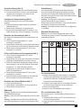
Warning Symbols
The following symbols are found on the tool:
:
Warning! To reduce the risk of injury, the user
must read the instruction manual.
O
Always wear safety goggles.
N
Always wear safety hearing protection.
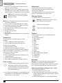
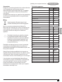
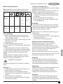
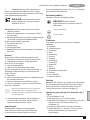
Features
This tool includes some or all of the following features.
A. Lock Chain
B. Spark deector screw
C. Spark deector
D. Base
E. Fence
F. Vice
G. Flat Wrench
H. Crank
I. Vice Lever
J. Cutting disc
K. Guard
L. Spindle Lock
M. Depth Stop Bolt and Locking Nut
N. Trigger Switch
O. Padlock Hole
P. Fence Bolts
Assembly
Warning! Turn off and unplug the tool before making any
adjustments or removing or installing attachments or
accessories. Be sure the trigger switch is in the OFF position.
Do not make any adjustment while the wheel is in motion..
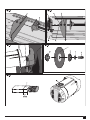
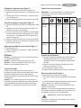
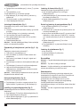
Removing and tting a cutting disc (g. 7 - g 8)
u Push in the spindle lock (L).
u Rotate the cutting disc (J) until it locks.
u Using the at wrench (G), remove the bolt (S) by turning
counterclockwise and then remove the washer (T) and the
retaining ange (U).
u Check that the spacer (R) is in place against the ange.

7
ENGLISH
(Original instructions)
u Replace the cutting disc (J). Make sure that the new disc
is placed onto the spacer (R) in the correct rotational
direction.
u Secure the blade with the retaining ange (U), the washer
(T) and the bolt (S).
u Push in the spindle lock (L).
u Rotate the cutting disc (J) until it locks.
u Using the at wrench (G), tighten the bolt (S) by turning
clockwise.
u Move the guard back down and release the spindle lock
(L).
u Adjust the cutting depth as necessary.
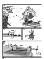
Adjusting the cutting depth (g. 1)
The cutting depth can be adjusted to meet the wear of the
cutting disc.
u Make a dry run with the tool switched off and check for
clearance.
u If adjustment is required, proceed as follows:
u Loosen the lock nut (M) a few turns.
u Turn the depth stop bolt (M) in or out as to achieve the
required cutting depth.
u Tighten the lock nut (M).
Warning: Always adjust the depth stop to its original position
when replacing the cutting disc.
Clamping the workpiece in position (g. 2 - g 4)
The tool is equipped with a vise (F)
u Pull the lever (I) toward the handle (H).
u Push the vise (F) forward until the jaw is almost touching
the workpiece.
u Press the lever (I) toward the jaw until it engages with the
clamp shaft.
u Rotate the handle (H) clockwise and clamp the workpiece
securely.
u To release the workpiece, rotate the handle (H)
counterclockwise.
u To increase the cutting capacity, place a spacer block
under the workpiece. The spacer block should be slightly
narrower than the workpiece.
Warning: Support long workpieces using a piece of wood. Do
not clamp the cut off end.
Quick travel feature (g. 4)
The clamp has a quick travel feature.
u To release the clamp, rotate the handle (H) one or two
turns counterclockwise and pull the lever (I) toward the
handle (H).
Setting the clamping position (g. 5)
The clamping position can be set to match the cutting disc.
u Remove the fence bolts (P) using the at wrench (G).
u Move the fence (E) as required.
u Re-t the fence bolts (P) and tighten them to lock the
fence (E).
Adjusting the angle of cut (g. 6)
The tool can be used for mitre cuts up to 45°.
u Loosen the fence bolts (P) to release the fence (E).
u Set the fence (E) to the required angle. The angle can be
read on the scale (Q).
u Tighten the fence bolts (P) to lock the fence (E).
Checking and adjusting the mitre scale (g. 6)
u Loosen the fence bolts (P) to release the fence (E).
u Pull down the arm and lock it in this position by attaching
the lock chain (A).
u Place a square against the fence (E) and the left side of
the cutting disc creating a perfect 90°. Check that the 0°
marking on the scale (Q) aligns with the marking on the
base (D).
u Tighten the fence bolts (P) to lock the fence (E).
u Remove the lock chain (A) and return the arm to its upper
rest position.
Adjusting the spark deector (g. 1)
u Loosen the screw (B).
u Set the spark deector (C) as appropriate.
u Tighten the screw (B).
Use
Warning: Always observe the safety instructions and
applicable regulations.
Warning: Do not apply excessive pressure to the tool.
Warning: Avoid overloading. Should the tool become hot, let
it run a few minutes under no load condition.
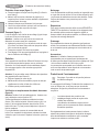
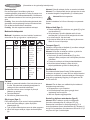
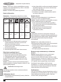
Cutting capacity
The wide vise opening and high pivot point provide cutting
capacity for many large pieces. Use the cutting
capacity chart to determine total maximum size of cuts that
can be made with a new wheel.
Caution: Certain large, circular or irregularly shaped objects
may require additional holding means if they cannot be held
securely in vise.

8
ENGLISH
(Original instructions)
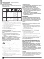
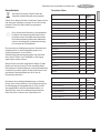
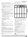
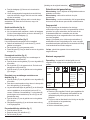
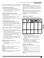
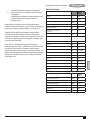
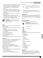
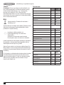
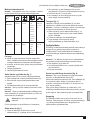
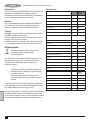
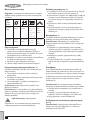
Maximum cutting capacity
Note: Capacity shown on chart assumes no wheel wear and
optimum fence position.
Workpiece
shape
90
O
cutting
angle
A = 4-7/8"
(125mm)
A = 4-1/2"
(115mm)
4-1/2" x 5-1/8"
(115mm x 130mm)
4" x 7-5/8"
(115mm x 130mm)
3" x 7-3/8"
(115mm x 130mm)
A = 4-1/2" x 5-3/8"
(115mm x 137mm)
45
O
Cutting
Angle
A= 4-1/2"
(115mm)
A = 3-13/16"
(98mm)
4-1/2" x 3-13/16"
4-1/8" x 3-3/4"
(105mm x 95mm)
A = 3-13/16"
3-3/4"
(95mm)
Prior to operation:
u Install the appropriate cutting disc. Do not use excessively
worn discs. The maximum rotation speed of the tool must
not exceed that of the cutting disc.
u Make sure the disc rotates in the direction of the arrows
on the accessory and the tool.
u Secure the workpiece.
u Always set the spark deector correctly.
Switching on and off (g. 1)
The on/off trigger switch (N) is mounted in the operating
handle.
u To run the tool, press the on/off trigger switch (N).
u Keep the on/off switch depressed while performing the
operation.
u To stop the tool, release the trigger switch (N).
Warning: Do not switch the tool on or off when under load.
Warning: To prevent unauthorized use of tool, install a
standard padlock (not included) into the padlock hole (O)
located in the trigger switch.
&
Warning! Do not cut magnesium.
Consult your dealer for further information on the
appropriate accessories.
Performing a cut (g. 1)
u Place the material to be cut against the fence (E) and
secure using the vise (F).
u Switch on the tool and pull down the handle to cut the
workpiece. Allow the motor to reach full speed before
cutting.
u Allow the disc to cut freely. Do not force.
u After completing the cut, switch off the tool and return the
arm to its upper rest position.
Transporting (g. 1)
The tool is equipped with a lock chain (A) which locks the
tool in closed-down position for carrying.
Warning: Ensure that the tool is switched off and
disconnected from the mains supply before transporting.
u Lower the guard (K) onto the cutting table base (D) and
secure the tool in this position by securing the chain on
the hook in the handle.
u Transport the tool using the carrying handles.
u To release the tool, depress the operating handle slightly
and pull off the lock chain (A).
Maintenance
Your Stanley Fat Max corded/cordless appliance/tool has
been designed to operate over a long period of time with a
minimum of maintenance. Continuous satisfactory operation
depends upon proper appliance/tool care and regular
cleaning.
Warning! Before performing any maintenance on corded/
cordless appliance/tool:
u Switch off and remove the battery from the appliance.
u Keep the ventilation slots clear and regularly clean the
housing with a soft cloth.
u Do not use abrasive cleaners.
Mains plug replacement (U.K. & Ireland only)
If a new mains plug needs to be tted:
u Safely dispose of the old plug.
u Connect the brown lead to the live terminal in the new
plug.
u Connect the blue lead to the neutral terminal.
Warning! No connection is to be made to the earth terminal.
Follow the tting instructions supplied with good quality
plugs. Recommended fuse: 13 A.
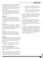
Motor brush inspection and replacement (g. 9)
Warning! Turn off and unplug the tool. Be sure the trigger
switch is in the OFF position.
Brushes should be regularly inspected for wear. To inspect
brushes, remove brush cap (W). Brushes (V) should slide
freely in brush box. If brushes are worn down to .3" (8mm) as
shown in Figure 9 they should be replaced.
To reinstall, push new brush back into brush box. If replacing
existing brush, maintain same orientation as when removed.
Replace the brush cap (do not overtighten).
Cleaning
Blowing dust and grit out of the main housing by means of an
air hose is recommended and may be done as often as dirt is
seen collecting in and around the air vents. Always wear
proper eye and respiratory protection.

9
ENGLISH
(Original instructions)
Repairs
To assure product SAFETY and RELIABILITY, repairs,
maintenance and adjustment should be performed by
authorized service centers or other qualied service
organizations, always using identical replacement parts.
Lubrication
Closed-type, grease-sealed ball bearings are used throughout.
These bearings have sufcient lubrication packed in them at
the factory to last the life of the chop saw.
Accessories
Caution! The use of any other accessory not recommended
for use with this tool could be hazardous.
Use only high-strength Type 1 organic bonded wheels rated
4300 rpm or higher that comply with EN12413.
Recommended accessories for use with your tool are
available at extra cost from your local dealer or authorized
service center.
Protecting the environment
Z
Separate collection. This product must not be
disposed of with normal household waste.
Should you nd one day that your Stanley Fat Max product
needs replacement, or if it is of no further use to you, do not
dispose of it with household waste. Make this product
available for separate collection.
z
Separate collection of used products and
packaging allows materials to be recycled and
used again.
Re-use of recycled materials helps prevent
environmental pollution and reduces the demand
for raw materials.
Local regulations may provide for separate collection of
electrical products from the household, at municipal waste
sites or by the retailer when you purchase a new product.
Stanley Europe provides a facility for the collection and
recycling of Stanley Fat Max products once they have reached
the end of their working life. To take advantage of this service
please return your product to any authorised repair agent who
will collect them on our behalf.
You can check the location of your nearest authorised repair
agent by contacting your local Stanley Europe ofce at the
address indicated in this manual. Alternatively, a list of
authorised Stanley Europe repair agents and full details of our
after-sales service and contacts are available on the Internet
at: www.2helpU.com
Technical data
FME700
(Type1)
Voltage V
AC
230
Power Input
W 2,300
No-Load Speed
min
-1
3,800
Max. Peripheral Speed Cutting Disc
m/s 80
Max. Disc Diameter
mm 355
Disc Bore
mm 25.4
Max Disc Thickness
mm
3
Type Of Cutting Disc
Straight, non recessed
Cross Cutting Capacity at 90
o
Circular
mm 125
Square
mm 115
Rectangular
mm 115 x 130
Angular
mm 137 x 137
Cross Cutting Capacity at 45
o
Circular
mm 115
Square
mm 98 x 98
Rectangular
mm 105 x 95
Angular
mm 95 x 95
Weight
kg 18
FME700
(Type1)
L
pA
(Sound Pressure) dB(A)
92.5
Uncertainty (K)
dB(A) 3
L
WA
(Sound Power) dB(A)
105.5
Uncertainty (K)
dB(A) 3
Vibration a
h
m/s
2
6.5
Uncertainty (K)
m/s
2
1.5

10
ENGLISH
(Original instructions)
EC declaration of conformity
MACHINERY DIRECTIVE
%
FME700
Stanley Europe declares that these products described under
"technical data" are in compliance with:
2006/42/EC, EN61029-1, EN61029-2-10
These products also comply with Directive 2004/108/EC and
2011/65/EU. For more information, please contact Stanley
Europe at the following address or refer to the back of the
manual.
The undersigned is responsible for compilation of the technical
le and makes this declaration on behalf of Stanley Europe.
_
Kevin Hewitt
Vice-President Global Engineering
Stanley Europe, Egide Walschaertsstraat14-18,
2800 Mechelen, Belgium
29/01/2013
Guarantee
StanleyEurope is condent of the quality of its products and
offers an outstanding guarantee for professional users of the
product. This guarantee statement is in addition to and in no
way prejudices your contractual rights as a private non-
professional user. The guarantee is valid within the territories
of the Member States of the European Union and the
European Free Trade Area.
ONE-YEAR FULL WARRANTY
If your Stanley Fat Max product becomes defective due to
faulty materials or workmanship within 12 months from the
date of purchase, Stanley Europe guarantees to replace all
defective parts free of charge or – at our discretion – replace
the unit free of charge provided that:
u The product has not been misused and has been used in
accordance with the instruction manual.
u The product has been subject to fair wear and tear;
u Repairs have not been attempted by unauthorised
persons;
u Proof of purchase is produced.
u The Stanley Fat Max product is returned complete with all
original components
If you wish to make a claim, contact your seller or check the
location of your nearest authorised Stanley Fat Max repair
agent in the Stanley Fat Max catalogue or contact your local
Stanley ofce at the address indicated in this manual. A list of
authorised Stanley Fat Max repair agents and full details of
our after sales service is available on the internet at:www.
stanley.eu/3
Page is loading ...
Page is loading ...
Page is loading ...
Page is loading ...
Page is loading ...
Page is loading ...
Page is loading ...
Page is loading ...
Page is loading ...
Page is loading ...
Page is loading ...
Page is loading ...
Page is loading ...
Page is loading ...
Page is loading ...
Page is loading ...
Page is loading ...
Page is loading ...
Page is loading ...
Page is loading ...
Page is loading ...
Page is loading ...
Page is loading ...
Page is loading ...
Page is loading ...
Page is loading ...
Page is loading ...
Page is loading ...
Page is loading ...
Page is loading ...
Page is loading ...
Page is loading ...
Page is loading ...
Page is loading ...
Page is loading ...
Page is loading ...
Page is loading ...
Page is loading ...
Page is loading ...
Page is loading ...
Page is loading ...
Page is loading ...
Page is loading ...
Page is loading ...
Page is loading ...
Page is loading ...
Page is loading ...
Page is loading ...
Page is loading ...
Page is loading ...
Page is loading ...
Page is loading ...
Page is loading ...
Page is loading ...
Page is loading ...
Page is loading ...
Page is loading ...
Page is loading ...
Page is loading ...
Page is loading ...
Page is loading ...
Page is loading ...
Page is loading ...
Page is loading ...
Page is loading ...
Page is loading ...
Page is loading ...
Page is loading ...
Page is loading ...
Page is loading ...
Page is loading ...
Page is loading ...
Page is loading ...
Page is loading ...
Page is loading ...
Page is loading ...
Page is loading ...
Page is loading ...
Page is loading ...
Page is loading ...
Page is loading ...
Page is loading ...
Page is loading ...
Page is loading ...
Page is loading ...

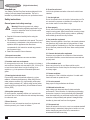
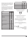
TYP
19 - 03 - 12
E16613
1
FME700
www.2helpU.com
800
88
64
87
86
79
84
85
85
91
92
79
81
83
59
60
61
62
63
67
66
68
70
71
74
75 80
78
79
77
76
73
72
1
2
3
5
6
3
6
7
8
9
10
11
8
17
18
19
21
20
22
48
54
47
42
46
57
55
47
42
46
93
45
44
39
41
1
40
39
38
1
40
39
26
27
25
23
24
8
28
31
32
33
34
35
36
37
23
24
46
69
30
29
25g
94
34
35
36
Page is loading ...
Page is loading ...
Page is loading ...

90595663 REV-0 01/2013
België/Belgique Stanley Fat Max De. Tel. +32 70 220 065
E. Walschaertstraat 14-16 Fr. Tel. +32 70 220 066
2800 Mechelen Fax +32 15 473 799
Belgium www.stanleytools.eu
Danmark Stanley Fat Max Tel. 70 20 15 10
Farveland 1B Fax 70 22 49 10
2600 Glostrup www.stanleyworks.dk
Deutschland Stanley Fat Max Tel. 06126 21-1
Richard Klinger Str. 11, D - 65510 Idstein Fax 06126 21-2770
Ελλάδα Stanley Fat Max. Τηλ. +30 210 8981-616
Στράβωνος 7 & Λεωφ. Βουλιαγμένης 159 Φαξ +30 210 8983-285
Гλυφάδα 166 74 - Αθήνα www.stanleyworks.gr
España Stanley Fat Max. Tel. 934 797 400
Parc de Negocis “Mas Blau” Fax 934 797 419
08820 El Prat de Llobregat (Barcelona) www.stanleyworks.es
France Stanley Fat Max Tel. 04 72 20 39 20
5 allée des Hêtres Fax 04 72 20 39 00
B.P. 30084 www.stanleyoutillage.fr
69579 Limonest Cédex
Helvetia Stanley Fat Max Tel. 01 730 67 47
In der Luberzen 40 Fax 01 730 70 67
8902 Urdorf www.stanleyworks.de
Italia Stanley Fat Max Tel. 039-9590200
Energypark–Building 03 sud, Via Monza 7/A Fax 039-9590313
20871 Vimercate (MB) www.stanley.it
Nederland Stanley Fat Max Tel. +31 164 283 065
Joulehof 12, Fax +31 164 283 200
Norge Stanley Fat Max Tlf. 45 25 13 00
Postboks 4613, Nydalen Fax 45 25 08 00
0405 Oslo
Österreich Stanley Fat Max Tel. 01 66116-0
Oberlaaerstraße 248, Fax 01 66116-614
A-1230 Wien www.stanleyworks.de
Portugal Stanley Fat Max Tel. 214667500
Centro de Escritórios de Sintra Avenida Almirante Fax 214667575
2710-418 Lisboa
Suomi Stanley Fat Max Puh. 010 400 430
Tekniikantie 12, 02150 Espoo Faksi 0800 411 340
www.stanleyworks.
Sverige Stanley Fat Max Tel. 031-68 61 00
Box 94, 431 22 Mölndal Fax 031-68 60 08
Türkiye Stanley Fat Max Puh. 0212 533 52 55
KALE Hırdavat ve Makina A.Ş. Faks 0212 533 10 05
Defterdar Mah. Savaklar Cad. No:15 www.stanleyworks.
Edirnekapı / Eyüp / İSTANBUL 34050
United Kingdom Stanley Fat Max Tel. +44 (0)1753 511234
210 Bath Road Fax +44 (0)1753 551155
Slough, Berkshire SL1 3YD www.stanleytools.co.uk
Middle East & Africa Stanley Fat Max Tel. +971 4 8127400
P.O.Box - 17164 Fax +971 4 8127036
Jebel Ali (South Zone), Dubai, www.stanleyworks.ae
UAE
-
 1
1
-
 2
2
-
 3
3
-
 4
4
-
 5
5
-
 6
6
-
 7
7
-
 8
8
-
 9
9
-
 10
10
-
 11
11
-
 12
12
-
 13
13
-
 14
14
-
 15
15
-
 16
16
-
 17
17
-
 18
18
-
 19
19
-
 20
20
-
 21
21
-
 22
22
-
 23
23
-
 24
24
-
 25
25
-
 26
26
-
 27
27
-
 28
28
-
 29
29
-
 30
30
-
 31
31
-
 32
32
-
 33
33
-
 34
34
-
 35
35
-
 36
36
-
 37
37
-
 38
38
-
 39
39
-
 40
40
-
 41
41
-
 42
42
-
 43
43
-
 44
44
-
 45
45
-
 46
46
-
 47
47
-
 48
48
-
 49
49
-
 50
50
-
 51
51
-
 52
52
-
 53
53
-
 54
54
-
 55
55
-
 56
56
-
 57
57
-
 58
58
-
 59
59
-
 60
60
-
 61
61
-
 62
62
-
 63
63
-
 64
64
-
 65
65
-
 66
66
-
 67
67
-
 68
68
-
 69
69
-
 70
70
-
 71
71
-
 72
72
-
 73
73
-
 74
74
-
 75
75
-
 76
76
-
 77
77
-
 78
78
-
 79
79
-
 80
80
-
 81
81
-
 82
82
-
 83
83
-
 84
84
-
 85
85
-
 86
86
-
 87
87
-
 88
88
-
 89
89
-
 90
90
-
 91
91
-
 92
92
-
 93
93
-
 94
94
-
 95
95
-
 96
96
-
 97
97
-
 98
98
-
 99
99
-
 100
100


Ask a question and I''ll find the answer in the document
Finding information in a document is now easier with AI
in other languages
- italiano: Stanley FME700 Manuale del proprietario
- français: Stanley FME700 Le manuel du propriétaire
- español: Stanley FME700 El manual del propietario
- Deutsch: Stanley FME700 Bedienungsanleitung
- Nederlands: Stanley FME700 de handleiding
- português: Stanley FME700 Manual do proprietário
- dansk: Stanley FME700 Brugervejledning
- svenska: Stanley FME700 Bruksanvisning
- suomi: Stanley FME700 Omistajan opas