
5
ENGLISH
power tool’s operation. If damaged, have the power
tool repaired before use. Many accidents are caused by
poorly maintained powertools.
f ) Keep cutting tools sharp and clean. Properly
maintained cutting tools with sharp cutting edges are less
likely to bind and are easier tocontrol.
g ) Use the power tool, accessories and tool bits, etc.
in accordance with these instructions, taking into
account the working conditions and the work to be
performed. Use of the power tool for operations different
from those intended could result in a hazardoussituation.
h ) Keep handles and grasping surfaces dry, clean and
free from oil and grease. Slippery handles and grasping
surfaces do not allow for safe handling and control of the
tool in unexpectedsituations.
5) Service
a ) Have your power tool serviced by a qualified repair
person using only identical replacement parts. This
will ensure that the safety of the power tool ismaintained.
Safety Instructions for Cut-off Machines
1) Cut-off Machine Safety Warnings
a ) Position yourself and bystanders away from the
plane of the rotating wheel. The guard helps to protect
the operator from broken wheel fragments and accidental
contact withwheel.
b ) Use only bonded reinforced cut-off wheels for your
power tool. Just because an accessory can be attached to
your power tool, it does not assure safe operation.
c ) The rated speed of the accessory must be at least
equal to the maximum speed marked on the power
tool. Accessories running faster than their rated speed can
break and fly apart.
d ) Wheels must be used only for recommended
applications. For example: do not grind with the side
of a cut-off wheel. Abrasive cut-off wheels are intended
for peripheral grinding, side forces applied to these wheels
may cause them toshatter.
e ) Always use undamaged wheel flanges that are of
correct diameter for your selected wheel. Proper
wheel flanges support the wheel thus reducing the
possibility of wheelbreakage.
f ) The outside diameter and the thickness of your
accessory must be within the capacity rating of
your power tool. Incorrectly sized accessories cannot be
adequately guarded orcontrolled.
g ) The arbour size of wheels and flanges must properly
fit the spindle of the power tool. Wheels and flanges
with arbour holes that do not match the mounting
hardware of the power tool will run out of balance, vibrate
excessively and may cause loss ofcontrol.
h ) Do not use damaged wheels. Before each use,
inspect the wheels for chips and cracks. If the power
tool or wheel is dropped, inspect for damage or
install an undamaged wheel. After inspecting
and installing the wheel, position yourself and
bystanders away from the plane of the rotating
wheel and run the power tool at maximum no load
speed for one minute. Damaged wheels will normally
break apart during this testtime.
i ) Wear personal protective equipment. Depending
on application, use face shield, safety goggles or
safety glasses. As appropriate, wear a dust mask,
hearing protectors, gloves and shop apron capable
of stopping small abrasive or workpiece fragments.
The eye protection must be capable of stopping flying
debris generated by various operations. The dust mask or
respirator must be capable of filtrating particles generated
by your operation. Prolonged exposure to high intensity
noise may cause hearingloss.
j ) Keep bystanders a safe distance away from work
area. Anyone entering the work area must wear
personal protective equipment. Fragments of
workpiece or of a broken wheel may fly away and cause
injury beyond immediate area ofoperation.
k ) Position the cord clear of the spinning accessory. If
you lose control, the cord may be cut or snagged and your
hand or arm may be pulled into the spinningwheel.
l ) Regularly clean the power tool’s air vents. The
motor’s fan can draw the dust inside the housing and
excessive accumulation of powdered metal may cause
electricalhazards.
m ) Do not operate the power tool near flammable
materials. Do not operate the power tool while
placed on a combustible surface such as wood.
Sparks could ignite thesematerials.
n ) Do not use accessories that require liquid coolants.
Using water or other liquid coolants may result in
electrocution orshock.
Kickback and Related warnings
Kickback is a sudden reaction to a pinched or snagged rotating
wheel. Pinching or snagging causes rapid stalling of the rotating
wheel which in turn causes the uncontrolled cutting unit to be
forced upwards toward theoperator.
For example, if an abrasive wheel is snagged or pinched by the
workpiece, the edge of the wheel that is entering into the pinch
point can dig into the surface of the material causing the wheel
to climb out or kick out. Abrasive wheels may also break under
theseconditions.
Kickback is the result of power tool misuse and/or incorrect
operating procedures or conditions and can be avoided by taking
proper precautions as givenbelow.
a ) Maintain a firm grip on the power tool and position
your body and arm to allow you to resist kickback
forces. The operator can control upward kickback forces,
if proper precautions aretaken.
b ) Do not position your body in line with the rotating
wheel. If kickback occurs, it will propel the cutting unit
upwards toward theoperator.
c ) Do not attach a saw chain, woodcarving blade,
segmented diamond wheel with a peripheral gap


 1
1
 2
2
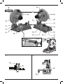 3
3
 4
4
 5
5
 6
6
 7
7
 8
8
 9
9
 10
10
 11
11
 12
12


