AEG DU 3150 User manual

Category
Cooker hoods
Type
User manual
61
Contents
Safety warnings .............................................................................. 62
For the user ...................................................................................... 62
For the installer ................................................................................. 63
Description of the Appliance ......................................................... 65
Extraction mode................................................................................ 65
Recirculation mode ........................................................................... 65
Control Panel ............................................................................. 66-67
Control Panel - DU 4561 ............................................................ 68-69
Maintenance and Care................................................................... 70
Cleaning the hood ............................................................................. 70
Paper grease filter ............................................................................. 71
Metal grease filter ............................................................................. 72
Charcoal filter .................................................................................... 73
Changing the light bulb ...................................................................... 74
What to do if ................................................................................... 75
Special accessories........................................................................ 75
Technical assistance service ......................................................... 76
Technical Specifications ................................................................ 77
Mounting accessories included ......................................................... 78
Electrical connection ..................................................................... 78
Wall unit mounting ............................................................................ 79
Wall mounting ................................................................................... 80
62
Safety warnings
For the user
The cooker hood is designed to extract unpleasant odours from the
kitchen, it will not extract steam.
Always cover lighted elements, to prevent excess heat from
damaging the appliance. In the case of oil, gas and coal fired
cookers it is essential to avoid open flames.
Also, when frying, keep the deep frying pan on the cooker top/cooker
under careful control.
The hot oil in the frying pan might ignite due to overheating.
The risk of self-ignition increases when the oil being used is dirty.
It is extremely important to note that overheating can cause a fire.
Never carry out any flambé cooking under the hood.
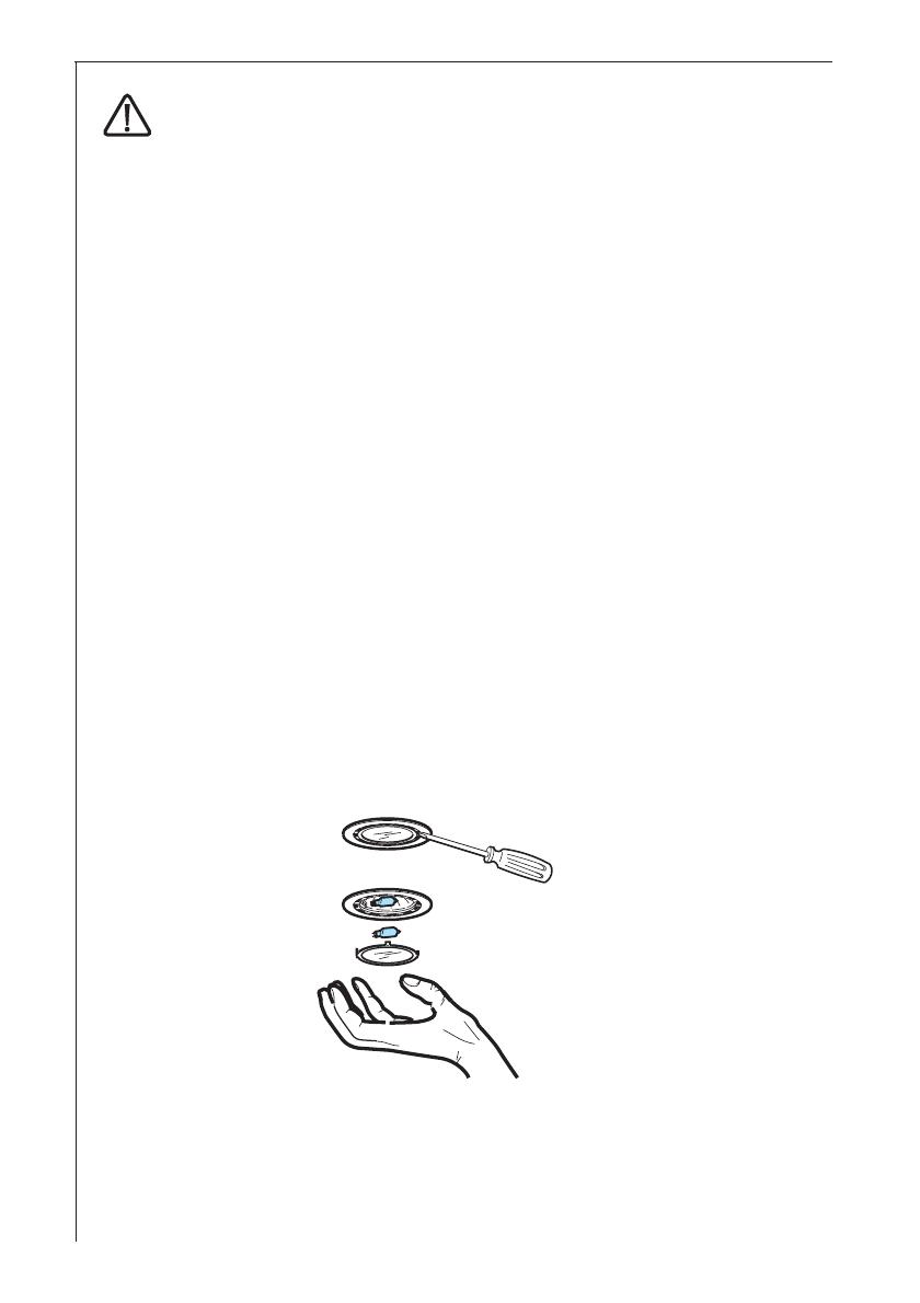
Always disconnect the unit from the power supply before
carrying out any work on the hood, including replacing the
light bulb (take the cartridge fuse out of the fuse holder or switch off
the automatic circuit breaker).
It is very important to clean the hood and replace the filter at
the recommended intervals. Failure to do so could cause
grease deposits to build up, resulting in a fire hazard.
The appliance is not intended for use by young children or infirm
persons without supervision.
Older children must be supervised if using the appliance.
Young children should be supervised to ensure that they do not play
with the appliance.
WARNING - Ensure that the appliance is switched off before
replacing the lamp to avoid the possibility of electric shock.
This appliance is marked according to the European directive 2002/96/
EC on Waste Electrical and Electronic Equipment (WEEE).
By ensuring this product is disposed of correctly, you will help prevent
potential negative consequences for the environment and human health,
which could otherwise be caused by inappropriate waste handling of
this product.
The symbol on the product, or on the documents accompanying
the product, indicates that this appliance may not be treated as
household waste. Instead it shall be handed over to the applicable
collection point for the recycling of electrical and electronic equipment.
Disposal must be carried out in accordance with local environmental
regulations for waste disposal.
For more detailed information about treatment, recovery and recycling
of this product, please contact your local city office, your household
waste disposal service or the shop where you purchased the product.
63
For the installer
When used as an extractor unit, the hood must be fitted with a
125mm diameter hose.
DU 3150/3160/4561/4361/4161: Should there already be a pipe of
diameter 100 that ducts to the outside through the walls, it is
possible to use the 125-100 mm reduction flange provided.
In this case the hood will be slightly noisier.
When installing the hood, make sure you observe the follow-
ing minimum distance from the top edge of the cooking hob/
ring surfaces:
electric cookers 500 mm
gas cookers 700 mm
If the instructions for installation for the gas hob specify a greater
distance, this must be adhered to.
The national Standard on fuel-burning systems specifies a maximum
depression of 0.04 mbar in such rooms.
The air outlet must not be connected to chimney flues or combustion
gas ducts. The air outlet must under no circumstances be connected
to ventilation ducts for rooms in which fuel-burning appliances are
installed.
The air outlet installation must comply with the regulations laid down
by the relevant local authorities.
When the unit is used in extraction mode, a sufficiently large
ventilation hole must be provided, with dimensions that are approxi-
mately the same as the outlet hole.
National and regional building regulations impose a number of
restrictions on using hoods and fuel-burning appliances connected to
a chimney, such as coal or oil room-heaters and gas fires, in the
same room.
Hoods can only be used safely with appliances connected to a
chimney if the room and/or flat (air/environment combination) is
ventilated from outside using a suitable ventilation hole approximately
500-600 cm
2
large to avoid the possibility of a depression being
created during operation of the hood.
If you have any doubts, contact the relevant controlling authority or
building inspectors office.
Since the rule for rooms with fuel burning appliances is outlet hole of
the same size as the ventilation hole, a hole of 500-600 cm
2
, which
is to say a larger hole, could reduce the performance of the extractor
hood.
If the hood is used in its recirculation mode, it will operate simply and
safely in the above conditions without the need for any of the
64
aforementioned measures.
When the hood is used in its extraction mode, the following rules
must be followed to obtain optimal operation:
- short and straight outlet hose
- keep bends in outlet hose to a minimum
- never install the hoses with an acute angle, they must always
follow a gentle curve.
- keep the hose as large as possible (preferably the same diameter
as the outlet hole).
- the length should be no more than:
3 metres with one 90° bend
2 metres with two 90° bends
Bends of more than 90° will reduce the efficiency of the hood and
reduce the airflow.
Failure to observe these basic instructions will drastically reduce the
performance and increase the noise levels of the extractor hood.
65
90°
Description of the Appliance
The cooker hood is designed to extract unpleasant odours from
the kitchen, it will not extract steam.
The hood is supplied as an extractor unit and can also be used with a
recirculation mode by fitting a charcoal filter.
In some models the charcoal filter is supplied. The hood, therefore,
can be used immediately in the recirculation mode. We advise
removing the charcoal filter to use the hood in the extraction mode.
Extraction mode
In this mode fumes are extracted to the
outside via a hose connected to the
coupling ring C. Fig. 1.
In order to obtain the best performance the
hose should have a diameter equal to the
outlet hole.
Should there already be a pipe of diameter
100 that ducts to the outside through the
walls, it is possible to use the 125-100 mm
reduction flange provided.
In this case the hood will be slightly noisier.
Recirculation mode
The air is filtered through a charcoal filter and returned to the
kitchen.
Move the lever to position F - Fig. 2.
You will need an original charcoal filter for the recirculation mode.
(See Special Accessories).
Fig. 2
1
2
Ø 125 mm
Ø 100 mm
C
Bild 1
Lever
charcoal filter
66
Control Panel - DU 3150/3160/4161
Best results are obtained by using a low speed for normal conditions
and a high speed when odours are more concentrated.
Turn the hood on a few minutes before you start cooking.
The hood should be left on after cooking for about 15 minutes or until
all the odours have disappeared.
The control switches are located on the hoods front panel:
the light switch switches the hood lamp on and off
the motor switch switches the motor on and off, enabling you to
select one of the three different speeds.
Light switch
Motor switch
DU 3150
DU 3160
DU 4161
Light switch
Motor switch
67
Control Panel - DU 3360/4360/4361
Best results are obtained by using a low speed for normal conditions
and a high speed when odours are more concentrated.
Turn the hood on a few minutes before you start cooking.
The hood should be left on after cooking for about 15 minutes or until
all the odours have disappeared.
The control switches are located on the hoods front panel:
the light switch switches the hood lamp on and off
the motor switch switches the motor off
Speed 1: Speed 1 push-button
Speed 2: Speed 2 push-button
Speed 3: Speed 3 push-button
Light switch
Motor switch
Speed 1
Speed 2
Speed 3
68
Control Panel - DU 4561
Best results are obtained by using a low speed for normal conditions
and a high speed when odours are more concentrated.
Turn the hood on a few minutes before you start cooking.
The hood should be left on after cooking for about 15 minutes or until
all the odours have disappeared.
The control switches are located on the hoods front panel:
A - OFF ON push button
Press once or more to obtain the function desired:
ON: the hood switches on to the last speed selected.
OFF: all the functions are switched off except the illumination.
B - Speed selection push button (extraction power).
Press this push button once or more to select the most suitable
extraction speed (power) (1-2-3).
C - The display shows the extraction power selected, signalling the
saturation of the filters (F).
D - Intensive speed on/off. The Intensive speed runs for 5 minutes:
If the hood is on when the Intensive speed is activated, the hood
reverts to previous speed after 5 minutes.
If the hood is off when the Intensive speed is activated, the hood
will be turned off after 5 minutes.
To interrupt the Intensive speed, press button A or B.
H - Light ON/OFF
Should the hood or the controls fail to operate: disconnect the power
supply for at least 5 seconds, then turn the hood back on again.
i
AB
C
DE
69
Grease and charcoal filter maintenance
indicator - DU 4561
This hood is fitted with a device that indicates when it is necessary to
clean the grease filter or the charcoal filter (if the hood is used in the
recirculation version with a charcoal filter).
On delivery, the hood is not supplied with a charcoal filter, so the
saturation indicator will be disabled.
If the hood is to be used with a charcoal filter, the saturation
indicator light must be enabled as follows:
Set the hood in OFF.
Pressing keys B and D simultaneously for three seconds, LED F lights
up and begins to flash the 1
st
speed led. After 1 second the 2
nd
speed
led also flashes and the system emits a sound signal (-Beep-) to
indicate setting taking place.
To remove the charcoal filter signal press push buttons B and D
simultaneously for 3 seconds. LED F lights up and begins to flash the
1
st
speed led (grease filter) and the 2
nd
speed led. After 1 second, only
the 1
st
speed led continues to flash. The system emits a sound signal
(-Beep-) to indicate setting taking place.
Grease filter LED
The 1
st
speed led (+ led F) flashes, when it is time to clean the grease
filter.
Always comply with the maintenance instructions for the grease filter.
Charcoal filter LED
The 2
nd
speed led (+ led F) flashes, when the charcoal filter needs to
be cleaned or replaced.
Resetting the saturation indicator
After cleaning or replacing the filters, press button 1 for 3 seconds until
the 1
st
speed led or the second speed led stops flashing.
The F LED also turns off..
70
Maintenance and Care
The hood must always be disconnected from the electricity
supply before beginning any maintenance work.
Cleaning the hood
Clean the outside of the hood using a damp cloth and a solution of
water and mild washing up liquid.
Never use corrosive, abrasive or flammable cleaning products or
products containing bleach. .
Never insert pointed objects in the motors protective grid.
Only ever clean the switch panel and filter grill using a damp cloth
and mild washing up liquid.
It is extremely important to clean the unit and change the filters at the
recommended intervals. Failure to do so will cause grease deposits
to build up that could constitute a fire hazard.
71
Paper grease filter- DU 3150 - DU 3160 - DU 3360
The purpose of the grease filters is to absorb grease particles which
form during cooking and it must always be used, either in the
external evacuation or internal recycling function.
The paper grease filter is very thin (approx. 1 mm) and positioned on
the inside of its related support grille.
The filter should be changed once a month.
The grille should be cleaned with luke warm water and non-abrasive
detergent when you change the filter.
The grease filter can be ordered from your local Service Force
Centre.
Opening the grille
Open the latch and swing the grille downwards.
To remove the grille, pull it forwards from the right and release it.
Fig. 3.
Removing the filter
Open the grille and remove the stops to take out the filter. Fig. 3.
Fig. 3
1
2
3
Paper grease filter
Stops
Latch
Grille
Latch
72
Metal grease filter - DU 4360/4161/4361/4561
The purpose of the grease filters is to absorb grease particles which
form during cooking and it must always be used, either in the
external extraction or internal re-circulation function.
Attention: the metal grease filters must be removed and washed,
either by hand or in the dishwasher, every four weeks.
Removing the metal grease filter
First pull the latches backwards (a), then extract the grille outwards
(b). Fig. 4.
Hand washing
Soak grease filters for about one hour in hot water with a grease-
loosening cleaner, then rinse off thoroughly with hot water. Repeat the
process if necessary. Refit the grease filters when they are dry.
Dishwasher
Place grease filters in the dishwasher. Select most powerful washing
programme and highest temperature, at least 65°C. Repeat the
process. Refit the grease filters when they are dry.
When washing the metal grease filter in the dishwasher a slight
discolouration of the filter can occur, this does not have any impact
on its performance.
Clean the inner housing using a hand hot solution only(never use
caustic detergents, abrasive powders or brushes).
a
b
b
a
a
a
Latch
Fig. 4
73
90°
Fig. 5
charcoal filter
knobs
cover
Charcoal filter
The charcoal filter should only be used if you want to use the hood in
recirculation mode.
To do this you will need an original charcoal filter (available from your
local Service Force Centre).
The charcoal filter cannot be washed nor regenerated.
The charcoal filter should be replaced every 4 months under normal
use.
Replacement filters are available from your local Service Force
Centre.
Fitting
Remove the cover by rotating the knobs to 90°, put the charcoal
filter inside and fix it by rotating the knob to 90° then close the
cover. Fig. 5.
To remove proceed in the reverse order.
Always specify the hood model code number and serial number when
ordering replacement filters. This information is shown on the rating
plate located on the inside of the unit.
The charcoal filter can be ordered from your local Service Force
Centre.
74
Warning
Failure to observe the instructions on cleaning the unit and changing
the filters will cause a fire hazard. You are therefore strongly
recommended to follow these instructions.
The manufacturer declines all responsibility for any damage to the
motor or any fire damage linked to inappropriate maintenance or
failure to observe the above safety recommendations.
Changing the light bulb
Disconnect the cooker hood from the mains supply.
Remove the grid.
Replace the old bulb with a new one of the same type.
Refit the grid.
If the light does not come on, make sure the bulb has been inserted
in correctly before contacting your local Service Force Centre.
Changing the light bulb - DU 4561
Disconnect the cooker hood from the mains supply.
Remove the lamp cover carefully, use a screw driver as a lever. Fig. 6.
Replace the old bulb with a new one of the same type.
Refit the lamp cover.
If the light does not come on, make sure the bulb has been inserted
in correctly before contacting your local Service Force Centre.
Fig. 6
75
What to do if
If your appliance fails to work properly please carry out the following
checks.
Symptom Solution
The cooker hood Check that: The hood is connected to
will not start... the electricity supply.
Check that a fan speed has been
selected
The cooker hood Check that: The fan speed is set
is not working high enough for the task.
The grease filters are clean.
The kitchen is adequately vented to
allow the entry of fresh air.
If set up for recirculation, check that
the charcoal filter is still effective.
If set up for extraction, check that the
ducting and outlets are not blocked.
The cooker hood has The safety cut-out device has been
switched off tripped.
during operation... Turn off the hob and then wait for
the device to reset.
If the hood has been installed below
the heights indicated in the
installation instructions the motor
will cut-out frequently which will
damage the hood.
If after all these checks, the problem persists, contact your local
Service Force Centre, quoting the model and serial number.
Please note that it will be necessary to provide proof of purchase for
any in-guarantee service calls.
In-guarantee customers should ensure that the above checks have
been made as the engineer will make a charge if the fault is not a
mechanical or electrical breakdown.
Special accessories
Charcoal filter TYPE 10
76
Technical assistance service (not for UK)
You are welcome to telephone our technical assistance service (see list of technical
assistance centres) whenever you need information or in the unlikely event of a fault.
For service in Australia call 1300 650 020.
When calling, please be ready to specify:
1. The model code number
2. The serial number (E-Nr.)
3. The manufacturing number (F-Nr.)
This information is shown on the registration plate inside the unit behind the
grease filter.
We reserve the right to change specifications and colours as a result of our policy of
continuing technological development.
Service and Spare Parts
In the event of your appliance requiring service, or if you wish to purchase spare parts,
contact your local Service Force Centre by telephoning: 08705 929 929
Your call will be automatically routed to the Service Centre covering your post code
area. For the address of your local Service Force Centre and further information about
Service Force, please visit the website at www.serviceforce.co.uk
Please ensure that you have read the section What to do if.... as the engineer will make
a charge if the fault is not a mechanical or electrical breakdown even the appliance is
under warranty. Please note that proof of purchase is required for in-guarantee
service calls.
Help us to help you
Please determine your type of enquiry before writing or telephoning.
When you contact us we need to know:
Your name Clear and concise details of the fault
Address and post code Name and model of the appliance*
Telephone number E number*
Serial number*
* This information can be found on the rating plate, which can be seen when the grease
filters are removed.
If you require Customer Service in the Republic of Ireland please contact us
at the address below:
AEG
Electrolux Group (Ire) Ltd
Long Mile Road
Dublin 12
Republic of Ireland
Tel: + 353 (0) 1 4090751
77
Technical Specifications
Models: DU 3150 DU 3160 DU 3360 DU 4361 DU 4561
DU 4360
DU 4161
Dim. (in cm):
Height 13,2 13,2 13,2 13,2 13,2
Width 49,9 59,9 59,9 59,9 59,9
Depth/(DU 4161) 51 51 51/(51,2) 51,2 51,2
Max. absorbed
power: (in W): 140 140 180 220 180
Motor (in W): 100 100 100 140 140
Lighting (in W): 40 40 2 x 40 2 x 40 2 x 20
Length of the
cables (in cm): 150 150 150 150 150
Electrical
connection (in V): 220-240 220-240 220-240 220-240 220-240
Fuse rating (for all models)*: 5A Time Delay Fuse
* Only for UK.
CUSTOMER CARE DEPARTMENT
For general enquiries concerning your AEG appliance or for further information on AEG
products, please contact our Customer Care Department by letter or telephone at the
address below or visit our website at www.aeg.co.uk
Customer Services Department
Major Appliances
AEGElectrolux
Addington Way
Luton
Bedfordshire
LU4 9QQ
08705 350 350 (*)
* calls to this number may be recorded for training purposes.
78
Mounting accessories included
3 screws 5 x 45 mm
3 wall plugs Ø 8 mm (brick fixing only)
4 screws 4,2 x 35 mm
1 screw 2,9 x 13 mm
1 flange Ø 125 mm
1 flange Ø 125/100 mm (DU 3150/3160/4161/4361/4561)
1 allen spanner (for TORX screws)
Electrical connection (not for UK)
Safety warnings for the electrician
Before connecting the appliance to the power supply, check that the
voltage indicated on the rating plate corresponds to the mains power
supply available. Appliances fitted with a plug can be connected to any
standard power socket within easy access.
Should it be necessary to provide a fixed connection, the hood must
only be installed by an electrician authorised by the local electricity
board. When installing, an omnipolar disconnector with a distance of at
least 3 mm between contacts must be provided.
Fixed connection of the appliance must only be carried out by an
authorised electrician.
Electrical connection for UK only
Safety warnings for the electrician
Connect the hood to the mains supply via a double pole switch
which has 3 mm minimum separation between the contacts.
The switch must be accessible at all times.
The following is valid in the United Kingdom only:
- the wire which is coloured blue must be connected to the terminal
which is marked with the letter N or coloured black, -
- the wire which is coloured brown must be connected to the terminal
which is marked with the letter L or coloured red.
79
Wall unit mounting - Fig. 7
Make the holes on the bottom of the cupboard (2), using
the drilling template (1).
Provide a hole also for the ducting pipe (4) ONLY if is decided to use
the hood in the extractor version (3).
From inside the cupboard, insert the 4 supplied screws (5) and tighten
them in the appropriate holes on the appliance.
Fig. 7
1
2
5
4
5
5
5
3
80
Fig. 8
Wall mounting - Fig. 8
Mark a centre line on the wall (1).
Fix the drilling template to the wall (2).
Make 3 Ø 8mm holes in the wall (3), 2 at upper points, 1 as desired
at lower points.
Insert the three Ø 8mm expansion plugs into the wall (4).
Insert 2 5x45 screws (5) but do not tighten them completely, hang the
hood (6).
Only DU 4161 - DU 4361 - DU 4561: Adjust the unit so that it is
positioned at a right angle to the wall by turning the two screws on
lower side (7).
Tighten the 2 upper screws (8).
From inside the hood, insert the third 5x45 screw into the lower hole
(9) and tighten (10).
2
3
4
4
4
5
5
3
1
6
6
9
8
1cm
5
!
10
8
7
7
1 / 1

AEG DU 3150 User manual

Category
Cooker hoods
Type
User manual

Ask a question and I''ll find the answer in the document

Finding information in a document is now easier with AI

Ask the document

in other languages