Page is loading ...

TH114-A/AF-120S/240S/240D
Non-programmable thermostat
Thermostat non programmable
Termostato no programable
400-114-029-A
Owner’s Guide
Guide du propriétaire
Guía para el usuario
400-114-029-A (Honeywell TH114-A_AF-120S_240S_240D) 5 x 3.125 EFS.book Page 1 Friday, August 27, 2010 4:10 PM

Need Help?
We are here to help. Call 1-800-831-2823.
Besoin d’aide?
Nous sommes là. Composez le 1 800 831-2823.
¿Asistencia?
Estamos aquí para ayudarlo. Llame al 1 800 831-2823.
400-114-029-A (Honeywell TH114-A_AF-120S_240S_240D) 5 x 3.125 EFS.book Page 2 Friday, August 27, 2010 4:10 PM

TH114-A/AF-120S/240S/240D
1
ENGLISH
Overview & operation
Before you start...........................................................................................................................................2
About your thermostat.................................................................................................................................3
Controls and display....................................................................................................................................4
Installation
Installing the thermostat..............................................................................................................................6
Wiring diagrams..........................................................................................................................................7
Connecting the floor temperature sensor / remote control system .............................................................8
Setting the configuration switches...............................................................................................................9
Appendix
Floor temperature limits.............................................................................................................................10
Unoccupied Mode.....................................................................................................................................11
Error messages.........................................................................................................................................12
Technical specifications.............................................................................................................................13
Warranty....................................................................................................................................................14
Table of contents
400-114-029-A (Honeywell TH114-A_AF-120S_240S_240D) 5 x 3.125 EFS.book Page 1 Friday, August 27, 2010 4:10 PM

Owner’s Guide
2
ENGLISH
Read the entire document
CAUTION:
• Installation must be carried out by a certified electrician and must comply with national and local
electrical codes.
• To prevent severe shock or electrocution, always cut the power at the service panel before working
with wiring.
• Use this thermostat for resistive loads only.
• Do NOT install the thermostat in an area where it can be exposed to water or rain.
• Avoid locations where there are air drafts (top of staircase, air outlet), dead air spots (behind a
door), direct sunlight or concealed chimney or stove pipes (except for floor heating systems).
• For a new installation, choose a location about 1.5 m (5 ft.) above the floor.
• Install the thermostat on an inside wall facing the heating system (except for floor heating systems).
• Install the thermostat onto an electrical box.
• Use special CO/ALR solderless connectors if you connect the thermostat to aluminum wires.
• Keep the thermostat's top and bottom air vents (openings) clean and unobstructed at all times.
Before you start
400-114-029-A (Honeywell TH114-A_AF-120S_240S_240D) 5 x 3.125 EFS.book Page 2 Friday, August 27, 2010 4:10 PM

TH114-A/AF-120S/240S/240D
3
ENGLISH
The TH114 non-programmable thermostat has three temperature control modes:
See page 9 on how to change the temperature control mode setting.
* Select models only; required for floor heating applications only.
About your thermostat
A mode: controls the ambient air temperature
F mode: controls the floor temperature using an external temperature sensor
AF mode: controls the ambient air temperature
maintains the floor temperature within desired limits using an external temperature
sensor
Supplied Parts
• One (1) thermostat
• Two (2) mounting screws
• Four (4) solderless connectors for copper wires
• One (1) floor sensor *
• One (1) flat-tip screwdriver *
400-114-029-A (Honeywell TH114-A_AF-120S_240S_240D) 5 x 3.125 EFS.book Page 3 Friday, August 27, 2010 4:10 PM

Owner’s Guide
4
ENGLISH
Controls and display
Backlight button (see page 5)
Temperature adjustment button
On/Off or On/Standby
switch (see page 5)
Heating indicator. The number
of flames indicates the heating
intensity. The image disappears
when heating stops.
Temperature (see page 5)
Unoccupied Mode indicator
(see page 11)
Appears when the set
temperature is displayed
400-114-029-A (Honeywell TH114-A_AF-120S_240S_240D) 5 x 3.125 EFS.book Page 4 Friday, August 27, 2010 4:10 PM

TH114-A/AF-120S/240S/240D
5
ENGLISH
Temperature Display and Setting
The thermostat usually displays the room temperature. To view the set (desired)
temperature, press either of the buttons once. The set temperature is displayed for 5
seconds.
To set a new temperature, press one of the buttons repeatedly until the desired
temperature is displayed. To scroll faster, press and hold the button.
Backlight
The display illuminates for 5 seconds when the backlight button is pressed.
When either of the buttons is pressed, the display illuminates for 10 seconds. The set-
point temperature appears for the first 5 seconds, then the current temperature is displayed.
On/Off or On/Standby Switch
You can set the thermostat to Off or Standby to cut power to the heating system when it is not
in use (e.g. in summer). The thermostat screen becomes blank but the settings are saved.
400-114-029-A (Honeywell TH114-A_AF-120S_240S_240D) 5 x 3.125 EFS.book Page 5 Friday, August 27, 2010 4:10 PM

Owner’s Guide
6
ENGLISH
Turn the heating system off at the main electrical panel.
Loosen the bottom screw and remove the thermostat faceplate from its
wallplate. (The screw cannot be completely removed.)
Connect the thermostat to the load and to the power supply (see page 7).
WARNING: For floor heating applications, you must install a separate
ground protection device at the main electrical panel or use a thermostat
with built-in ground protection device.
If the thermostat will be used in F or AF mode (see page 9), connect the
floor sensor (see page 8).
If you wish to connect a remote control device, see page 8.
Install the wallplate to the electrical box using the provided screws.
Set the configuration switches on the back of the faceplate (see page 9).
Install the faceplate back on the wall plate and tighten the screw. If there is
a sticker on the screen, peel it off.
Apply power to the heating system at the main electrical panel.
Installing the thermostat
Wallplate
Faceplate
400-114-029-A (Honeywell TH114-A_AF-120S_240S_240D) 5 x 3.125 EFS.book Page 6 Friday, August 27, 2010 4:10 PM

TH114-A/AF-120S/240S/240D
7
ENGLISH
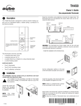
NOTE: Connect the wires using the provided solderless connectors for copper wires.
Wiring diagrams
Power
Load
Power
Load
120S / 240D models
240S model
Black
Black
Red
White (120S)
Red (240D)
400-114-029-A (Honeywell TH114-A_AF-120S_240S_240D) 5 x 3.125 EFS.book Page 7 Friday, August 27, 2010 4:10 PM

Owner’s Guide
8
ENGLISH
Insert the floor sensor cable through one of the two
openings on the wallplate and connect the sensor
wires to terminals 3 and 4 (no polarity).
• The sensor wires must not come in contact with the
electrical wires and must be routed outside the
electrical box and follow the wall down to the floor.
• Position the sensor cable such that it does not come in
contact with the floor heating wires. The sensor must
be centered between two floor heating wires for best
temperature control.
• Do NOT staple the sensor head (the plastic end) to the
floor. Doing so might damage the sensor. Any damage
might not be noticeable during testing but can become
apparent several days later.
If you wish to connect a remote control device (see
page 11), insert the wires (use 18- to 22-gauge
flexible wires) through one of the two openings on the
wallplate and connect them to terminals 1 and 2 (no
polarity).
Connecting the floor temperature sensor / remote control system
Floor
temperature
sensor
Remote
control
device
400-114-029-A (Honeywell TH114-A_AF-120S_240S_240D) 5 x 3.125 EFS.book Page 8 Friday, August 27, 2010 4:10 PM

TH114-A/AF-120S/240S/240D
9
ENGLISH
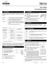
Configuration switches are on the back of the faceplate.
* See page 3 for definition of each mode.
- To select the F Mode, connect the floor temperature
sensor (see page 8) and place the switch in the F position.
- To select the AF Mode, proceed as follows: Connect the
floor temperature sensor (see page 8). Place the switch in
the F position. If the thermostat displays Er, the sensor is improperly connected or damaged. If the
thermostat displays a temperature reading, place the switch in the AF position.
- To select the A Mode, place the switch in the AF position but do NOT connect the floor temperature
sensor.
Setting the configuration switches
# Configurations Up Down
S1 Displayed temperature unit °F °C
S2 Temperature control mode * F AF
400-114-029-A (Honeywell TH114-A_AF-120S_240S_240D) 5 x 3.125 EFS.book Page 9 Friday, August 27, 2010 4:10 PM

Owner’s Guide
10
ENGLISH
The minimum and maximum floor temperature limits are available only if the temperature control mode is AF (see page 9).
If the floor temperature drops below the minimum limit or rises above the maximum limit, the thermostat will turn heating On
or Off respectively, regardless of the ambient temperature, to maintain the floor temperature within the set limits.
NOTE: The desired ambient temperature might not be attainable if the maximum floor temperature is set too low.
The minimum and maximum floor temperature limits are factory-set at 10 °C (50 °F) and 28 °C (82 °F) respectively. To
modify the limits, proceed as follows:
WARNING: To avoid damaging your floor, follow your floor supplier’s recommendations regarding floor temperature limits.
Switch the thermostat to Off or Standby.
While pressing either button, switch the thermostat back to On to access the floor temper-
ature limit settings.
Press the Backlight button briefly to switch between minimum and maximum floor temperature
settings.
Press the buttons to set the desired limit.
Press the Backlight button for 3 seconds to save your modifications. After the data are saved,
the thermostat displays the current temperature or “– –”.
NOTE: Your modifications are automatically saved if no button is pressed for 60 seconds.
Floor temperature limits (AF mode only)
400-114-029-A (Honeywell TH114-A_AF-120S_240S_240D) 5 x 3.125 EFS.book Page 10 Friday, August 27, 2010 4:10 PM

TH114-A/AF-120S/240S/240D
11
ENGLISH
The Unoccupied Mode can be activated if you have connected the thermostat to a
remote control device equipped with a dry contact (see page 8). When the contact
closes, the Unoccupied Mode is activated and
appears on the screen. In this
mode, the thermostat lowers its setpoint by 3.5 °C (7 °F) and all temperature
adjustments are blocked except for temporary bypass.
Temporary Bypass
You can temporarily bypass the Unoccupied Mode by pressing the backlight but-
ton. During the bypass,
flashes. The bypass is automatically cancelled after 2
hours or if the backlight button is pressed again.
Unoccupied Mode
400-114-029-A (Honeywell TH114-A_AF-120S_240S_240D) 5 x 3.125 EFS.book Page 11 Friday, August 27, 2010 4:10 PM

Owner’s Guide
12
ENGLISH
The measured temperature is below the display range. Heating is
activated.
The measured temperature is above the display range. Heating is
deactivated.
Verify the thermostat and sensor connections. Heating is deactivated.
Error Messages
400-114-029-A (Honeywell TH114-A_AF-120S_240S_240D) 5 x 3.125 EFS.book Page 12 Friday, August 27, 2010 4:10 PM

TH114-A/AF-120S/240S/240D
13
ENGLISH
Setpoint range - F mode: 5 °C to 40 °C (40 °F to 104 °F)
- A/AF mode: 5 °C to 30 °C (40 °F to 86 °F)
Floor limit range - AF mode: 5 °C to 40 °C (40 °F - 104 °F)
Display range - F mode: 0 °C to 60 °C (32 °F to 140 °F)
- AF mode: 0 °C to 50 °C (32 °F to 122 °F)
Resolution: 0.5 °C (1 °F)
Heating cycle length: 15 minutes
Data protection: All settings are saved during a power failure.
Technical Specifications
Model Supply Maximum current Maximum wattage Wiring
120S 120 VAC, 50/60Hz 16.7 A 2000 W 4 wires / single pole
240S
240 VAC, 50/60Hz
208 VAC, 50/60Hz
16.7 A
4000 W
3470 W
4 wires / single pole
240D
240 VAC, 50/60Hz
208 VAC, 50/60Hz
15 A
3600 W
3120 W
4 wires / double pole
400-114-029-A (Honeywell TH114-A_AF-120S_240S_240D) 5 x 3.125 EFS.book Page 13 Friday, August 27, 2010 4:10 PM

Owner’s Guide
14
ENGLISH
Honeywell warrants this product, excluding battery, to be free from defects in the workman-
ship or materials, under normal use and service, for a period of three (3) years from the date
of purchase by the consumer. If at any time during the warranty period the product is deter-
mined to be defective or malfunctions, Honeywell shall repair or replace it (at Honeywell's
option).
If the product is defective,
(i) return it, with a bill of sale or other dated proof of purchase, to the place from which you
purchased it, or
(ii) contact Honeywell. Honeywell will make the determination whether the product should
be returned, or whether a replacement product can be sent to you.
This warranty does not cover removal or reinstallation costs. This warranty shall not apply if
it is shown by Honeywell that the defect or malfunction was caused by damage which
occurred while the product was in the possession of a consumer.
Warranty
400-114-029-A (Honeywell TH114-A_AF-120S_240S_240D) 5 x 3.125 EFS.book Page 14 Friday, August 27, 2010 4:10 PM

TH114-A/AF-120S/240S/240D
15
ENGLISH
Honeywell's sole responsibility shall be to repair or replace the product within the terms
stated above. HONEYWELL SHALL NOT BE LIABLE FOR ANY LOSS OR DAMAGE OF
ANY KIND, INCLUDING ANY INCIDENTAL OR CONSEQUENTIAL DAMAGES RESULT-
ING, DIRECTLY OR INDIRECTLY, FROM ANY BREACH OF ANY WARRANTY, EXPRESS
OR IMPLIED, OR ANY OTHER FAILURE OF THIS PRODUCT. Some provinces, states or
regions do not allow the exclusion or limitation of incidental or consequential damages, so
this limitation may not apply to you.
THIS WARRANTY IS THE ONLY EXPRESS WARRANTY HONEYWELL MAKES ON THIS
PRODUCT. THE DURATION OF ANY IMPLIED WARRANTIES, INCLUDING THE WAR-
RANTIES OF MERCHANTABILITY AND FITNESS FOR A PARTICULAR PURPOSE, IS
HEREBY LIMITED TO THE THREE-YEAR DURATION OF THIS WARRANTY. Some prov-
inces, states or regions do not allow limitations on how long an implied warranty lasts, so the
above limitation may not apply to you.
This warranty gives you specific legal rights, and you may have other rights which vary from
one province, state or region to another.
400-114-029-A (Honeywell TH114-A_AF-120S_240S_240D) 5 x 3.125 EFS.book Page 15 Friday, August 27, 2010 4:10 PM

400-114-029-A (Honeywell TH114-A_AF-120S_240S_240D) 5 x 3.125 EFS.book Page 16 Friday, August 27, 2010 4:10 PM

TH114-A/AF-120S/240S/240D
7
FRANÇAIS
NOTA : Relier les fils en utilisant des connecteurs sans soudure pour fils de cuivre.
Schémas de branchement
Modèles 120S / 240D
Modèle 240S
Alimentation
Alimentation
Noir
Rouge
Charge
Charge
Noir
Blanc (120S)
Rouge (240D)
400-114-029-A (Honeywell TH114-A_AF-120S_240S_240D) 5 x 3.125 EFS.book Page 7 Friday, August 27, 2010 4:10 PM

400-114-029-A (Honeywell TH114-A_AF-120S_240S_240D) 5 x 3.125 EFS.book Page 16 Friday, August 27, 2010 4:10 PM
/