275
Zusatzanleitung
Additional Instructions
Elektropneumatisch schaltbare Mehrweite über Taster
Electropneumatically adjustable fullness by button
Page is loading ...
Page is loading ...
Page is loading ...
Page is loading ...
Page is loading ...
Page is loading ...
Page is loading ...

Foreword
This instruction manual is intended to help the user to become familiar
with the machine and take advantage of its application possibilities in
accordance with the recommendations.
The instruction manual contains important information on how to
operate the machine securely, properly and economically. Observation
of the instructions eliminates danger, reduces costs for repair and
down-times, and increases the reliability and life of the machine.
The instruction manual is intended to complement existing national
accident prevention and environment protection regulations.
The instruction manual must always be available at the
machine/sewing unit.
The instruction manual must be read and applied by any person that is
authorized to work on the machine/sewing unit. This means:
– Operation, including equipping, troubleshooting during the work
cycle, removing of fabric waste,
– Service (maintenance, inspection, repair and/or
– Transport.
The user also has to assure that only authorized personnel work on
the machine.
The user is obliged to check the machine at least once per shift for
apparent damages and to immediatly report any changes (including
the performance in service), which impair the safety.
The user company must ensure that the machine is only operated in
perfect working order.
Never remove or disable any safety devices.
If safety devices need to be removed for equipping, repairing or
maintaining, the safety devices must be
remounted directly after completion of the maintenance and repair
work.
Unauthorized modification of the machine rules out liability of the
manufacturer for damage resulting from this.
Observe all safety and danger recommendations on the machine/unit!
The yellow-and-black striped surfaces designate permanend danger
areas, eg danger of squashing, cutting, shearing or collision.
Besides the recommendations in this instruction manual also observe
the general safety and accident prevention regulations!

General safety instructions
The non-observance of the following safety instructions can cause
bodily injuries or damages to the machine.
1. The machine must only be commissioned in full knowledge of the
instruction book and operated by persons with appropriate
training.
2. Before putting into service also read the safety rules and
instructions of the motor supplier.
3. The machine must be used only for the purpose intended. Use of
the machine without the safety devices is not permitted. Observe
all the relevant safety regulations.
4. When gauge parts are exchanged (e.g. needle, presser foot,
needle plate, feed dog and bobbin) when threading, when the
workplace is left, and during service work, the machine must be
disconnected from the mains by switching off the master switch or
disconnecting the mains plug.
5. Daily servicing work must be carried out only by appropriately
trained persons.
6. Repairs, conversion and special maintenance work must only be
carried out by technicians or persons with appropriate training.
7. For service or repair work on pneumatic systems, disconnect the
machine from the compressed air supply system (max. 7-10 bar).
Before disconnecting, reduce the pressure of the maintenance
unit.
Exceptions to this are only adjustments and functions checks
made by appropriately trained technicians.
8. Work on the electrical equipment must be carried out only by
electricians or appropriately trained persons.
9. Work on parts and systems under electric current is not permitted,
except as specified in regulations DIN VDE 0105.
10. Conversion or changes to the machine must be authorized by us
and made only in adherence to all safety regulations.
11. For repairs, only replacement parts approved by us must be used.
12. Commissioning of the sewing head is prohibited until such time
as the entire sewing unit is found to comply with EC directives.
It is absolutely necessary to respect
the safety instructions marked by these signs.
Danger of bodily injuries !
Please note also the general safety instructions.

1. General
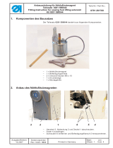
This optional equipment makes it possible to switch the fullness of the upper feed foot of the sewing
machine on and off by pushing a button (compare Operating Instructions for the sewing machine).
The sewing machine is already prepared for the mounting of the pneumatic cylinder and the solenoid
valve.
The individual components of the assembly (Order no. 0275 590044) can be seen in the exploded view
on page 9.
Attention!
Turn the main switch off! Change kit only with the sewing machine turned off.
Installation is to be carried out by trained personal only.
2. Pre-assembly of the Pneumatic Cylinder
The pneumatic cylinder 0999 00220715 with its components can be seen in the view on page 9.
–
Remove the hex nut which may be screwed onto the neck of the cylinder.
–
Screw on block 0275 310550 and secure with the lock nut.
–
Screw in the connection nipple 0797 002016 for the hose nozzle and the sound absorber
9710 982003.
3. Mounting of the Pneumatic Cylinder
–
Tilt up the sewing machine - the attachment points for the cylinder and the solenoid valve become
accessable.
The pneumatic cylinder is mounted vertically in the current position of the sewing machine - the bearing
eye on the cylinder base lies at the top.
In the working position, when the sewing machine is tilted back, the pneumatic cylinder lies horizontal.
(The drawing shows the position of the assembly components in their later working position after
completion of the mounting.)
–
Push the bearing eye at the cylinder base onto the attachment bolt.
–
Push the attachment block on the piston rod onto the attachment bolt.
–
Secure both attachments with the enclosed locking rings 0255 000129.
4. Mounting of the Solenoid Valve
The solenoid valve is preassembled; it is screwed tight on the support bracket 0271 001742 with the
screws of the lifting magnet 0271 001746.
–
Remove the belt guard on the right side of the sewing machine as described in the Operating
Instructions for the sewing machine.
–
Attach plug 9870 272002 to the solenoid valve and screw tight.
Elektropneumatisch schaltbare Mehrweite über Taster
Electropneumatically adjustable fullness by Push button
5
0275 590044
GB

–
Open the lower cover of the sewing machine distributor box.
–
Push the terminal plugs of the connection cable from the solenoid valve onto the positions 7 and 8
(assignment is random).
–
Close the lower cover of the sewing machine distributor box.
5. Connection of the Compressed Air Hoses
Note:
Position hoses for air pressure in such way that they will n ot be kinked or damaged by
moving parts.
Avoid any foot traps and obstacles in the working area.
–
Plug compressed air hose PU3 onto the connection on the throttle valve 9710 920011 of the
solenoid valve.
–
Lay compressed air hose PU3 through the angle bracket of the foot lift magnets to hose nozzle
0797 002016 of the pneumatic cylinder.
–
Shorten the hose and plug onto the hose nozzle of the pneumatic cylinder.
–
Check that the compressed air hose cannot be damaged by moving parts!
The compressed air supply of the sewing machine pneumatics is set for an operating pressure of 6 bar.
–
Plug compressed air hose PU3 for the compressed air supply onto the supply connection of the
solenoid valve 9710 061200.
–
Lay compressed air hose PU3 up to the compressed air supply and connect.
6. Change push button
The black key head present in the keypad must be replaced by the
key head with the “Fullness ” symbol printed on it.
7. Setting
During the seting work the sewing machine must be ready for
operation - it, however, remains in its tilted-back position so that
the setting screw on the throttle valve is accessable.
–
Reattach the belt guard and other removed parts.
–
Turn the machine on and turn on the compressed air supply.
–
Set the throttle valve 9710 920011 on the solenoid valve so that the resetting of the fullness control
is dampened.
–
To check the setting repeatedly operate the keys for triggering the fullness.
Elektropneumatisch schaltbare Mehrweite über Taster
Electropneumatically adjustable fullness by Push button
6
0275 590044

8. Fullness Activation Function Description.
The controls of the sewing drive have 2 function modules, which can be selected via parameters, for the
activation of fullness.
Further information is to be found in the Operating Instructions (271 - 275 Direct drive Section
Chapter ) and in the Parameter Sheet 9800 331101 PB11
8.1 Function Module “Fullness Activation with Speed Limitation ”
–
Activate the function module “Fullness Activation with Speed Limitation”. (Setting see Parameter
Table 8.1.1 Line A)
–
Fullness is deactivated when the mains are switched ON.
–
Fullness can be activated at any time by operating the “Fullness” key (Illus. 1). This is indicated by
the LED x in the x key being lit.
–
With fullness activated the maximum speed of the machine is limited. The level of the speed
limitation is set with a parameter (Setting see Parameter Table 8.1.1 Line B) (preset value). If no
speed limitation is required, the value of the maximum speed value (e.g. 4800) can be set.
–
Fullness can be deactivated again at any time through renewed operation of the “Fullness” key
(Illus. 1). The speed limitation is cancelled at the same time.
–
Attention! With fullness activated the beginning and manual bartack are sewn without fullness, after
the beginning bartack, sewing occurs with fullness.
–
Attention! With fullness activated the drive stops briefly at the beginning of the end bartack (as with
a decorative stitch bartack), then the end bartack and thread trimming are conducted without
fullness.
–
At this parameter setting (Setting see Parameter Table 8.1.1 Line C) the next seam after thread
trimming automatically begins with fullness.
–
At this parameter setting (Setting see Parameter Table 8.1.1 Line D) the next seam after thread
trimming begins without fullness, as when the mains are turned ON.
8.1.1 Parameter Table
for Function Module “Fullness Activation with Speed Limitation”
A
B
C
D
Function
Function module “Fullness Activation with Speed Limitation”
Speed limitation with fullness activated.
At this parameter setting the next seam after thread trimming
automatically begins with fullness.
At this parameter setting the next seam after thread trimming begins
without fullness, as when the mains are turned ON.
Parameters of the controls
DA220C DA40MS
F-250 = 2 510 = 2
F-289 586
F-251= OFF 515 = II
F-251 = ON 515 = I
Elektropneumatisch schaltbare Mehrweite über Taster
Electropneumatically adjustable fullness by Push button
7
0275 590044
GB

8.2 Function Module “Fullness Activation without Speed Limitation”
–
Activate the function module “Fullness Activation without Speed Limitation”. (Setting see Parameter
Table 72.1 Line A)
–
Fullness is deactivated when the mains are switched ON, indicated by illumination of the LED in the
key.
–
Fullness can be activated at any time by operating the “Fullness” key (Illus. 1),
–
Fullness can be activated again at any time through renewed operation of the “Fullness” key (Illus.
1)..
–
Attention! With fullness activated no manual bartack can be sewn.
–
Attention! With fullness activated the beginning and manual bartack are sewn without fullness, after
the beginning bartack, sewing occurs with fullness.
–
Attention! With fullness activated the drive stops briefly at the beginning of the end bartack (as with
a decorative stitch bartack), then the end bartack and thread trimming are conducted without
fullness.
–
At this parameter setting (Setting see Parameter Table 7.2.1 Line B) the next seam after thread
trimming automatically begins without fullness..
–
At this parameter setting (Setting see Parameter Table 7.2.1 Line C) the next seam after thread
trimming begins without fullness, as when the mains are turned ON
8.2.1 Parameter Table
for Function Module “Fullness Activation without Speed Limitation”
A
B
C
Function
Function module “Fullness Activation without Speed Limitation”
At this parameter setting the next seam after thread trimming
automatically begins without fullness.
At this parameter setting the next seam after thread trimming begins
with fullness, as when the mains are turned ON.
Parameters of the controls
DA220C DA40MS
F-250 = 3 510 = 3
F-251= OFF 515 = II
F-251 = ON 515 = I
Elektropneumatisch schaltbare Mehrweite über Taster
Electropneumatically adjustable fullness by Push button
8
0275 590044

9
Elektropneumatisch schaltbare Mehrweite über Taster
Electropneumatically adjustable fullness by Push button
GB
D

DÜRKOPP ADLER AG
Potsdamer Str. 190
33719 Bielefeld
Germany
Phone: +49 (0) 521 925 00
E-Mail: [email protected]m
www.duerkopp-adler.com
Subject to design changes - Part of the machines shown with additional equipment - Printed in Germany
© Dürkopp Adler AG - Original Instructions - 0791 275683 - 01.0 - 08/1999
/

