Page is loading ...

1
Brief introduction
Many thanks for purchasing Gigabit optical converter!
This product supports IEEE802.3Z/AB 1000Base-SX/LX
protocol, the working mode of duplex full mode and half
mode. The electric outlet is adaptive to the rate of
10/100/1000M Gigabit optical converter. This manual is
for various models of adaptive 10Base-T, 100Base-T, and
1000Base-T optical converters. The following purchasing
guide is for customer to refer to.
Purchasing guide for Gigabit optical converters
Model
Specifications
TP ←→SC/FC/ST
MM
10/100/1000M, multi-mode 500 meter,
SC/FC/ST
TP ←→SC/FC/ST
SM
10/100/1000M, single mode 0-80 Km,
SC/FC/ST
TP←→LC SM/MM
10/100/1000M, SFP slot
Packing list
Please check the following items in the package before
the installation of converter.
Gigabit optical converter 1 piece
Power line (build-in) 1 piece
User manual 1 copy
Please contact the dealer immediately for any loss or
damage to the above items.
Installation
1. Interface
RJ-45 interface
The transmission media adopts CAT5 and CAT 6
twisted-pair. It is recommended to use quality RJ-45 and
well made jumper. It features the function of
automatically identifying the through line and cross wire.
Fiber interface
The SC fiber interface is of duplex mode type, including
two interfaces, namely TX and RX. When the two sets of
optical converter are interfaced or connected to
switchboard with fiber interface, the fiber is in cross
connection, namely "TX-RX" "RX-TX".
2. Connection
Connect the network device (work station, hub or switch)
to the RJ-45 jack of the optical converter through
twisted-pair CAT5. Connect the multi-mode/single-mode
fiber to SC/ST/LC fiber interface of the optical
transceiver. Turn the power on. The corresponding LED
is on for a correct connection. (See the table below for the
LED indicator lamp)
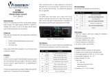
Figure 1 Schematic drawing of connection
Explanation for LED indicator lamp
The LED indicator lamps serve as device monitoring and
error display. The following explains each LED indicator.
LED
Status
Explanation
FDX
On
Converter works in the full duplex mode.
Off
Converter works in the half duplex mode.
FXLINK/ACT
Blink
Active status display of fiber interface
link
“Blink” indicates packet goes through
FX
1000
On
Rate of electrical interface is 1000Mbps
100
On
Rate of electrical interface is 100Mbps
TPLINK/ACT
Blink
Active status display of electrical
interface link
“Blink” indicates packet goes through
TP
PWR
On
Power is on and normal.
When both 1000 and 100 are Off, Rate of electrical interface is
10Mbps.

2
Fiber transmission features:
Product
model
Optical
wavelength
(nm)
Optical
power
(dbm)
Sensibility
(dbm)
Transmission
distance
TP- MM
850nm
-3~-10.5
≤-20
62.5μm:220meter
50μm:550meter
TP- SM
1310nm
0~-8
≤-21
20Km
TP- SM
1550nm
DFB
-3~-10
≤-24
40Km
TP- SM
1550nm
DFB
1~-6
≤-26
60Km
TP- SM
1550nm
DFB
4~-2
≤-26
80Km
Technical parameters:
1. Standard Protocol:
IEEE802.3Z/AB 1000Base-T/SX/LX
2. Transfer rate: Electrical interface: 10/100/1000Mbps
Fiber interface: 1.25Gbps
3 Interface: One UTP RJ-45 interface
One SC interface
4. Operation mode: full duplex mode or half duplex mode
5. Power supply parameter:
Build in: 90-264V AC 48VDC
External: 5V DC 2A
6. Environmental temperature: -20℃-70 ℃
7. Relative humidity: 5%-90%
8. TP cable: 5E, CAT 6
9. Transfer fiber: multi-mode: 50/125, 62.5/125μ m
single mode:: 8.3/125, 8.7/125, 9/125 or 10/125μ m
10 Dimensions:
Built-in power supply: 32mm x 127mm x 156mm
External power supply: 26mm x 71mm x 94mm
DIP-Switch:
*Toggle ON pin 1 to LFP is enable; OFF is disable
*PIN2 and PIN3 are set the MC operation mode
pin3
Pin2
ON
OFF
ON
Pass through
Smart pass through
OFF
Modified cut
through
Store and
forward(default)
Cautions:
1. This product is suitable for indoor application.
2. Put on the dust cover of fiber interface when not used.
3. It is forbidden to stare at the TX fiber-transfer end with
naked eyes.
4. Single optical fiber transceiver must be used in pair
Trouble shooting:
1. Line loss is excessive during the fiber wiring
Excessive loss in adaptor connector plug-in and fiber
soldering welding and excessive intermediate nodes may
cause excessive loss rate or abnormal operation.
2. If power loss is excessive in the fiber, please check and
clean the fiber patch cord connectors.
Gigabit Optical Converter
10/100/1000Base-Tx to 1000Base-X
User manual
(Please read before using the Media Converter)
/