Page is loading ...

DVR User Manual

1
1. PRECAUTIONS
Please observe the following precautions to avoid damage or data loss caused by improper
operation.
The DVR will work properly when used within the specified temperature and humidity levels.
Do not install the DVR in a dusty, humid, or smoky environment.
This device requires a stable, flat surface for proper operation.
Do not block the DVR’s ventilation openings.
Install only according to the instructions.
Do not spill liquid of any kind on this device.
Do not put any other equipment on top of this device.
Do not attempt to repair this DVR yourself, please refer all repair to a qualified technician.
Only use a Hard Disk Drive specified by the manufacturer with this DVR.
2. NOTES
This User Manual is for reference only and only applies to the products in this manual.
Updates to this manual or to the product may occur without notification.
The pictures shown may not be of the same product, and are for illustration purposes only.
Please contact Customer Service if you have any questions or want to upgrade to the latest support
software.
The default setting of the DVR is NTSC.

2
CONTENT
1. PRECAUTIONS ...................................................................................................................................... 1
2. NOTEs ...................................................................................................................................................... 1
3. PRODUCT INTRODUCTION ................................................................................................................ 4
3.1. introduction ................................................................................................................................ 4
3.2. FEATURES ............................................................................................................................... 4
3.3. INSTALLATION ........................................................................................................................ 5
3.4. PANEL INTRODUCTION ....................................................................................................... 8
3.5. MOUSE .................................................................................................................................... 13
3.6. INPUT METHOD .................................................................................................................... 14
3.7. POWER ON/OFF ................................................................................................................... 15
3.8. menu ICONs ........................................................................................................................... 17
3.9. LIVE VIEW .............................................................................................................................. 18
3.10. RIGHT BUTTON MeNU ........................................................................................................ 19
3.11. MAIN MENU INTRODUCTION ............................................................................................ 23
3.12. main menu > the SEARCH menu ........................................................................................ 24
3.13. main menu > the CONFIGURATION menu ....................................................................... 27
3.14. MAIN menu > the STORAGE menu ................................................................................... 44
3.15. main menu > the OUTPUT menu ........................................................................................ 55
3.16. main menu > the MAINTenance menu ............................................................................... 60
3.17. main menu > the SHUTDOWN menu ................................................................................. 63
4. WEB & CLIENT ..................................................................................................................................... 64
4.1. WEB OPERATION................................................................................................................. 64
5. FUNCTIONs .......................................................................................................................................... 72
5.1. DDNS Function ...................................................................................................................... 73
5.2. Port mapping .......................................................................................................................... 76

3
5.3. the NTP function .................................................................................................................... 78
5.4. Pan/Tilt/Zoom ......................................................................................................................... 79
5.5. Voice Intercom ........................................................................................................................ 84
5.6. Hard Disk redundancy ........................................................................................................... 84
5.7. HDD S.M.A.R.T ...................................................................................................................... 85
5.8. dvr firmware update: .............................................................................................................. 87
5.9. TERMS .................................................................................................................................... 88
5.10. HDD CAPACITY CALCULATION ....................................................................................... 89
5.11. Common Faults ...................................................................................................................... 92
Appendix1. Remote control operation ....................................................................................................... 95

4
3. PRODUCT INTRODUCTION
3.1. INTRODUCTION
This Digital Video Recorder (DVR) is an excellent digital surveillance product which uses H.264
video compression, hard disk recording, TCP/IP transmission, and a Linux-based Operating
System. It also uses advanced technologies that produce a more stable, reliable and higher quality
video image. This DVR supports synchronized video and audio recording, playback, and monitoring.
This series also supports network-based system control, as well as excellent network streaming
capabilities.
This manual is for both the 4-camera and 8-camera DVR models.
3.2. FEATURES
LIVE VIEW
CVBS interface, VGA synchronous output.
COMPRESSION
H.264 video compression, G.711 audio compression, supports D1-30 fps resolution.
RECORDING
Recording modes include manual, timed, alarm, and motion detection. It supports SATA hard disks
and local disk S.M.A.R.T. technology. This DVR also supports USB backup and Internet backup.
PLAYBACK
Playback can be viewed in several ways including local and network playback, multiple channels,
and simultaneous playback. There is also support for accelerated or slow motion viewing, rewind,
and frame by frame mode. Specific time playback is also supported.
CAMERA CONTROL AND ALARM
Remote camera control, multi-channel alarm input interface for connecting various types of alarm
equipment, motion detection alarm, video loss alarm, masking alarm, multi-channel alarm output,
alarm linkage, and on-site lighting control.
COMMUNICATION INTERFACE
Utilize USB 2.0 high-speed interface for connecting various backup devices, and a standard
Ethernet interface which works with various networks.

5
NETWORK PROTOCOLS
Supports TCP/IP, UDP, RTP/RTSP, DHCP, PPPOE, DDNS, NTP etc. Supports network real-time
live viewing, recording, playback, and camera control. Built-in Web Server, IE browser for direct
access.
OPERATION
You can control the system using the front panel and the supplied remote control or mouse.
3.3. INSTALLATION
3.3.1. CHECK DVR AND ACCESSORIES
When you unpack the DVR, you should find the following items in the box. If anything is missing
please notify your place of purchase.
• Digital Video Recorder
• AC/DC adapter
• USB MOUSE
• Remote Control
• Hard Disk Mounting Hardware Packet
• User Manual
• Quick Start Guide
• Support CD

6
3.3.2. HARD DISK INSTALLATION
Tools & Preparation
You will need a Philips-head screwdriver and a hard disk drive to install inside the DVR housing.
Hard Disk Specifications: 3.5-inch SATA hard disk drive (maximum capacity is 2TB).
Installation Steps
Make sure to take precautions against static electric discharge when installing the hard disk. Static
discharge could damage the drive and the internal components of the DVR. To reduce this risk, it is
best to work on an anti-static mat and use a grounding wrist strap.
1. Use a Philips-head screwdriver to remove the DVR’s outer metal housing by removing the two
screws on each side of the housing and the one at the upper back edge. Set the screws aside to be
used for reassembly.
2. The hard disk will have mounting holes on the underside of the drive and these should line up
with the mounting holes in the bottom of the DVR. Orient the drive so that the power and data cable
connectors are facing the front of the DVR and align the mounting holes on the hard disk with the
mounting holes in the bottom of the DVR.
Use the supplied screws to fasten the hard disk to the DVR’s metal frame by inserting the screws
from the outside of the DVR through the housing and then screw them into the hard disk’s mounting
holes. To avoid undesirable results it is important that the hard disk be securely mounted to
the DVR.
3. Connect the power and data cables from the DVR circuit board to the hard disk. The connectors
are of different sizes and are keyed for easy and correct placement.
4. Replace the DVR outer housing and secure it with the housing screws.
Note:
The capacity of the hard disk determines how much video can be recorded to the hard in addition to
whatever DVR parameters (recording or encoding setup) have been set to make the recording.
Refer to section 5.10 in Chapter 5 of this manual for more information.

7
3.3.3. SYSTEM INSTALLATION
Preparation
Before you integrate the DVR into a complete surveillance system, you will need to assemble all the
necessary components and connecting cables. These include cameras with their power adapter(s)
and connectors, a video display monitor to display the camera video feed, and connecting cables
for all devices.
Connecting the DVR to a System
To connect the DVR to the other components in a surveillance system you will need to do the
following:
Place the DVR on a flat stable surface and connect the cameras to the video input jacks on the back
panel.
Connect the VGA video output port to the system display monitor.
Connect a network cable to the RJ45 network interface for connecting to a LAN or other network.
Connect the supplied USB mouse to one of the USB 2.0 ports on the rear panel of the DVR.
Plug in the AC power adapter into the power jack on the rear panel of the DVR.
Caution:
For an external alarm device or PTZ camera, please refer to its relevant instructions.
The DVR power cords should be placed under all other wires and connected correctly.

8
3.4. PANEL INTRODUCTION
3.4.1. FRONT PANEL
Type A:
1 4 5 4 6 2 3 7
Index
Name
Function
1
Sign
DVR Logo
2
Indicators
Power On, Network Activity, Recording Active
3
IR/Ext.IR
Receives signals from the remote control
4
Function Keys
Function keys, and the corresponding number key to switch or exit
the function keys
5
Directional keys
Directional controls: Up/Down can jump up or down. Activates the
digital input box to increase or decrease a number.
Left/Right: Switches screens
Enter: Operation confirmation
Switches to default button
Menu configuration.
6
Menu
The Main Menu function key
7
USB
USB 2.0 Ports for mouse & external device

9
Type B:
1 2 3 4 5 6 7
DIAGRAM 3-1 FRONT PANEL FUNCTION
Index
Name
Function
1
Sign
DVR Logo
2
Indicators
Power On, HDD/Network /Alarm/Recording Active
3
Directional keys
Directional controls: Up/Down can jump up or down. Activates the
digital input box to increase or decrease a number.
Left/Right: Switches screens
Enter: Operation confirmation
Switches to default button
Menu configuration.
4
Function Keys
Function keys, and the corresponding number key to switch or exit
the function keys
5
IR/Ext.IR
Receives signals from the remote control
6
USB
USB 2.0 Ports for mouse & external device
7
Power key
Long press to power on/off DVR system.
FORM 3-1 FRONT PANEL DESCRIPTION

10
3.4.2. REAR PANEL
DIAGRAM 3-1 REAR PANEL INTERFACE FOR 4CH COMPACT CASE
DIAGRAM 3-2 REAR PANEL INTERFACE FOR 8CH COMPACT CASE
1
Video input
Analog video signal (BNC) input jacks
2
Audio input
Audio (RCA) input jacks
3
Video/Audio Output
Analog video/audio signal (BNC) output jacks
4
Net
RJ45 network cable connector
USB Ports
USB 2.0 Ports for mouse & external device
NOTE: The bottom USB port is not available.
5
VGA
VGA output port
6
Power input
DC 12V
7
RS-485 Port
A/B RS-485 port for P/T/Z (Pan/Tilt/Zoom) Connection
8
Power switch
Turn on/off the DVR main power.
TABLE 3-1: REAR PANEL FUNCTIONS
*The A and B connectors on the RS-485 port connect to A and B port connectors on a P/T/Z
decoder. A is the RS-485(+) terminal, B is the RS-485 (–) terminal. It uses a parallel circuit with

11
120Ω resistance at the A and B ports to reduce signal interference when there are several P/T/Z
decoders connected.
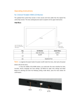
Rear Panel Instruction for 8/16CH 1U case:
Rear Panel Instruction for 4/8/16CH 1U case:
DIAGRAM 3-2 REAR PANEL FUNCTION

12
Index
Name
Description
1
Video input
Composite video signal (CVBS) input interface.
2
Audio input
Audio input interface.
3
HDMI
HDMI output interface.
4
VGA
VGA output interface.
5
Video/ Audio output
Composite video/audio signal (CVBS) output interface.
6
Ports
Alarm input/output, RS-485 interface.
7
USB/Network
USB2.0 and RJ-45 interface.
8
Power input
DC 12V.
9
Power switch
Turn on/off the DVR main power.
FORM 3-2 RARE PANEL FUNCTION
3.4.3. RARE PANEL I/O INTERFACE
DIAGRAM 3-33 8CH I/O INTERFACE DIAGRAM 3-44 16CH I/O INTERFACE
Index
Name
Description
1
Alarm input
Connection for external Alarm Peripherals(PIR Sensor,Alarm
Panel).
2
GND
Grounding.
3
Alarm output
Connection for external devices (Pezos, buzzer, siren).
4
RS-485
Communication terminal for Pan/Tilt/Zoom cameras.
Form 3-3 I/O Description

13
3.5. MOUSE
In addition to the front panel keys and remote control menu, you can also connect the mouse to a
USB port to control the On-Screen Display (OSD) menu functions. The following section describes
the mouse functions.
Click Left Button
If you are not logged in, a password entry dialog box will pop up. Enter a password and user-name
and then click ―OK‖ using the left mouse button to enter the Main menu during real-time monitoring.
Left click the mouse on the Options icon to enter the menu.
Click the exact instructions to control.
Change the state of check boxes and dynamic detection blocking.
Click the combo box and a drop-down list will pop up.
Under 3D P/T/Z control mode, click the mouse and drag to the lower right, this will enable 3D P/T/Z
control. Drag from the lower right to upper left to make 3D P/T/Z control narrow. For more details
refer to Section 5.4 P/T/Z.
Double-Click Left Button
Select and confirm or open, for example: double-click on playback video.
While in multi-screen view, double-click one channel to open that channel for full screen mode.
Double-click the screen again to return to multi-screen view.
Click Right Button
Pop up the context menu under the monitor screen.
Exit without saving while in the menu interface.
Scroll Wheel
Increase or decrease a value while in the Switch combo box options.
Move up and down in a list box.
Zoom in and out in P/T/Z 3D zoom mode.
Mouse Movement
Select and control the movement of the cursor.
Mouse Drag

14
Selects motion detection area.
Set up regional coverage area.
Select 3D P/T/Z zoom function.
3.6. INPUT METHOD
In the input box, choose numbers, symbols or uppercase and lowercase letters. Click the left mouse
button to select value; back arrow means backspace and the ―˽‖ is used to enter a space.
Letter Input Interface
DIAGRAM 3-5 LETTER INPUT INTERFACE
Number Input Interface
DIAGRAM 3-6 NUMBER INPUT INTERFACE
Special Symbols Input Interface
Diagram 3-7 SPECIAL SYMBOLS INPUT INTERFACE

15
3.7. POWER ON/OFF
3.7.1. POWER ON
If the DVR is installed correctly and the switch is set to ―ON‖ with the power light on, the DVR will
boot up automatically. Different models may have varying boot-up processes, please refer to the
Front Panel Introduction.
The DVR will detect all of the hardware connected to it when the power is turned ―on‖, the process
only takes approximately 20 seconds. After detection, the DVR will sound an alarm and enter into
multi-screen live view, which enables the user to start operation. Please refer to the Main Menu
Introduction or relevant instructions.
The Recording time includes the power-up time, because the DVR will automatically start counting
the recording when the power is switched on.
DIAGRAM 3-8 LIVE VIEW (OPERATION OF THE 4-CHANNEL DVR IS THE SAME AS THE 8-CHANNEL)
Note: The power supply must match the DVR, substituting is not recommended.
3.7.2. POWER OFF
Click on the SHUTDOWN button to turn off the DVR.
【Main Menu】→【Shutdown】→【Shutdown】.

16
DIAGRAM 3-9 TURN OFF DEVICE
Note: Turn DVR power off using the power switch if you plan to exchange the internal hard
disk.
3.7.3. OUTAGE RECOVERY
If you have to reboot after a power outage or forced shutdown, the DVR will have saved any files
before the power outage occurred and will return to the normal operation mode.

17
3.8. MENU ICONS
3.8.1. STATUS ICONS
:Record
:Video feed lost
:Motion detected
:Channel lock
:Allows screen to switch polling
3.8.2. OPERATION ICONS
:Not selected
:Selected
:Drop down menu
:Confirm changes/Enter a menu.
:Cancel changes/Cancel entering a menu
:Set parameters
:Save parameters
:Restores factory default settings or reverts to the last set of saved parameters
:Apply – applies the current settings
:Copy current settings to other channels
:Enter the configuration menu
:Configures alarm, video detection and trigger processing

18
3.9. LIVE VIEW
Turn the DVR on to enter live view mode. The date, time, channel names or icons will be displayed
and indicate the recording and alarm status on-screen.
You can switch display screens by using the DVR front panel, the remote control, or the USB
mouse.
When enabling on-screen messages for any external alarms, video loss, masking, motion detection,
or network and IP conflict alarms, the following interface should pop-up when any of those events
occur. Refer to
Diagram 3-10 Alarm STATUS
DIAGRAM 3-10 ALARM STATUS (for both 4 & 8 channel DVR operation)

19
3.10. RIGHT BUTTON MENU
Click the right mouse button after entering the real-time browser interface and a drop down menu
will appear, as shown in
Diagram 3-11 RIGHT BUTTON MENU.
DIAGRAM 3-11 RIGHT BUTTON MENU (for both 4- & 8-channel DVR operation)
3.10.1. SCREEN SWITCHING
A maximum of eight channels can be displayed on one monitor screen. The operator can choose to
display one, four, or eight channels.
3.10.2. PAN/TILT/ZOOM CONTROL
Select Output P/T/Z to set P/T/Z protocol, baud rate or address bits. For details on doing this,
refer to chapter 5.4.
3.10.3. COLOR SETTING MENU
/