
SPECIFICATIONS AND PARTS ARE SUBJECT TO CHANGE FOR IMPROVEMENT.
Multimedia LCD Projector
May 2004 Digital Media Division
YK
No.0546E
PJ-TX100
(C11H)
SERVICE MANUAL
Be sure to read this manual before servicing. To assure safety from fi re, electric shock, injury, harmful
radiation and materials, various measures are provided in this Hitachi Multimedia LCD Projector. Be
sure to read cautionary items described in the manual to maintain safety before servicing.
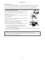
Caution
1. When replace the lamp, to avoid burns to your fi ngers. The lamp becomes too hot.
2. Never touch the lamp bulb with a fi nger or anything else. Never drop it or give it a shock. They may
cause bursting of the bulb.
3. This projector is provided with a high voltage circuit for the lamp. Do not touch the electric parts of
power unit (main), when turn on the projector.
4. Do not touch the exhaust fan, during operation.
5. The LCD module assembly is likely to be damaged. If replacing to the LCD LENS/PRISM assembly,
do not hold the FPC of the LCD module assembly.
6. Use the cables which are included with the projector or specifi ed.
Service Warning
Warning
The technical information and parts shown in this
manual are not to be used for: the development,
design, production, storage or use of nuclear, chemical,
biological or missile weapons or other weapons of
mass destruction; or military purposes; or purposes that
endanger global safety and peace. Moreover, do not
sell, give, or export these items, or grant permission for
use to parties with such objectives. Forward all inquiries
to Hitachi Ltd.
1. Features -----------------------------------------------2
2. Specifi cations -----------------------------------------2
3. Names of each part ---------------------------------3
4. Adjustment --------------------------------------------5
5. Troubleshooting ------------------------------------ 12
6. Service points -------------------------------------- 17
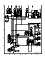
7. Wiring diagram ------------------------------------- 29
8. Disassembly diagram ----------------------------- 34
9. Replacement parts list ---------------------------- 37
10.RS-232C commands ----------------------------- 38
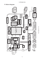
11. Block diagram -------------------------------------- 47
12. Connector connection diagram ---------------- 48
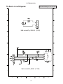
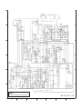
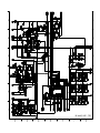
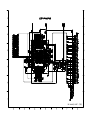
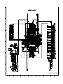
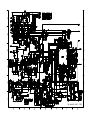
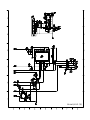
13.Basic circuit diagram ------------------------------ 49
Contents
Updated 4/21/05
Version 0546E.1

2
PJ-TX100(C11H)
1. Features
Super focus ED (Extra-low dispersion) lenses are adopted for the highest possible image quality.
720P wide LCD panels realize faithful reproduction of high-definition images.
Motorized iris control is provided for realizing film-like images with blacker black.
1.6x zoom lens and the optical lens shift allow flexible installation and viewing position.
2. Specifications
Liquid
Crystal
Panel
Drive system TFT active matrix
Panel size 1.8cm (0.7type)
Number of pixels 1280 (H) × 720 (V)
Lamp 150W UHB
Video Input System NTSC,PAL(BGDHI),SECAM,PAL-M,PAL-N,NTSC4.43,PAL60
Level Composite 1.0±0.1Vp-p(75Ωtermination)
S-Video Y : 1.0±0.1Vp-p(75Ωtermination)
C : 0.286±0.1Vp-p(NTSC burst signal,75Ωtermination)
0.3±0.1Vp-p
(PAL/SECAM burst signal,75Ωtermination)
Component Y : 1.0±0.1Vp-p(75Ωtermination)
C
B
/P
B
: 0.7±0.1Vp-p(75Ωtermination)
C
R
/P
R
: 0.7±0.1Vp-p(75Ωtermination)
RGB input /
output
Analog RGB 0.7V p-p (75Ωtermination)
Sync. TTL level
Power supply AC100~120V / 2.4A , AC220~240V / 1.3A
Power consumption 220W
Dimensions 340(W) × 110(H) × 280(D) mm (No including protruding parts)
Weight 4.4kg(9.7lbs)
Temperature Operation : 5~35°C Storage : -20~60°C
Accessories Power cord
PJ-TX100W x 3
(US, UK, Europe)
PJ-TX100E x 2 (UK, Europe)
PJ-TX100U x 1 (US)
Component cable x 1
Rivet (for Lens cap) x 1
Strap (for Lens cap) x 1
Remote control transmitter x 1
Battery (for Remote control) x 2
User’s manual
Quick guide x 1
Safety guide x 1
Operating guide book x 2 or 3

3
PJ-TX100(C11H)
3. Names of each part
Parts names
Projector
Lens
radiates powerful light for projecting an image.
Lens cover
Vertical
lens shift dials
Horizontal
lens shift dials
Filter cover
(An air fi lter is inside.)
Elevator button
is on the both sides.
Elevator foot
is on the both sides.
Remote sensor
Zoom knob
Focus knob
Exhaust vent
AC inlet
Power switch
Elevator button
DVI-D
Y
C
B
/P
B
C
R
/P
R
COMPONENT VIDEO
S-VIDEO
VIDEO
COMPUTER CONTROL
DVI-D port
COMPONENT
VIDEO ports
Y
C
B
/P
B
C
R
/P
R
VIDEO port
S-VIDEO port
COMPUTER
port
CONTROL port
Intake vent
Lamp cover
Strap hole
Elevator foot
Elevator foot
(Bottom of projector)
Elevator foot
Exhaust vent

4
PJ-TX100(C11H)
STANDBY/ON button
prepares for turning the power
on/off.
POWER indicator
tells the state of power supply.
MENU button
operates the menu function.
INPUT button
toggles between the
signal ports.
COMPONENT
VIDEO
S-VIDEO
VIDEO
DVI-D
COMPUTER
POWER
MENU
ENTER
LAMP
TEMP
STANDBY/ON
INPUT
RESET
TEMP indicator
lights or blinks when any problem about
internal temperature has happened.
LAMP indicator
light or blinks when any problem about
the lamp has happened.
Cursor buttons
works for adjusting or menu controlling.
ENTER button
proceeds to the next operation at the
menu functions.
RESET button
cancels the adjustment in progress.
* Note that the items whose functions
are performed simultaneously with
operating are nor reset.
POWER button
prepares for turning the
power on/off.
(the same as the
STANDBY/ON button above.)
OPT BLK button
toggles between the
modes for the optical black.
ASPECT button
toggles between the modes for
the aspect ratio.
Cursor buttons
(the same as the above.)
MENU button
(the same as the above.)
BRIGHT buttons
controls the brightness of the
whole screen.
DVI button
selects the DVI-D port input.
PC button
selects the COMPUTER port input.
COMPO button
selects the COMPONENT
VIDEO port input.
POWER LIGHT
OPT BLK
ASPECT
MENU
BRIGHT CONTRAST COLOR
IRIS
MODE
MEMORY
ENTER
RESET
DVI PC
AUTO
COMPO
S-VIDEO
VIDEO
LIGHT button
turn on/off the back light for
the remote control buttons.
MEMORY button
toggles between your
adjustments.
IRIS button
toggles between the modes
for the iris.
ENTER button
(the same as the above.)
RESET button
(the same as the above.)
CONTRAST buttons
controls the contrast of the
whole screen.
COLOR buttons
controls the color of the whole
screen.
AUTO button
executes automatic
adjustment.
VIDEO button
selects the VIDEO port input.
S-VIDEO button
selects the S-VIDEO port input.
MODE button
toggles between
the modes for the
picture type.
Remote control transmitter

5
PJ-TX100(C11H)
4. Adjustment
4-1 Before adjusting
4-1-1 Selection of adjustment
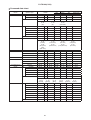
When any parts in the table 4-1 are changed, choose the proper adjusting items with the chart.
Table 4-1: Relation between the replaced part and adjustment
Replaced
part
Adjustment
Convergence
(Chap.4-2)
E-POS
(Chap.4-3)
Ghost
(Chap.4-4)
Flicker
(Chap.4-5)
NRSH
(Chap.4-6)
White
balance
(Chap.4-7)
Color
uniformity
(Chap.4-8)
AIR
SENSOR
(Chap.4-9)
IRIS
(Chap.4-10)
Dichroic
optics unit
LCD/LENS
prism
assembly
PWB
assembly
Main
Lamp
unit
assembly
PWB
assembly
Sensor
: means need for adjustment.
: means not need for djustment.
: means recommended.
4-1-2 Setting of condition before adjustment
1. Before starting adjustment, warim up projector
for about 10 minutes.
2. Set Zoom Wide to Max. And project an image
with more than 1m (40 inches) in diagonal size.
3. Set the lens position to the center, where you
feel click, using horizontal and vertical lens shift
dials.
4. Normalizing the video adjustment
Press the [MENU] button to display the Easy
menu. If Advance menu comes up, move to the
Easy menu.
Select RESET in the Easy menu and press [ ]
or [ENTER] button to open the RESET menu
window. Choose EXECUTE with [ ] button.
Note that no signal input may have the projector
reset its adjustments.
5. Select PICTURE > GAMMA in the Advanced
menu to set to DEFAULT1.
Note that PICTURE menu is not selectable with
no signal input displayed.
6. Select PICTURE > COLOR TEMP > CUSTOM
in the Advance menu, then press [ ] or [ENTER]
button to display the equalizing window. Set all
the values of OFFSET and GAIN in the window
to zero.
Caution: Before this performance, make a note
of your customer’s adjustments, because the
data is overwritten.
7. Perform all adjustments from the FACTORY
MENU.
Perform the following operations to display the
FACTORY MENU.
a. Press the [MENU] button of remote control to
display the Easy menu. (If the Advance menu
appears, move to the Easy menu from EASY
MENU.)
b. Select the [RESET] in the Easy menu, and
then press the [ ] or [ENTER] button.
c. Next, press the [RESET] button one time.
And hold the [RESET] button for 3 seconds
or more (the FACTORY MENU will appear).

6
PJ-TX100(C11H)
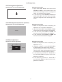
4-4 Ghost adjustment
Signals for internal adjustment
0/255
30%
112/255
30%
Adjustment procedure
1. Make this adjustment after completing the
adjustment in 4-3.
2.
Use DAC-P - GHOST - R: in the FACTORY MENU
to adjust so that R color ghost is at a minimum.
(Set the adjustment value to default, and then
raise the value. When a ghost appears to the left
of a vertical line, reduce the value by 4 steps.)
3. In the same way, use DAC-P - GHOST-G: in
the FACTORY MENU to adjust so that G color
ghost is at a minimum.
4. In the same way, use DAC-P - GHOST-B: in
the FACTORY MENU to adjust so that B color
ghost is at a minimum.
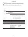
4-2 Convergence adjustment
Signal pattern for internal adjustment
Adjustment procedure
1. Open FACTORY MENU and then select
OPTION > CNV-V. Use R and/or B so that
three colors of images can be converged at
center, top and bottom of the screen.
2. In the same way, select OPTION > CNV-H and
use R and/or B so that three colors of images
can be converged at center, left and right of the
screen.
4-3
E-POS adjustment
(vertical bars adjustment)
Signal pattern for internal adjustment
112/255
Adjustment procedure
1. Make this adjustment after completing the
adjustment 4-2 Convergence adjustment.
2.
Open FACTORY MENU. Select DAC-P > E-POS
> R and use it so that vertical bars can disappear.
3. In the same way, select DAC-P > E-POS > G
and use it so that vertical bars can disappear.
4. In the same way, select DAC-P > E-POS > B
and use it so that vertical bars disappear.

7
PJ-TX100(C11H)
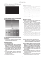
4-5 Flicker adjustment
(V.COM adjustment)
Signals for internal adjustment
Adjustment procedure
1. Make this adjustment after completing the
adjustment in 4-4 Ghost adjustment.
2.
Use DAC-P - V.COM - R: in the FACTORY
MENU to adjust so that the flicker at the center of
the screen is less than the flicker at the periphery.
(When the flicker is about the same across the
whole screen, adjust so that the flicker at the center
of the screen is somewhat less than elsewhere.)
3. In the same way, use DAC-P - V.COM-G: in the
FACTORY MENU to adjust the G color flicker.
4. In the same way, use DAC-P - V.COM-B: in the
FACTORY MENU to adjust the B color flicker.
4-7
White balance adjustment
(visual inspection)
Preparations
1. Perform these adjustments after the NRSH
adjustment described in Section 4-6.
2. Reset gamma correction before adjustment.
Place the cursor on [GAMMA] in the FACTORY
MENU, press the [RESET] key and select [DEFAULT].
Adjustment procedure
1. First, adjust the G color.
2.
Select GAMMA, SUB-CNT, and G: in the FACTORY
MENU. If the background is white solid, press the
[ENTER] key on the Remote control transmitter to
change to [G] monochrome in the 33-tone grayscale.
3. Adjust GAMMA, SUB-CNT, and G: in the FAC-
TORY MENU so that brightness of 33 steps is
best.
4. Don’t adjust GAMMA, SUB-BRT, and G: in the
FACTORY MENU. Because we want to keep
the best contrast ratio.
5. Then adjust colors R and B.
6.
Select GAMMA, SUB-CNT, and G: in the FACTORY
MENU. If the background is white solid, press the
[ENTER] key on the Remote control trasmitter to
change to [W] monochrome in the 33-tone grayscale.
7. Adjust GAMMA, SUB-BRT, R: and B: in the
FACTORY MENU so that low-brigtness white
balance is best.
8. Adjust GAMMA, SUB-CNT, R: and B: in the
FACTORY MENU so that middle-brightness
white balance is best.
9. Repeat steps 7 to 8 above, and adjust so that
brightness white balance of 33 steps is best.
4-6
NRSH adjustment (vertical stripe adjustment)
Signals for internal adjustment
64
/255
88
/255
112
/255
136
/255
160
/255
160
/255
136
/255
112
/255
88
/255
64
/255
Adjustment procedure
1. Make this adjustment after completing the
adjustment in 4-5 Flicker adjustment.
2. Use DAC-P - NRSH - R: in the FACTORY
MENU to adjust so that the vertical lines spaced
every 6 dots are as inconspicuous as possible.
(Reduce the adjustment value when black
stripes appear in the 2nd or 3rd tone from the
black side. Note that when the adjustment value
is lowered, white stripes may appear in the 2nd
or 3rd tone from the bright side. Should this
happen, adjust so that the stripes are as incon-
spicuous as possible.)
3.
In the same way, use DAC-P - NRSH - G: in the
FACTORY MENU to adjust vertical stripes of G color.
4.
In the same way, use DAC-P - NRSH - B: in the
Adjustment menu to adjust vertical stripes of B color.
Press ENTER key

8
PJ-TX100(C11H)
VID-AD
MIN
MID-L
MID-H
MAX
DAC-P
GAMMA
C. UNIF.
No. 1 R 0
STRIPE
OPTION
C.UNIF
ON/OFF ON
OFF
G 0 B 0
Major adjustment lattice point No.
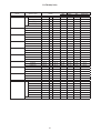
4-8 Color uniformity adjustment
Preparations
1.
Perform these adjustments after the white balance
adjustment described in Section 4-7.
2. Make a color uniformity adjustment for the follow-
ing four tones.
MIN tone (approx. 7% input signal)
MID-L tone (approx. 21% input signal)
MID-H tone (approx. 50% input signal)
MAX tone (approx. 75% input signal)
3. Place the cursor on [C.UNIF.] in the FACTORY
MENU and press the [ ] key. This displays the
Adjust Tone menu at the bottom of the screen.
To choose the tone to be adjusted, press the [ ]
key and then use the [ ] or [ ] key.
Select the major adjustment lattice point No.
and color, and then adjust them.
4. The major adjustment lattice point numbers (a
total of 17 points) corresponds to the major
adjustment lattice point positions in the diagram
on the right. The color uniformity of the entire
screen can be adjusted by adjusting the white
balance for each of the points starting in order
from the low numbers.
5. Adjustment point No.1 should not be adjusted,
because it controls the brightness of the entire
screen.
6.
To temporarily turn correction off, place the
cursor on [C.UNIF.] in the Adjust Tone menu and
press the [
] key. The ON/OFF menu appears.
Place the cursor on [ON] with the [ ] key and
press the [ ] key. To turn it on again, place the
cursor on [OFF] and press the [ ] key.
7. Although this adjustment can also be made
using internal signals, we will here use the
[ENTER] key on the Remote control transmitter
to select the following two signals.
Solid monochrome adjustment color (use G
color adjustment when a color differential
meter is used).
Solid white (use for adjustment other than
above).
8. Reset color-shading correction before adjust-
ment.
When 4 tones and all colors are to be reset,
place the cursor on [C.UNIF.] in the FACTORY
MENU, press the [RESET] key and select
[DEFAULT].
When only 1 tone is to be reset, place the
cursor on the tone to be reset, press the
[RESET] key and select [DEFAULT].
Single tone and monochrome resets cannot
be performed.
FACTORY MENU
Major adjustment lattice point position
14 12
13
16
15 17
6 4 8
2 1 3
7 5 9
10 11
V/6
H/6 H/3 H/3 H/6
V/3
V/3
V/6
Adjust tone menu

9
PJ-TX100(C11H)
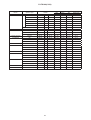
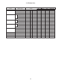
Adjustment procedure 1
(When a color differential meter is used)
1. First adjust [MID-L] tone [G:].
2. Select adjustment point [No.2][G:].
When the background is not [G] monochrome,
press the [ENTER] key on the Remote control
transmitter to change to solid [G] monochrome.
3. Measure the illumination at adjustment points
No. 2, No.3, No.10 and No.11.
The values should be:
No.2 = Y2 [lx] No.10 = Y10 [lx]
No.3 = Y3 [lx] No.11 = Y11 [lx]
4. No.2 and No.3 adjustment point have the aver-
age of Y2 and Y3.
Y2 = ( Y2 + Y3 ) / 2 ± 2 [%]
Y3 = ( Y2 + Y3 ) / 2 ± 2 [%]
5. No.10 and No.11 adjustment point have the
average of Y10 and Y11.
Y10 = ( Y10 + Y11 ) / 2 ± 2 [%]
Y11 = ( Y10 + Y11 ) / 2 ± 2 [%]
6. Then adjust [MID-L] tone [R] and [B].
When the background is [G] monochrome,
press the [ENTER] key on the Remote control
transmitter to change to solid white.
7. Measure the color coordinates of adjustment
point [No.1] and make a note of them.
Assume that they are x = x1, y = y1.
Note: When the CL-100 color and color differ-
ence meter is used, the [
](delta) mode
is convenient. When adjustment point
[No.1] color coordinate has been
selected, set the slide switch on the side
to [ ](delta) while holding down the [F]
button on the front panel. The measure-
ment shown after this displays the devia-
tion from measurement point 1.
8. Measure the color coordinates of measurement
point [No.2] and adjust [No.2][R:] and [B:] so
that the coordinates are as follows.
x = x1 ± 0.005 , y = y1 ± 0.010
9. Similarly, measure adjustment points [No.3] to
[No.17] and adjust their color coordinates start-
ing in order from the small number points.
This completes adjustments required for [MIN].
Note: Since excessive correction may lead to a
correction data overview during internal
calculations, use the following values for
reference.
[No.2] to [No.5] ± 40 or less
[No.6] to [No.9] ± 50 or less
[No.10] to [No.13] ± 70 or less
[No.14] to [No.17] ± 120 or less
10. Then adjust [MIN] tone [G] so that the adjust-
ment data set two times as much as [MID-L]
tone [G].
This completes [G] color adjustments.
11. Then adjust [MIN] tone [R] and [B].
Select [No.2] [B:] and press the [ENTER] key
on the Remote control transmitter to change to
solid white.
12. Measure the color coordinates of adjustment
point [No.1] and make a note of them.
Assume that they are x = x1, y = y1.
13. Now measure the color coordinates of mea-
surement point [No.2] and adjust [No.2][R:] and
[B:] so that the coordinates are as follows.
x = x1 ± 0.005 , y = y1 ± 0.010 (Target)
x = x1 ± 0.020 , y = y1 ± 0.040
14. Similarly, measure adjustment points [No.3] to
[No.17] and adjust their color coordinates start-
ing in order from the small number points.
This completes [MIN] tone adjustments.
15. Now make similar adjustments for [MID-H] tone.
(Adjust [MID-H] tone [G] so that the adjustment
data set half as many as [MID-L] tone [G].)
16. Now make similar adjustments for [MAX] tone.
(Adjust [MAX] tone [G] so that the adjustment
data set half as many as [MID-L] tone [G].)

10
PJ-TX100(C11H)
Adjustment procedure 2
(visual inspection)
1. First adjust [MIN] tone [G:].
2. Select [No.2] [G:].
If the background is [G] monochrome, press the
[ENTER] key on the Remote control transmitter
to change to solid white.
3. View measurement point [No.2] and [No.3].
Lower the [G] color intensity only of the color
point whose [G] color is more intense than
measurement point [No.1].
4. View measurement point [No.10] and [No.11].
Lower the [G] color intensity only of the color
point whose [G] color is more intense than
measurement point [No.1], and raise the inten-
sity of the point whose color intensity is lower
than measurement point [No.1].
5. Now adjust the [MIN] tone for colors [R] and [B].
6. View measurement points [No.2], [No.3],
[No.10] and [No.11]. Adjust the [R] and [B] of
each measurement point so that they have the
same color as measurement point [No.1].
Adjustment technique:
First, adjust [B:] of the point whose color is to
be adjusted so that it approximates that of
[No.1]. If [R:] is low at this time, the image will
have cyan cast, in which case [R:] is increased.
On the other hand, if [R:] is excessive, the
image will have a magenta cast, in which case
[R:] is decreased.
Overall, a cyan cast makes it easy to see color
shading.
7. Next, view measurement points [No.4], [No.5],
[No.12], [No.13] and make similar adjustments.
8.
Then adjust measurement points [No.6], [No.7],
[No.8], [No.9], [No.14], [No.15], [No.16] and [No.17].
This completes the [MIN] tone adjustments.
9. Make similar another three tones as described
in steps 1 to 8 above.
8
3
16
17
9
11
6
14
2
12
15 13
10
7
4
1
5
8
3
16
17
9
11
14 12
15 13
10
4
1
5
6
2
7
8
3
16
17
9
11
6
2
12
13
14
15
10
7
4
1
5
14 12
15 13
10
4
1
5
6
2
7
8
3
16
17
9
11
17
9
15 13
7
5
3
17
9
11
15 13
10 1
5
6
2
7
8
16
17
9
6
12
13
7
4
5
14 12
10
4
1
6
2
8
3
16
17
9
113 11210 1
1614 12
86 4 84
1614 12
3 112
14
15
10 1
5
7
15 13
17
9
15 13
7
5
3
17
9
11
6
17
9
6
13
7
5
14 12
10
46
2
8
16
3 11210 1
1614 12
86 4 84
1614 12
3 112
14
15
10
5
7
15
10 12
1315
5
7
12
4
1
8
17
13
1 3 11
16
95
17
9
15 13
7
5
3
17
9
11
6
17
9
6
13
7
5
14 12
10
46
2
8
16
3 112 1
1614 12
84 84
1614 12
32
14
15
10
5
7
15
10 12
13
5
7
12
4
1
17
13
1 3
5
11
9
11
8
16
15
10
6
No. 2 deviation range No. 10 deviation range No. 3 deviation range No. 11 deviation range
No. 4 deviation range No. 12 deviation range No. 5 deviation range No. 13 deviation range
No. 6 deviation range No. 7 deviation range No. 8 deviation range No. 9 deviation range
No. 14 deviation range No. 15 deviation range No. 16 deviation range No. 17 deviation range

11
PJ-TX100(C11H)
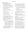
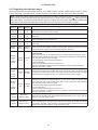
4-9 AIR-SENSOR adjustment
When the PWB assembly MAIN or the PWB assembly SENSOR is replaced, perform this adjustment after
completing reassembling the projector.
1. Open HIDDEN SERVICE MENU and choose AIR-SENSOR by using
button.
Service menu comes up by following operation.
By the control panel By the remote control transmitter
1. Display the Advanced menu by
the “MENU” button.
2. Select the “OPTION” on the
menu.
3. Continue press the button “ ”
fi rst, then press the button “ ”
together with “INPUT”, and hold
for 3 seconds.
1. Display the Advance menu by
the “MENU” button. (If EASY
MENU appears, choose “Go to
Advance menu” to display
ADVANCE MENU.)
2. Select the “OPTION” on the menu.
3. Press the “LIGHT” button.
Next hold the “LIGHT” button
for 3 seconds.
2. Press the button. Next press the [ ] button to select EXECUTE. The adjustment program runs auto-
matically.
3. After the massage of "END" is displayed, check the Offset value displayed according to the following spec
Spec. : 5 Offset: 65
4. If out of spec, confirm the below conditions Then retry the same adjustment.
Description
(a) Installing the air filter correctly.
(b)
No obstruction and dust on air filter. (If not good condition, clean or replace
the air filter.)
(c) Using the proper type of air filter.
(d) Installing the PWB assembly SENSOR correctly.
(e) Connecting the proper wires to E7A1 and E981 firmly.
(f) The component I7A2 on the PWB assembly MAIN stands vertically
(g) The component D981 on the PWB assembly SENSOR stands vertically
5. If the all conditions above is okay, replace the PWB assembly Main.
HIDDEN SERVICE
FILTER TIME ON
MUTE COLOR BLACK
AIR SENSOR
SOFT RESET
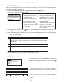
4-10 IRIS adjustment
Select “OPTION” in the FACTORY MENU, and press the
[ ] button to display the IRIS-A menu. Then press the [ ]
button to start the automatic adjustment.
This adjustment takes about 5 seconds. The image
becomes dark and bright while this period. When the
adjustment completes, the cursor moves to “OK”.
Note that the cursor moves to “NG” when adjustment
fails. Then make sure connection of EW01 to MAIN
board.
C.UNIF.
STRIPE
VID-AD
DAC-P
FACTORY MENU
GAMMA
OPTION
<C11H Soft Ver.>
PW:xxxx/yy/zz aa:bb:cc
IRIS-A >>EXE O: 51 C: 172
IRIS-A >>EXE NG O: 255 C: 255
IRIS-A >>EXE OK O: 51 C: 172

12
PJ-TX100(C11H)
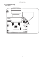
5. Troubleshooting
Check points
P601
P701
P501
1
14 15
28
IV03
EW01
E805
E802
E301
IV06
E7A1
E301
E801
E804
E806
D841(C)
S307
S301
(MENU)
S302
(INPUT)
E800
D301
(POWER)
D302
(TEMP)
D303
(LAMP)
112
PWB
assembly
REMC
TSW
PWB assembly MAIN

13
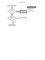
PJ-TX100(C11H)
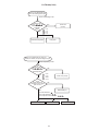
Power can not be turned on
Are
voltage input at
pins , , , of E800
on the PWB assembly Main
at standby mode?
: +12V
: +17V
: +6.6V
: +4.1V
Power unit (circuit)Lamp door SW
Fuse
on the Filter unit
Filter unit
Reset the Lamp door
NO
YES
Disconnect
TSW form Power unit
(circuit). And check
TSW short or
open?
PWB assembly Main
Short
YES
TSW
Open
Is the Lamp door
installed correctly?
NO
What is the state of
TEMP indicator D302?
Not light
Blinks
Jump to * on the page 14
1
1
3
5
7
3
57

14
PJ-TX100(C11H)
Lamp does not light
What is the
state of LAMP indicator
D303 during operation?
Power unit (ballast)
Lamp
PWB assembly Main
Power unit (ballast)
Light
PWB assembly Main
YES
Not light
NO
YES
Change the lamp.
Does lamp light?
Power unit (circuit)
Not light
Install the Lamp
Light NG
Is the LAMP
installation correct?
YES
NO
What is the state
of TEMP indicator D302?
Not light
Blinks
DC FAN
(Lamp)
H (3.3V)
"L" = 0V
L (OV)
1
Is the
voltage at the
of E804 on the PWB
assembly Main fixed to "L"
during warming-up?
"L" = 0V
Measure
sure voltage at the
cathode pin of D841 on
the PWB assembly
Main.
DC FAN
(Panel)
YES
(Normal)
Does the
signal at the pin
of E801 have a amplitude
of 3.3V and a frequency
of 40Hz or
more?
PWB assembly Main
Is the voltage
at the of E804 on
the PWB assembly Main
set to "L" during
warming-up?
3
1
C
DC FAN
(Sub)
NO
YES
(L=0V)
Is the
voltage at the pin
of E806 on the PWB
assembly Main set
to “L” ?
*
NO
(Fan lock)
1

15
PJ-TX100(C11H)
Picture is not displayed only
when the RGB signal is input
PWB assembly Main
LCD panel
Check at operating mode
Power unit
(circuit)
NO
YES
Are
voltage input
at pins , , , of
E800 on the PWB
assembly
Main?
1 35 7
1
3
5
7
: +12V
: +17V
:+6.6V
:+4.1V
Power unit (circuit)
NO
YES
YES
SM5301BS (IC)
NO
Are
voltage input at
pins , , , of
E800 on the PWB
assembly Main?
: +12V
: +17V
: +6.6V
: +4.1V
At Video selected :
At S-video selected : ,
At Component video selected : , ,
PWB assembly Main
LCD module assembly
TE 8200 PF (IC)
Check at operating mode
7
1
3
5
Picture is not displayed only when the
VIDEO, S-VIDEO, Component Signal is input
7
135
Is the
signal waveform
observed on the output
pins of IV03 ?
11 14
11 14
17
17

16
PJ-TX100(C11H)
The check after parts change
1. PC power supply OFF
2. Connection of cable
3. Projector starting
4. PC starting
*When not operating :
PC set up change of cable.
Can not control to RS-232C
PWB assembly Main
NO
YES
NO
YES
Use cross cable
Check the
RS-232C cable.
Are pin No. 2 and 3
crossed?
Power unit (circuit)
Check the
power supply voltage
of E800 the voltage
correct?
: +12V
: +17V
: +6.6V
: +4.1V
7
1
3
5

17
PJ-TX100(C11H)
6. Service points
6-1 Lead free solder [CAUTION]
This product uses lead free solder (unleaded) to help preserve the environment. Please read these
instructions before attempting any soldering work.
Lead free solder indicator
Printed circuit boards using lead free solder are engraved with an "F" or "LF".
Properties of lead free solder
The melting point of lead free solder is 40-50˚C higher than leaded solder.
Servicing solder
Solder with an alloy composition of Sn-3.0Ag-0.5Cu or Sn-0.7Cu is recommended.
Although servicing with leaded solder is possible, there are a few precautions that have to be taken. (Not
taking these precautions may cause the solder to not harden properly, and lead to consequent malfunctions.)
Precautions when using leaded solder
Remove all lead free solder from soldered joints when replacing components.
If leaded solder should be added to existing lead free joints, mix in the leaded solder thoroughly after the
lead free solder has been completely melted (do not apply the soldering iron without solder).
Servicing soldering iron
A soldering iron with a temperature setting capability (temperature control function) is recommended.
The melting point of lead free solder is higher than leaded solder. Use a soldering iron that maintains a high
stable temperature (large heat capacity), and that allows temperature adjustment according to the part being
serviced, to avoid poor servicing performance.
Recommended soldering iron:
Soldering iron with temperature control function (temperature range: 320-450˚C)
Recommended temperature range per part:
Part Soldering iron temperature
Mounting (chips) on mounted PCB 320˚C±30˚C
Mounting (chips) on empty PCB 380˚C±30˚C
Chassis, metallic shield, etc. 420˚C±30˚C
PWB assembly MAIN
PWB assembly SENSOR
PWB assembly REMC
POWER UNIT (BALLAST)
POWER UNIT (CIRCUIT)
FILTER UNIT
The PWB assembly which has used lead free solder
CAUTION
Always wear safety glasses to prevent fumes or molten solder from getting into the eyes. Lead free solder
can splatter at high temperatures (600˚C).

18
PJ-TX100(C11H)
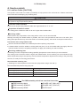
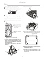
6-2 Cautions when removing the PWB assembly MAIN
When removing the PWB assembly MAIN, there is danger of damaging the connector connecting cables.
1) Disconnect 12 cables and remove 3 screws.
PWB assembly MAIN
3 screws
2) Remove 2 screws.
2 screws
3) Lift up the rearward of the PWB assembly MAIN to the front, while pushing rear portion of bottom case
toward the outside so that the terminals of MAIN board may not be caught in bottom case. And then dis-
connect cable.
6-3 Cautions When Removing The Power Unit (BALLAST)
When removing the cable (CNBAR) connected to Power Unit (BALLAST), there is danger of damaging the
small PWB connecting cables.
REAR
Disconnect the cable.
FRONT
Lift up
PWB assembly Main

19
PJ-TX100(C11H)
6-4 Before Replacing The LCD/Lens Prism
You should not replace separately the parts of the liquid crystal LCD/Lens prism because it works properly
only when used together. Therefore, regarding these parts, you can either replace part, LCD/Lens prism
assembly, or send the whole unit LCD/Lens prism assembly back to HITACHI, where we will replace the
malfunctioning part, recondition the device and send it back to you.
DISTRIBUTOR HITACHI
G Panel
Do not disassemble the unit
because replacement of separate
parts is not possible.
Return
Replacement of G Panel Reconditioning
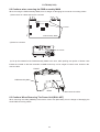
6-5 Cleaning up dust from panels and optical filters
1. Preparation
Please prepare cleaning tools and materials as follows. And prepare relatively clean room not to work in
additional dust, while removing operation.
(1) Swab for cleaning •••••• P#: NX08061, "Cotton stick L147"
(2) Air duster (Dust blower, spray can)
(3) Vacuum cleaner
2. Disassemble and open the maintenance hole.
(1) Turn off the projector, and unplug the power cord.
(2) Remove the top cover, according to the disassembling diagram of chapter 8.
(3) Remove the PWB assembly MAIN, according to the Chapter6-2.
(4) Remove the Intake LID.
(5) Re-assemble the PWB assembly MAIN, and re-connect toward projection lens.
Then place the board vertically shown above so that LCD panels can be seen.
Note that connectors for LCD panels should be empty.
Connect cables
Intake lid
Flexible cables of LCD panel
PWB assembly MAIN

20
PJ-TX100(C11H)
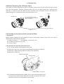
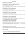
3. Maintenance point
Each color part has same
construction.
By using swab and air duster,
you can easily remove dust
from panel and optical filters.
4. Cleaning the panels and optical filters
(1) Turn on the set and lit on the lamp.
(2) Set blank screen to white.
(3) By using swab and air duster, remove the dust. Focusing dust makes you check the dust on screen.
(4) If cleaning up dust is hard, clean them again after powering off, disconnecting power cord and remov-
ing Intake upper.
• While removing the dust, separated dust will
be blown off by air cooling system.
• Please pay attention not to damage panel
and filters.
5. Re-assembly
(1) Turn off the set and remove the PWB assembly MAIN.
(2) Set the intake LID.
(3) Re-assemble the PWB assembly MAIN.
(4) Re-assemble the set.
(5)
While re-assembling, please clean the intake LID and intake filter and filter cover by using vacuum cleaner.
ᴾ
ᴾ
Panel
Swab
Holder
Optical filters
Separatied formationActua l formation
Swab
Panel
Optical filters
Holder
Air
Page is loading ...
Page is loading ...
Page is loading ...
Page is loading ...
Page is loading ...
Page is loading ...
Page is loading ...
Page is loading ...
Page is loading ...
Page is loading ...
Page is loading ...
Page is loading ...
Page is loading ...
Page is loading ...
Page is loading ...
Page is loading ...
Page is loading ...
Page is loading ...
Page is loading ...
Page is loading ...
Page is loading ...
Page is loading ...
Page is loading ...
Page is loading ...
Page is loading ...
Page is loading ...
Page is loading ...
Page is loading ...
Page is loading ...
Page is loading ...
Page is loading ...
Page is loading ...
Page is loading ...
Page is loading ...
Page is loading ...
Page is loading ...
Page is loading ...
Page is loading ...
Page is loading ...
Page is loading ...
Page is loading ...
Page is loading ...
Page is loading ...
Page is loading ...
Page is loading ...
-
 1
1
-
 2
2
-
 3
3
-
 4
4
-
 5
5
-
 6
6
-
 7
7
-
 8
8
-
 9
9
-
 10
10
-
 11
11
-
 12
12
-
 13
13
-
 14
14
-
 15
15
-
 16
16
-
 17
17
-
 18
18
-
 19
19
-
 20
20
-
 21
21
-
 22
22
-
 23
23
-
 24
24
-
 25
25
-
 26
26
-
 27
27
-
 28
28
-
 29
29
-
 30
30
-
 31
31
-
 32
32
-
 33
33
-
 34
34
-
 35
35
-
 36
36
-
 37
37
-
 38
38
-
 39
39
-
 40
40
-
 41
41
-
 42
42
-
 43
43
-
 44
44
-
 45
45
-
 46
46
-
 47
47
-
 48
48
-
 49
49
-
 50
50
-
 51
51
-
 52
52
-
 53
53
-
 54
54
-
 55
55
-
 56
56
-
 57
57
-
 58
58
-
 59
59
-
 60
60
-
 61
61
-
 62
62
-
 63
63
-
 64
64
-
 65
65


Ask a question and I''ll find the answer in the document
Finding information in a document is now easier with AI
Related papers
-
Hitachi CP-X265 User manual
-
Hitachi PJ-TX100E User manual
-
-
-
Hitachi X253 - CP XGA LCD Projector User manual
-
-
-
-
-
Other documents
-
FSR PWB-320-Tr Owner's manual
-
-
 ActronControls LE75 Operating instructions
-
Nikon Nikon 1 J1 Reference guide
-
Hager tebis TX100 Operating instructions
-
Pioneer VREC-200CH Installation guide
-
Sunnydaze Decor DSL-698 Installation guide
-
Eiki LC-XB41 User manual
-
-
Freedom9 freeView XL C11H User manual
