Kenwood TK-780 User manual
- Category
- Two-way radios
- Type
- User manual
This manual is also suitable for

© B62-1438-10 (E)
09 08 07 06 05 04 03 02 01
KENWOOD CORPORATION
TK-780/ TK-880
GEBRUIKSAANWIJZING
BEDIENUNGSANLEITUNG
MANUAL DE INSTRUCCIONES
MODE D’EMPLOI
INSTRUCTION MANUAL
VHF FM TRANSCEIVER/ UHF FM TRANSCEIVER
ÉMETTEUR-RÉCEPTEUR FM VHF/ ÉMETTEUR-RÉCEPTEUR FM UHF
TRANSCEPTOR FM VHF/ TRANSCEPTOR FM UHF
VHF-FM-TRANSCEIVER/ UHF-FM-TRANSCEIVER
VHF FM ZENDONTVANGER/ UHF FM ZENDONTVANGER
RICETRASMETTITORE FM VHF/ RICETRASMETTITORE FM UHF
MANUALE DI ISTRUZIONI

VHF FM TRANSCEIVER/
UHF FM TRANSCEIVER
INSTRUCTION MANUAL
KENWOOD CORPORATION
TK-780/ TK-880

i
THANK YOU!
We are grateful you chose KENWOOD for your personal mobile applications.
We believe this easy-to-use transceiver will provide dependable communications
to keep personnel operating at peak efficiency.
KENWOOD transceivers incorporate the latest in advanced technology. As a
result, we feel strongly that you will be pleased with the quality and features of
this product.
MODELS COVERED BY THIS MANUAL
• TK-780: VHF FM Transceiver
• TK-880: UHF FM Transceiver
PRECAUTIONS
Please observe the following precautions to prevent fire, personal injury, and
transceiver damage.
• Do not attempt to configure the transceiver while driving; it is too dangerous.
• Do not modify the transceiver for any reason.
• Do not expose the transceiver to long periods of direct sunlight, nor place it near
heating appliances.
• Do not place the transceiver in excessively dusty, humid, or wet areas, nor on
unstable surfaces.
• If an abnormal odour or smoke is detected coming from the transceiver, turn OFF the
power immediately. Contact your KENWOOD dealer.
NOTICES TO THE USER
◆
GOVERNMENT LAW PROHIBITS THE OPERATION OF UNLICENSED RADIO
TRANSMITTERS WITHIN THE TERRITORIES UNDER GOVERNMENT CONTROL.
◆
ILLEGAL OPERATION IS PUNISHABLE BY FINE AND/OR IMPRISONMENT.
◆
REFER SERVICE TO QUALIFIED TECHNICIANS ONLY.
SAFETY: It is important that the operator is aware of, and understands, hazards
common to the operation of any transceiver.
WARNING!
◆
EXPLOSIVE ATMOSPHERES (GASES, DUST, FUMES, etc.)
Turn OFF your transceiver while taking on fuel or while parked in a gasoline service station. Do
not carry spare fuel containers in the trunk of your vehicle if your transceiver is mounted in the
trunk area.
◆
INJURY FROM RADIO FREQUENCY TRANSMISSIONS
Do not operate your transceiver when somebody is either touching the antenna or standing within
two to three feet of it, to avoid the possibility of radio frequency burns or related physical injury.
◆
DYNAMITE BLASTING CAPS
Operating the transceiver within 500 feet of dynamite blasting caps may cause them to explode.
Turn OFF your transceiver when in an area where blasting is in progress, or where “TURN OFF
TWO-WAY RADIO” signs have been posted. If you are transporting blasting caps in your vehicle,
make sure they are carried in a closed metal box with a padded interior. Do not transmit while
the caps are being placed into or removed from the container.

ii
CONTENTS
UNPACKING AND CHECKING EQUIPMENT............................................ 1
SUPPLIED ACCESSORIES .................................................................. 1
PREPARATION ........................................................................................... 2
TOOLS REQUIRED ............................................................................... 2
POWER CABLE CONNECTION ........................................................... 2
INSTALLING THE TRANSCEIVER ....................................................... 3
ORIENTATION ............................................................................................. 4
FRONT PANEL ...................................................................................... 4
DISPLAY ................................................................................................ 5
REAR PANEL ........................................................................................ 5
PROGRAMMABLE AUXILIARY FUNCTIONS ........................................... 6
BASIC OPERATIONS ................................................................................. 8
OPERATION OVERVIEW ...................................................................... 8
SWITCHING POWER ON/ OFF ............................................................ 8
ADJUSTING THE VOLUME .................................................................. 8
SELECTING A GROUP/ CHANNEL ..................................................... 8
MAKING A CALL ................................................................................... 8
RECEIVING A CALL.............................................................................. 8
TIME-OUT TIMER (TOT) ....................................................................... 9
HORN ALERT ........................................................................................ 9
ADVANCED OPERATIONS ...................................................................... 10
SCAN ................................................................................................... 10
Priority Scan .................................................................................. 10
5-TONE SIGNALLING ......................................................................... 10
DMS: ALPHANUMERIC 2-WAY PAGING FUNCTION ........................... 11
KEY FUNCTIONS ................................................................................ 11
SELCALL (SELECTIVE CALLING) .................................................... 12
Transmitting .................................................................................. 12
Receiving ....................................................................................... 12
Identification Codes ..................................................................... 12
STATUS MESSAGE ............................................................................ 13
Transmitting .................................................................................. 13
Receiving ....................................................................................... 13
Reviewing Messages in the Queue Memory .............................. 14
Automatic Status Response ........................................................ 14
SHORT MESSAGES FEATURE ......................................................... 14
GPS REPORT ...................................................................................... 14
DTMF (DUAL TONE MULTI FREQUENCY) CALLS ................................ 15
MAKING A DTMF CALL ...................................................................... 15
DTMF SIGNALLING ............................................................................ 15
STUN .................................................................................................... 15
AUDIBLE USER FEEDBACK TONES ..................................................... 16

1
UNPACKING AND CHECKING EQUIPMENT
Note:
The following unpacking instructions are for use by your
KENWOOD
dealer, an authorized
KENWOOD
service facility, or the factory.
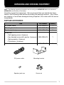
Carefully unpack the transceiver. We recommend that you identify the items
listed in the following table before discarding the packing material. If any items
are missing or have been damaged during shipment, file a claim with the carrier
immediately.
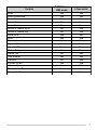
SUPPLIED ACCESSORIES
DC power cable Mounting bracket
Screw setSpeaker jack cap
metI rebmuNtraP ytitnauQ
elbacrewopCDXX-8343-03E1
tekcarbgnitnuoMXX-7260-92J1
packcajrekaepSXX-5320-90B1
:teswercS
XX-5930-99N1
)seceip4(wercsgnippat-fleS•
)seceip4(rehsawhtiwwercsdedaeh-xeH•
)seceip4(rehsawgnirpS•
)seceip4(rehsawtalF•
launamnoitcurtsnIXX-8341-26B1

2
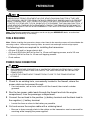
VARIOUS ELECTRONIC EQUIPMENT IN YOUR VEHICLE MAY MALFUNCTION IF THEY ARE
NOT PROPERLY PROTECTED FROM THE RADIO FREQUENCY ENERGY WHICH IS PRESENT
WHILE TRANSMITTING. ELECTRONIC FUEL INJECTION, ANTI-SKID BRAKING, AND CRUISE
CONTROL SYSTEMS ARE TYPICAL EXAMPLES OF EQUIPMENT THAT MAY MALFUNCTION. IF
YOUR VEHICLE CONTAINS SUCH EQUIPMENT, CONSULT THE DEALER FOR THE MAKE OF
VEHICLE AND ENLIST HIS AID IN DETERMINING IF THEY WILL PERFORM NORMALLY WHILE
TRANSMITTING.
Note
: The following preparation instructions are for use by your
KENWOOD
dealer, an authorized
KENWOOD
service facility, or the factory.
TOOLS REQUIRED
Note
: Before installing the transceiver, always check how far the mounting screws will extend below the
mounting surface. When drilling mounting holes, be careful not to damage vehicle wiring or parts.
The following tools are required for installing the transceiver:
•A 6 mm (1/4 inch) or larger electric drill.
•A 4.2 mm (5/32 inch) drill bit for the 5 x 16 mm self-tapping screws, and a 3.2 mm
(1/8 inch) drill bit for the 4 x 16 mm self-tapping screws.
• Circle cutters.
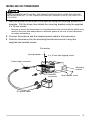
POWER CABLE CONNECTION
◆
THE TRANSCEIVER OPERATES IN 12 V NEGATIVE GROUND SYSTEMS ONLY! CHECK
THE BATTERY POLARITY AND VOLTAGE OF THE VEHICLE BEFORE INSTALLING THE
TRANSCEIVER.
◆
LOCATE THE POWER INPUT CONNECTOR AS CLOSE TO THE TRANSCEIVER AS
POSSIBLE.
1 Check for an existing hole, conveniently located in the firewall, where the
power cable can be passed through.
• If no hole exists, use a circle cutter to drill the firewall, then install a rubber
grommet.
2 Run the two power cable leads through the firewall and into the engine
compartment, from the passenger compartment.
3 Connect the red lead to the positive (+) battery terminal and the black lead to
the negative (–) battery terminal.
• Locate the fuse as close to the battery as possible.
4 Coil and secure the surplus cable with a retaining band.
• Be sure to leave enough slack in the cables so the transceiver can be removed for
servicing while keeping the power applied.
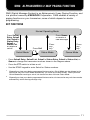
PREPARATION

3
Hex-headed screw
DC power cable
Mounting
bracket
5 x 16 mm self-tapping screw
Spring washer
Flat washer
Antenna
connector
Power input connector
FOR PASSENGER SAFETY, INSTALL THE TRANSCEIVER SECURELY, USING THE SUPPLIED
MOUNTING BRACKET, SO THE TRANSCEIVER WILL NOT BREAK LOOSE IN THE EVENT OF A
COLLISION.
1 Mark the position of the holes in the dash by using the mounting bracket as a
template. Drill the holes, then attach the mounting bracket using the supplied
5 x 16 mm screws.
• Be sure to mount the transceiver in a location where the controls will be within easy
reach of the user and where there is sufficient space at the rear of the transceiver
for cable connections.
2 Connect the antenna and the supplied power cable to the transceiver.
3 Slide the transceiver into the mounting bracket and secure it using the
supplied hex-headed screws.
INSTALLING THE TRANSCEIVER

4
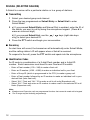
ORIENTATION
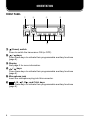
FRONT PANEL
qq
qq
q (Power) switch
Press to switch the transceiver ON (or OFF).
ww
ww
w / keys
Press these keys to activate their programmable auxiliary functions
{page 6}.
ee
ee
e Display
See page 5 for more information.
rr
rr
r / keys
Press these keys to activate their programmable auxiliary functions
{page 6}.
tt
tt
t Microphone jack
Insert the microphone plug into this connector.
yy
yy
y , A, B, C, D , and CALL keys
Press these keys to activate their programmable auxiliary functions
{page 6}.
q
ty
we r

5
rotacidnI noitpircseD
suoiravsallewsasrebmunlennahcdnapuorgehtsyalpsiD
.snoitcnufelbammargorprelaed
.lennahcytiroirpasilennahcdetcelesehtnehwsraeppA
sademmargorpyeksserpuoynehwsraeppA rotinoM .
.reviecsnartsihtnodesutonsinocisihT
.edomnacSnierauoyelihwsraeppA
.noitcnufyrailixuaehtetavitcauoynehwsraeppA
.reviecsnartsihtnodesutonsinocisihT
.yromemeueuqehtniderotssiegassemanehwsraeppA
.egassemwenaevieceruoynehwsehsalF
ruoyhcihw(emanrorebmunlennahcdnapuorgehtsyalpsiD
sallewsa)sretcarahc01otpuhtiwmargorpnacrelaed
siyalpsidtsomtfelehT.SMDgnisunehwsegassemdeviecer
(rotacidniddanasadesu ▼ siyalpsidtsomthgirehtdna)
(relbmarcSdna)(llaCevitceleSrofdesu _ ddaehT.)
ehtfotuodekcoltoneratahtslennahcehtswohsrotacidni
relaederarelbmarcSdnallaCevitceleS.ecneuqesgninnacs
.snoitcnuflanoitpoelbammargorp
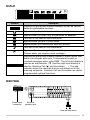
DISPLAY
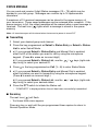
REAR PANEL
External
speaker jack
Power input
connector
Antenna connector

6
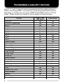
PROGRAMMABLE AUXILIARY FUNCTIONS
Keys w, r, and y {page 4} can be programmed with the auxiliary functions
listed in the following table. The keys can only be programmed with functions,
depending on whether you are using a DTMF/2-Tone/DMS model or a 5-Tone
model. Please contact your dealer for further details on these functions.
noitcnuF
/enoT-2/FMTD
ledomSMD
ledomenoT-5
laiDotuAseYseY
gnimmargorPlaidotuAseYoN
AXUAseYseY
BXUAseYseY
1llaCoNseY
2llaCoNseY
3llaCoNseY
4llaCoNseY
5llaCoNseY
6llaCoNseY
nwoDlennahCseYseY
yrtnElennahCseYseY
emaNlennahCseYseY
pUlennahCseYseY
llaCycnegremEseYseY
emuloVdexiFseYseY
nwoDpuorGseYseY
pUpuorGseYseY
lennahCemoHseYseY
trelAnroHseYseY
kcoLyeKseYseY
rotinoMseYseY
yratnemoMrotinoMseYseY
enoNseYseY
enoTleSrotarepOseYseY
sserddAcilbuPseYseY
eueuQseYseY
drowssaPoidaRseYseY
yrtnEevieceRoNseY

7
noitcnuF
/enoT-2/FMTD
ledomSMD
ledomenoT-5
nacSseYseY
ddA/eteleDnacSseYseY
relbmarcSseYseY
yrtnEllacleSoNseY
tsiLllacleSoNseY
yrtnEsutatS+llacleSoNseY
tsiLsutatS+llacleSoNseY
SPGdneSseYoN
tfihSseYseY
leveLhcleuqSseYseY
yratnemoMhcleuqSseYseY
ffOhcleuqSseYseY
yrtnEsutatSoNseY
tsiLsutatSoNseY
dnuorAklaTseYseY
refsnarToNseY
nwoDemuloVseYseY
pUemuloVseYseY
nwoD/pUlennahCseYseY
nwoD/pUpuorGseYseY

8
BASIC OPERATIONS
OPERATION OVERVIEW
Your dealer can program your transceiver for DTMF/2-Tone/DMS signalling or
5-Tone signalling.
This transceiver can handle up to 250 groups with 250 channels in each group.
Groups, channels, and their functions are programmed by your dealer.
SWITCHING POWER ON/ OFF
Press the switch to switch the transceiver ON (or OFF).
ADJUSTING THE VOLUME
Press the keys programmed as Volume Up and Volume Down to adjust the
volume. Volume Up increases the volume; Volume Down decreases it.
SELECTING A GROUP/ CHANNEL
Select the desired group and channel using the keys programmed with the
Group and Channel functions.
MAKING A CALL
Note:
If the selected channel is programmed with QT (Quiet Talk) or DQT (Digital Quiet Talk), remove
the microphone from the microphone hanger to disable QT or DQT, then listen to the channel to make
sure nobody is talking on it. If the selected channel is not programmed with QT or DQT, simply listen to
the channel to make sure nobody is talking on it; in this case, you need not remove the microphone from
its hanger.
1 Select your desired group and channel.
• If the channel is busy, wait until it becomes free.
2 Press and hold the PTT switch, then speak into the microphone. Release the
PTT switch to receive.
• For best sound quality at the receiving station, hold the microphone approximately
3 ~ 4 cm (1.5 inches) from your mouth.
3 When your conversation is finished, return the microphone to its hanger.
RECEIVING A CALL
1 Select your desired group and channel. (If the Scan function has been
programmed, you can switch it ON or OFF as desired.)
2 When you hear the dispatcher’s voice, readjust the volume as necessary.

9
TIME-OUT TIMER (TOT)
The purpose of the Time-out Timer is to prevent any caller from using a channel
for an extended period of time.
If you continuously transmit for a period of time that exceeds the programmed
time, the transceiver will stop transmitting and an alert tone will sound. To stop
the tone, release the PTT switch.
Your dealer can program the TOT time in the range of 30 seconds to 5 minutes.
HORN ALERT
If Horn Alert has been activated by your dealer, your vehicle horn or some other
type of external alert, will sound when certain calls are received. This is a useful
function when you are away from your vehicle.

10
ADVANCED OPERATIONS
SCAN
If the Scan function is programmed, groups or channels can be scanned by
pressing the key programmed as Scan. When the Scan key is pressed, the
SCN indicator and “-SCAN-” or the revert group/ channel number appear on the
display. Scanning starts.
Scan can be used as either Single Scan or Multi Scan. Single Scan monitors
only the channels of a single group. Multi Scan monitors all channels of every
group.
When a call is received, scanning stops and the group and channel digits
appear. Press the PTT switch and speak into the microphone to respond to the
call. The transceiver will continue scanning after an adjustable time delay if the
PTT switch is released and no further signal is received.
When the displayed group is not locked out of the scanning sequence, the add
indicator ( ▼ ) will appear on the display.
■ Priority Scan
The priority channel must be programmed in order for Priority Scan to
function.
The transceiver will automatically change to the priority channel when a signal
is received on it, even if a signal is being received on a normal channel.
The indicator appears when the displayed channel is the priority channel.
5-TONE SIGNALLING
5-Tone Signalling is either activated or deactivated by your dealer.
5-Tone Signalling only opens the squelch when the transceiver receives five
tones corresponding to those set up in your transceiver. When the squelch
opens, you will be able to hear the caller without any further action.
After a correct 5-Tone signal is received and the squelch opens, pressing the key
programmed as Monitor will cancel the connection.
If your dealer programmed Transpond for 5-Tone Signalling, your transceiver will
automatically send an acknowledgment signal to stations that called you with the
correct signal.
If your dealer programmed Tone Alert for 5-Tone Signalling, your transceiver will
emit a beep when the correct signal is received.
Note:
This transceiver is also capable of decoding 2-Tone signals.

11
DMS: ALPHANUMERIC 2-WAY PAGING FUNCTION
DMS (Digital Message System) is an Alphanumeric 2-way Paging Function, and
is a protocol owned by KENWOOD Corporation. DMS enables a variety of
paging functions on your transceiver, some of which depend on dealer
programming.
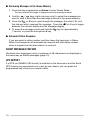
KEY FUNCTIONS
• Press Selcall Entry, Selcall List, Selcall + Status Entry, Selcall + Status List, or
Queue to change the transceiver mode as shown in the diagram above.
• Press the PTT switch to initiate a call.
• Use the DTMF keypad to enter Selcall or Status numbers.
1
Depending on how your dealer programmed the transceiver, Selcall Mode may be skipped or the
transceiver may exit Selcall Mode automatically (as shown by the dash arrow). When you enter
Selcall Mode after receiving a selcall, the transceiver does not enter Status Mode.
2
Depending on how your dealer programmed the transceiver, the transceiver may exit these modes
automatically, rather than by pressing a key.
Selcall Mode
Queue Mode
Status Mode
Normal Operating Mode
Press Selcall
Entry, Selcall
List, Selcall +
Status Entry,
Selcall +
Status List,
or receive a
selcall
Press Queue
or receive a
new message
Press
any
key
Press
any
key
Press Call
or
1
2
2

12
SELCALL (SELECTIVE CALLING)
A Selcall is a voice call to a particular station or to a group of stations.
■ Transmitting
1 Select your desired group and channel.
2 Press the key programmed as Selcall Entry or Selcall List to enter
Selcall Mode.
3 a) If you pressed Selcall Entry and Manual Dial is enabled, enter the ID of
the station you want to call by using the microphone keypad. (Press # to
erase an incorrect digit.)
b) If you pressed Selcall List, use the / keys (right side keys
only) to select your desired ID.
4 Press the PTT switch and begin your conversation.
■ Receiving
An alert tone will sound, the transceiver will automatically enter Selcall Mode,
and the calling station’s ID will appear when a Selcall is received.
To respond to the call, press the PTT switch and speak into the microphone.
■ Identification Codes
An ID code is a combination of a 3-digit Fleet number and a 4-digit ID
number. Each transceiver must have its own Fleet and ID number.
• Enter a Fleet number (100 ~ 349) to make a fleet call.
• Enter an ID number (1000 ~ 4999) to make an individual call in your fleet.
• Enter a Group ID (which is programmed in the FPU) to make a group call.
• Enter a Fleet number followed by an ID number to make an individual call in your
desired fleet (Inter-fleet call).
• Select “ALL” Fleet and “ALL” ID to make a call to all units (Broadcast call).
• Select “ALL” Fleet and enter an ID number to make a call to the selected ID in all
fleets (Supervisor call).
Note:
◆
Broadcast and Supervisor calls are programmed functions that cannot be made with a keypad.
◆
The ID range may be limited by programming.

13
STATUS MESSAGE
You can send and receive 2-digit Status messages (10 ~ 79) which may be
decided in your talk group. Messages can contain up to 16 alphanumeric
characters.
A maximum of 15 received messages can be stored in the queue memory of
your transceiver. These saved messages can be reviewed after reception. If the
queue memory is full, the oldest message will be erased when a new message is
received. The mail icon ( ) lights when a message is stored in the queue
memory.
Note:
All stored messages will be cleared when the transceiver power is turned OFF.
■ Transmitting
1 Select your desired group and channel.
2 Press the key programmed as Selcall + Status Entry or Selcall + Status
List to enter Selcall Mode.
3 a) If you pressed Selcall + Status Entry and Manual Dial is enabled,
enter the ID of the station you want to call by using the microphone
keypad. (Press # to erase an incorrect digit.)
b) If you pressed Selcall + Status List, use the / keys (right side
keys only) to select your desired ID.
4 Press or the key programmed as Call (1 ~ 6) to enter Status Mode.
5 a) If you pressed Selcall + Status Entry and Manual Dial is enabled,
enter the status you want to transmit by using the microphone keypad.
(Press # to erase an incorrect digit.)
b) If you pressed Selcall + Status List, use the / keys (right side
keys only) to select your desired status.
6 Press the PTT switch to initiate the Status call.
• “COMPLETE” is displayed when the call has been successfully transmitted.
■ Receiving
The mail icon ( ) will flash.
• The Queue Mode status appears.
Press any key or wait until the pre-programmed timer expires to return to
Normal Operation Mode.

14
■ Reviewing Messages in the Queue Memory
1 Press the key programmed as Queue to enter Queue Mode.
• The last received message is displayed with the message number.
2 Use the / keys (right side keys only) to select the message you
want to view, if more than one message is stored in the queue memory.
3 Press the D or 6 key to cycle through the message, the caller’s ID, and
the channel which received the message. Press the C or 4 key to toggle
between the numeric display and the message display.
4 To erase the message, press and hold the D key for approximately
1 second, or press the microphone # key.
■ Automatic Status Response
If you pre-select a status number and then leave the transceier in Status
Mode, the transceiver will automatically respond with that status number
when a request from the base station is received.
SHORT MESSAGES FEATURE
Received short messages (up to a maximum of 48 characters) are displayed in
the same way as Status messages {page 13}.
GPS REPORT
If a GPS unit (NMEA-0183 format) is installed on the transceiver and the Send
GPS function is programmed onto a key by your dealer, you can press the
programmed key to send your location data.

15
DTMF (DUAL TONE MULTI FREQUENCY) CALLS
MAKING A DTMF CALL
Note:
To make a DTMF call, you must have an optional microphone with a DTMF keypad. Ask your
dealer for more information.
There are two methods of making DTMF calls:
Manual dialing:
1 Press and hold the PTT switch.
2 Enter the desired digits using the microphone keypad.
• The corresponding DTMF tones sound each time you press a key.
• If you release the PTT switch, transmit mode will end, even if the complete number
has not been sent.
Store and sending:
1 Enter the desired digits using the microphone keypad.
• The digits appear on the display as you enter them.
2 After entering the complete number, press the key.
• The DTMF code is transmitted after pressing the key.
Note:
◆
You can only store up to 16 digits before sending. Entering more than 16 digits will cause an error
tone to sound.
◆
If you switch the power OFF before sending the number, the number will be cleared from memory.
DTMF SIGNALLING
Your dealer can program a group with a DTMF signalling code. When you
receive a call with a code that matches yours, the signalling indicator will flash
and a tone will sound. Squelch opens and you will hear the call.
Squelch will close when you receive a call with a code that matches your
signalling reset code.
When making a call on a group programmed with a DTMF signalling code, the
signalling indicator will light and the squelch will open.
STUN
Depending on how your dealer programs your transceiver, when you receive a
call containing a Stun code, either your transceiver will be disabled temporarily or
permanently. When disabled temporarily, a tone will sound and “LOCK 2” will
appear on the display. When disabled permanently, a tone will sound and
“ERROR” will appear on the display.
Temporarily disabled transceivers are re-enabled when you receive a call with a
Stun cancel code.

16
AUDIBLE USER FEEDBACK TONES
The transceiver emits various tones to indicate the transceiver’s operating status.
Contact your dealer for further information on these tones:
• Alert
• DMS Signalling Decode Alert Tone
• Group Call
• Individual Call
• Key Input Error
• Key Press [A]
• Key Press [B]
• Key Press [C]
• Power On
• Pre Alert
• Programmable Alert Tone
• Roll Over
•Transpond
•Warning
-
 1
1
-
 2
2
-
 3
3
-
 4
4
-
 5
5
-
 6
6
-
 7
7
-
 8
8
-
 9
9
-
 10
10
-
 11
11
-
 12
12
-
 13
13
-
 14
14
-
 15
15
-
 16
16
-
 17
17
-
 18
18
-
 19
19
-
 20
20


Kenwood TK-780 User manual
- Category
- Two-way radios
- Type
- User manual
- This manual is also suitable for
Ask a question and I''ll find the answer in the document
Finding information in a document is now easier with AI
Related papers
Other documents
-
GME TX4800 User manual
-
 GME Electrophone TX4200 Series User manual
-
Muratec IC-F50 User manual
-
Uniden UH015sx User manual
-
-
ICOM VE-PG4 Operating instructions
-
Vertex VX-1700 Operating instructions
-
Ritron NT-470-CANADA User manual
-
-
