Page is loading ...

DOC P/N 5001101A KIT P/N 5001100A Printed in USA Webasto Product N.A., Inc.
BlueHeat Coolant Heater
Thermo Top
Legend
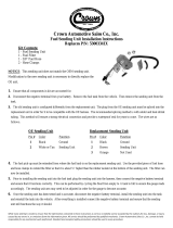
1BlueHeat Coolant Heater, Exhaust Tube, and Combustion Air Intake Silencer
2 Fuse Holder, Relays and Resistor Assembly
3Timer Control
4Fuel Pump
Special Tools
– Hose Clamping pliers
– Torque Wrench
Table of Contents
4
23
1
VW Passat
2.0L, 4CYL- FSI, Gasoline
Beginning Model Year: 2006
Special instructions for these models
Part locations may differ slightly dependent on
the vehicle model.
Be sure to check WWW.techwebasto.com for
the latest addition of this manual.
Foreword
Parts List 3
Vehicle Information 3
Scope and Purpose 3
Symbol Identification 4
General References 5
Preparation 5
Heater Installation Site 5
Installation
Electrical - Overview 6
Electrical Harness Installation 7
Timer Installation 8
Integration into the Blower System - Climatic 9
Integration into the Blower System - Climatronic 11
Heater Preparation/Installation 13
Air Intake tube Installation 14
Exhaust Installation 15
Integration into the Coolant System 16
Integration into the Fuel System 19
Blower Control Settings - Climatronic 23
Blower Control Settings - Climatic 23
Final Inspection, Initial Start-up and Concluding
Work 24
Heater Lockout Reset Procedure 25

– Improper installation or repair of Webasto heating and cooling systems can cause
fire or the leakage of deadly carbon monoxide leading to serious injury or death.
– Installation and repair of Webasto heating and cooling systems requires special
Webasto training, technical information, special tools and special equipment.
– NEVER attempt to install or repair a Webasto heating or cooling system unless you
have successfully completed the factory training course and have the technical skills,
technical information, tools and equipment required to properly complete the
necessary procedures.
– ALWAYS carefully follow Webasto installation and repair instructions and heed all
WARNINGS.
– Webasto rejects any liability for problems and damage caused by the system being
installed by untrained personnel.

3
VW Passat
Parts List
Vehicle Information
Foreword
This installation requires special expertise from a Webasto training course to install a Webasto Thermo Top
heater, which means that it may only be installed by a specially trained workshop or dealership. Webasto
cannot accept any liability for faults and damage caused by the system being installed by untrained personnel.
Scope and Purpose
These installation instructions are intended to support authorized Webasto trained distributors, dealers and
personnel in the installation of the Thermo Top (BlueHeat) Coolant Heaters.
These installation instructions apply to the vehicles listed on the front cover of this installation
document unless technical modifications on the vehicle influence the installation, excluding all liability claims.
Depending on the version and equipment in the vehicle, changes may be required to the installation work set
out in these installation instructions. In any event, the directives in the “installation manual” and “operating
manual” must be followed.
ATTENTION
All relevant state and provincial licensing regulations if any, governing the installation and use of auxiliary
heating devices must be observed!
CAUTION
Location of heater, installation of coolant lines, fuel system and components, wiring and control devices
are important for proper operation. Failure to comply with the installation instructions provided may result
in poor operation or damage to heater and vehicle components.
Quantity Part Part Number
1 Installation Kit For Vehicles With Automatic
Temperature Controls (Climatronic)
9013645A
1 Installation Kit For Vehicles With Manual
Temperature Controls (Climatic)
5001100A
Manufacturer Model Year Engine Type
Volkswagen Passat Beginning 2006 2.0L, 4CYL FSI

4
BlueHeat
TM
VW Passat
Symbol Identification
Symbols that define sections in manual
Mechanical Preparation
Electrical
Coolant
General Symbol Descriptions
Warning
Caution
Fuel
Exhaust
Combustion Air Intake
Refer to Webasto or Manufacturer Manual
Attention

VW Passat
5
General References
– Bare body parts, for example around drilled holes, must be treated with anti-corrosive coating.
– Secure hoses, cables and wiring harnesses with cable ties and fit protective hoses around them at chafing
points.
– Fit edge protectors (opened fuel hose) to sharp edges.
Preparation
Heater Kit
– Verify and identify all contents of kit.
Vehicle
– Open fuel cap and vent tank
– Release radiator pressure
– Remove battery and battery tray
– Remove air filter assembly and hoses
– Remove front left wheel well splashshield
– Remove left front fog lamp or trim panel
– Remove underbody splash shields
– Remove rear seat bottom
– Remove driver’s side floor trim
– Remove driver’s side dash trim panel
CAUTION
For reasons of safety due to possible fuel spillage, it is recommended that there be no more than 1/2 tank of fuel
present. If fuel quantity is greater than 1/2 of capacity, make provisions to reduce quantity of fuel.
– Protect vehicle fenders, panels and interior with covers
Heater Installation Site
ATTENTION
The Webasto Auxiliary Coolant Heater is installed on
the left side of the vehicle behind the front bumper.
Front bumper cover was removed for photographic
purposes only.
– (1) Webasto Auxiliary Coolant Heater (Installed)
1
Fig. 1
BlueHeat
TM

6
VW Passat
Electrical - Overview
ATTENTION
If not described differently, securing of wiring and cables is done with cable ties to the vehicle’s own wires and
cable harnesses.
ATTENTION
Timer control location is a recommendation only. Please consult with the customer before mounting.
2
1
br
rt sw
rtbr
+
-
bl
Fuel Line and Fuel
Pump Harness
1
2
1
2
12
Relay and Fuse Holder
– (1) Vehicle underhood fuse/relay center
– (2) Heater relay, fuses and mounting bracket
Fuel Pump Mounting Location
– (1) Webasto fuel pump
– (2) Vehicle fuel tank
Bulkhead Pass-through
– (1) Bulkhead opening
– (2) Timer Harness
Interior Fuse/Relay Center
– (1) Webasto blower integration point
– (2) Interior fuse/relay center

VW Passat
7
Electrical Harness Installation
ATTENTION
The two holes in the top of the relay/fuse mounting
bracket need to be enlarged to a accommodate two
existing vehicle screws.
Using a 21/64 drill bit enlarge the two holes in the top of
the relay/fuse mounting bracket.
– (1) Relay/fuse mounting bracket
– (2) 21/64 hole
Secure Webasto fuse holder and relay to mounting
bracket as shown in Figure 3.
– (1) Relay/fuse mounting bracket
– (2) Fuse holder
– (3) Relay
Remove hood stop and adjacent vehicle screw.
Position electrical mounting bracket where shown in
Figure 4 and re-install hood stop and existing screw.
– (1) Hood stop
– (2) Existing vehicle screw
– (3) Electrical mounting bracket
Webasto Power wire Connection
Secure webasto power wire to the vehicle power strip
located on the underhood fuse/relay center.
– (1) Fuse/relay power strip
– (2) Webasto power wire (+12V)
Fig. 2
12
Fig. 3
1
32
Fig. 4
3
1
2
Fig. 5
1
2

8
VW Passat
Webasto Harness Ground Wire Connection
Secure the webasto harness ground wire to an existing
vehicle ground located below the front headlight.
– (1) Existing vehicle ground location
– (2) Below front headlight
– (3) Webasto harness ground wire
Timer Harness Routing
Route the timer harness from the engine compartment to
the interior of the vehicle through the bulkhead grommet
next to the brake booster.
– (1) Brake booster
– (2) Bulkhead grommet location
– (3) Timer harness
Timer Installation
CAUTION
Check behind panels for obstructions before drilling
holes.
ATTENTION
Before installing the timer, please confirm the
installation location with the customer.
Affix supplied template to panel. Drill 10 mm (25/64 in.)
and 2.5 mm (3/32 in.) holes where indicated on template.
Figure 6 shows a translated sample of the template
supplied.
ATTENTION
Before installing the timer, please confirm the
installation location with the customer.
– (1) Timer
Fig. 6
1
3
2
Fig. 7
12
3
Fig. 8
Fig. 9
Example of Timer Mounting

VW Passat
9
Integration into the Blower System With Man-
ual Temp. Controls - Climatic
Loosen vehicle interior fuse center.
Disengage contact (3).
Remove black/red wire (2) from fuse block.
– (1) Interior fuse/relay center
– (2) Black/Red wire
– (3) Contact
ATTENTION
Make connections as shown in wiring schematic (fig.
12).
– (1) Black wire from K3 relay pin 30
– (2) Red wire from relay K3 pin 87 to vehicle SC40
– (3) Connector
– (3) Black/Red wire from fuse panel
Fig. 10
1
3
2
Fig. 11
1
2
4
3

10
VW Passat
TABLE 1. Climatic Control System
Webasto Heater Comp. Vehicle Components Wire Colors
HG = Webasto Heater SC40 = Blower Fuse rd = red
F3 = Fuse J301 = Climate Control Module wt = white
K3 = Blower Relay N24 = Resistor Pack bk = black
V2 = Blower Motor bn = brown
T = Harness Connections gn = green
4
sw
br
rt/ws
Webasto
31
30
15
VW Passat Climatic
rt
4
HG
X1
F3
25A SC41
40A
M
+
-
V2
sw/rt
br
rt/sw
T4r
5
J301
31 2 T5
34 2
N24
T5
rt/ws
sw/rt
gn/ws
1
rt/ws
T10k
K3
87a
87
86
85 30
bn
bn
rd/wt
rd/wt
rd/bk
rd
rd/bk
rd
rd
bk
gn/wt
+12V
+Ignition
Fig. 12
GND

VW Passat
11
Integration into the Blower System With Auto-
matic Temp. Controls - Climatronic
– (1) IPCU base
– (2) Harness from IPCU
– (3) Green/White wire from IPCU pin 86
– (4) Brown wire from IPCU pin 85
– (5) Ground
Insert IPCU into empty base and make connections
according to Figure 14.
– (1) IPCU
– (2) Green/White wire
– (3) Connector
– (4) Black wire from K3 relay/pin 30
– (5) Red wire from K3 relay - Isolate and secure
Cut, crimp, and shrink black/white wire as shown in
Figure 15.
– (1) Black/White wire - webasto harness
– (2) Black/White wire - blower control
– (3) HVAC blower control module
– (4) Black/White wire at connector
– (5) Red wire from webasto harness to climate control
module
– (6) IPCU harness
1
3
4
5
2
Fig. 13
Fig. 14
3
2
4
5
1
2
4
1
5
3Fig. 15
6

12
VW Passat
TABLE 2. Climatronic Control System
Webasto Heater Comp. Vehicle Components Wire Colors
HG = Webasto Heater SC39 = Blower Fuse rd = red
F3 = Fuse J255 = Climatronic Control Unit wt = white
K3 = Blower Relay J126 = Blower Motor Control Unit bk = black
IPCU = Pulse Control Unit V2 = Blower Motor bn = brown
T = Harness Connector gn = green
X = Cut Here bl = blue
pl = purple
rt
br
rt/ws
Kabelbaum
Climatronic
31
30
15
VW Passat
Climatronic
4
HG
X1
F3
3A
br
sw/ws
gn/ws
rt/ws
K3
87a
87
86
85 30
86 85
A
E
IPCU
SC39
40A
rt/li
V2
J126
2
T6be 4
T6be
T10f
T16h
15 16
J255
rt/ws
sw/ws
bl/ws
Kabelbaum
Hg
sw/ws
rt
sw
br
!
1
12
3
T2zz
T2gc
M
V2
Fig. 16
rd
rd
gn/wt
bn
bn
bn
bk
bk/wt
bk/wt
bl/wt
rd/wt
rd/pl
rd
rd
Harness
Webasto
GND
+12V
+Ignition
Climatronic
Harness
bk/wt
VW Passat
Climatronic

VW Passat
13
Heater Preparation/Installation
ATTENTION
Observe torque specifications.
Install heater mounting bracket with three EJOT screws.
Tighten EJOT screws to 10 Nm (88.5 lb.-in.).
– (1) Mounting bracket
– (2) EJOT screws
Install heater on existing vehicle studs with two nuts
provided. See figures 18 and 19.
– (1) Existing vehicle stud
– (2) Heater
– (3) Front drivers side tire
Secure heater by installing support bracket on heater and
existing vehicle stud.
– (1) Support bracket
– (2) Existing vehicle stud
– (3) Front drivers side tire
– (4) EJOT screws - 2ea.
– (5) Heater
Fig. 17
1
2
Fig. 18
1
2
3
Fig. 19
3
5
1
2
4

14
VW Passat
Air Intake Tube Installation
ATTENTION
Cut supplied air intake tube as shown in Figure 20.
– (1) Air intake tube - a= 250 mm (9.8 in.)
– (X) Scrap
Bend and install L-bracket on heater with EJOT screw as
shown in Figure 21.
– (1) Heater support bracket
– (2) EJOT screw
– (3) L-bracket
Install air intake tube on heater with clamp provided.
Install air intake silencer on air intake tube.
Secure air intake silencer to side of heater by inserting the
end of the clamp into the L-bracket previously installed.
Secure air intake tube to heater support bracket with
nylon cable tie.
– (1) Air intake tube
– (2) Nylon cable tie
– (3) Air intake silencer
– (4) Air intake silencer clamp
– (5) L-bracket
a
1
Fig. 20
90°
888888888888
X
1
Fig. 21
2
3
1
Fig. 22
2
3
4
5

VW Passat
15
Exhaust Installation
Cut supplied exhaust tubing as shown in figure 23.
– (1) Exhaust tube - a=165 mm (6.5 in.)
– (2) Exhaust endpiece - b=240 mm (9.4 in.)
– (X) Scrap
Install EJOT stud, spacer nut, and muffler on heater as
shown in Figure 24.
– (1) Spacer nut
– (2) Nut and washer
– (3) Muffler
CAUTION
Ensure there is sufficient room between vehicle
components and the heater exhaust tube. Secure
vehicle wiring harnesses with nylon cable ties.
ATTENTION
Assemble exhaust tubing using supplied exhaust wrap
as shown in Figure 25.
Install exhaust tube between heater and muffler with
clamps provided.
– (1) Exhaust wrap
– (2) Exhaust clamp
– (3) Exhaust tube
Install exhaust end piece on heater with clamp.
CAUTION
Ensure the rubber exhaust insulator is positioned inside
the hole in the vehicle splashshield before attempting
to start the heater.
Using the rubber exhaust insulator as a template, mark
and cut a hole through the vehicle splashshield where
shown in Figure 26.
– (1) Muffler
– (2) Exhaust clamp
– (3) Exhaust tube
– (4) Rubber exhaust insulator
– (5) Vehicle splash shield
a b
Fig. 23
12
X
Fig. 24
1
3
2
Fig. 25
1
2
3
2
Fig. 26
2
3
1
4
5

16
VW Passat
Integration into the Coolant System
ATTENTION
Torque hose clamps to 2.0 - 2.5 Nm (18 - 22 lb-in.)
Avoid sharp bends and kinks when installing coolant hoses.
Position hose clamps in such a way to avoid cutting or damaging adjacent components.
ATTENTION
Clamp vehicle coolant hose with hose clamping pliers prior to cutting to prevent coolant spillage.
The coolant heater integration into the vehicle heater circuit is done in an “INLINE” fashion. Refer to Figure 27.
Fig. 27

VW Passat
17
Coolant Hose Preparation
Cut supplied coolant hoses to the lengths shown and
trim to fit under the hood.
Coolant Hose A = 280 (11 in.)
Coolant Hose B = 620 mm(24.5 in.)
Coolant Hose C = 900 mm (36 in.)
X = Discard
Coolant Hose Connections
Disconnect the coolant hose on the left side of the engine
that goes to the heat exchanger.
Install coolant hose adapter using the existing hose
clamp.
– (1) Coolant hose adapter
– (2) Existing hose clamp
– (3) Vehicle Coolant hose - engine block to heat
exchanger
Connect the 180° coolant hose, made from the coolant
hose provided, to the engine coolant outlet tube.
Install the coolant hose adapter with clamp provided.
– (1) Coolant hose adapter
– (2) Hose clamp - 2ea.
– (3) 180° coolant hose
– (4) Coolant outlet from engine
Connect the 90° end of the prepared coolant hose to the
coolant circulation pump on the heater.
Connect the remaining section of coolant hose to the
heater outlet.
– (1) Hose clamp - 2ea.
– (2) 90° coolant hose to engine outlet
– (3) Straight section of coolant hose to vehicle heat
exchanger
– (4) Heater coolant outlet
– (5) Heater coolant circulation pump
Fig. 28
CUT CUT
CUT CUT
AB
C
X
X
Fig. 29
23
1
Fig. 30
4
3
12
Fig. 31
2
5
4
3
1

18
VW Passat
Route coolant hoses to the left side of the engine
compartment.
Secure coolant hoses in the engine compartment with
nylon cable ties.
– (1) Nylon cable tie
– (2) Heater outlet hose
– (3) Heater inlet hose
ATTENTION
Trim coolant hoses to fit before making connections
under the hood.
Connect coolant inlet hose to coolant hose coming from
the engine.
Connect coolant outlet hose to the coolant hose going to
the heat exchanger.
– (1) Heater coolant outlet hose
– (2) Hose clamp - 2ea.
– (3) Heater core inlet hose
– (4) Coolant hose from engine
– (5) Heater coolant inlet hose
Fig. 32
1
23
Fig. 33
5
2
4
13

VW Passat
19
Integration into the Fuel System
ATTENTION
The vehicle fuel sender can be accessed from inside the
vehicle.
Remove the sending unit from the fuel tank following the
manufactures service instructions.
– (1) Under rear seat - passenger side
– (2) Fuel sender location
Standpipe Preparation
Locate and mark the center of the raised rectangle
molded into the top of the sending unit.
– (1) Raised rectangle
– (2) Center marked
– (3) Top of sender
ATTENTION
Remove any burrs that may exist after drilling through
sender. Ensure sealing surfaces of fuel sender are
smooth before installing the standpipe.
Drill a 5/16 in. hole through the top of the sending unit
where previously marked.
– (1) Fuel sender
– (2) 5/16 in. hole
ATTENTION
Maintain a 1 in. clearance from the bottom of the fuel
tank.
Measure the depth of the fuel tank and subtract
approximately 1 in.
Cut the supplied fuel standpipe to the length determined
(approximately 185 mm) at a 45 degree angle.
– (1) 45 degree cut
– (2) Fuel standpipe
Fig. 34
12
Fig. 35
2
1
3
Fig. 36
2
1
Fig. 37
12

20
VW Passat
ATTENTION
Refer to figure 38 for banjo fitting installation
sequence. Tighten locknut to 9.0 - 9.5 Nm (80 - 84 lb.-
in.)
Legend for Figure 38
1 Banjo Bolt
2 Banjo Fitting
3 Standpipe
4 Upper Sealing Washer
5 Fuel Tank Sending Unit
4 Lower Sealing Washer
6Lock Nut
Figure 39 shows the standpipe installed in the sending
unit.
– (1) Sending unit
– (2) Standpipe installed
CAUTION
Always cut fuel line with a sharp razor knife or razor.
DO NOT cut with side cutters, scissors or similar tools
as doing so will cause a restriction inside the fuel line.
ATTENTION
Ensure the fuel lines are fully seated within the fuel line
connectors and any 90 degree bends are not buckled.
Refer to fig. 40.
Tighten all fuel line clamps to 1.0 - 1.4 Nm (8.8 - 12.4
lb.-in.)
Re-install the fuel sender according to the manufactures
service instructions.
Install 90 degree fuel line connector on standpipe with
clamp.
Insert fuel line into fuel line connector and tighten clamp.
Route the Mecanyl fuel line to the fuel pump mounting
location following the vehicle fuel lines.
– (1) Fuel line connector
– (2) Mecanyl fuel line
– (3) Fuel line clamp
Fig. 38
2
3
4
5
4
6
1
90 Degree Banjo Fitting
Fig. 39
2
1
Fig. 40
Fig. 41
1
2
3
3
/